Contents
- I. Module Introduction
- II. Introduction to Major Chips
- 2.1 Chip Overview
- 2.2 Pin Definition
- 2.3 Functional Block Diagram
- 2.4 Performance Parameters
- 2.5 Reference Circuit
- 2.6 Chip Configuration
- 2.7 Communication Interfaces and Related Protocols
- 2.8 PCB Routing Precautions
- III. Instructions for Circuit Engineering and Module Usage
- 3.1 Circuit Source Engineering
- 3.2 Module Usage Instructions
- 3.3 Application Experiment
- IV. Drivers
- 5. BOM & Recommended Alternative Parts
- VI. Revision History
- VII. Relevant Materials
- 7.1 Chip Datasheet
- 7.2 Unique Icons for PCB Silkscreen
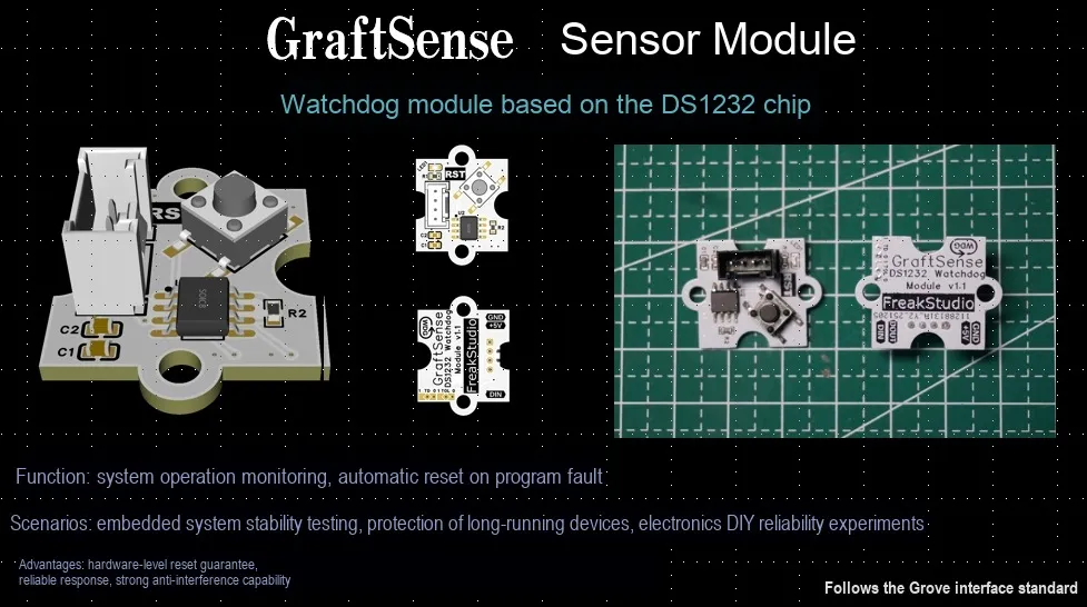
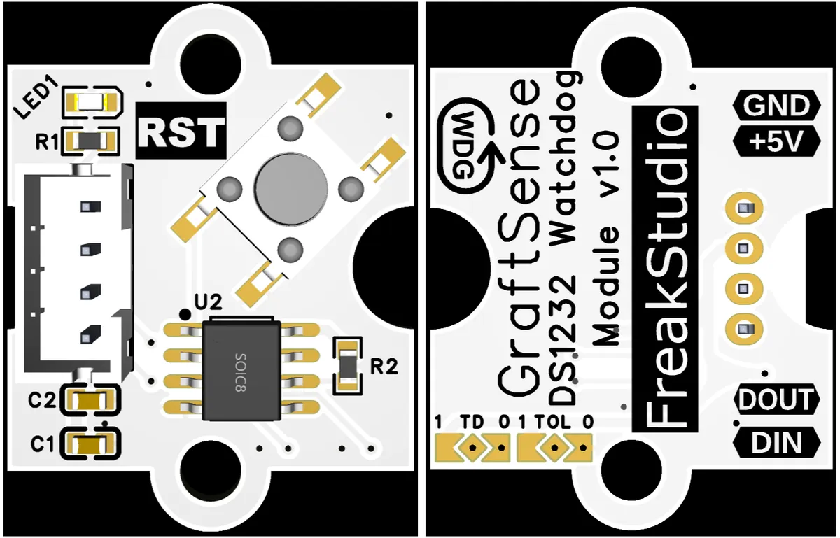
I. Module Introduction
Watchdog Module Based on DS1232 Chip with DS1232 chip as the core, integrates power supply monitoring and watchdog timing functions, communicates with the main controller via two digital interfaces DIN / DOUT, the onboard reset button can manually trigger system reset, supports reset control and status indication, provides reliable fault detection and reset guarantee for embedded systems, and is suitable for high-reliability electronic device scenarios.
II. Introduction to Major Chips
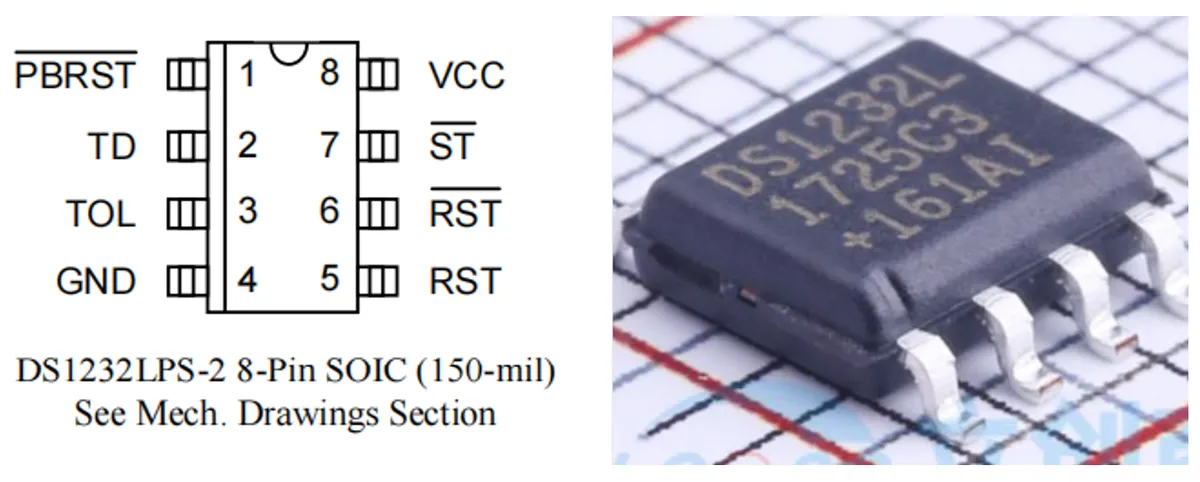
DS1232 is Maxim a microprocessor monitoring chip (Microprocessor Monitor) launched by the company.
Its main functions are as follows:
- Provides a watchdog timer function: If
the MCUfails to input a pulse signal to theST(strobe) pin within the specified time, the chip will trigger a reset. - Provides power supply voltage monitoring and reset functions: When the
VCCsupply voltage is lower than the reset threshold (approximately 4.37V or 4.62V, depending on the model), the chip automatically outputs a reset signal (RST). - Provides a manual reset interface: via the
PBRSTpin, users can connect an external button to manually trigger a reset.
Therefore, DS1232 is commonly used in scenarios that require high reliability such as microcontrollers and embedded systems.
2.1 Chip Overview
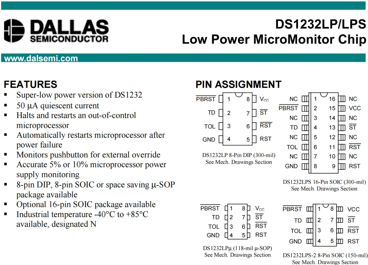
DS1232 is a power supply monitoring chip with a watchdog function, which is mainly used to ensure the stable operation of a single-chip microcomputer system when the power supply is abnormal or the program crashes, and realizes automatic reset by outputting a reset pulse. This chip adopts an 8-pin SMD package, has a built-in temperature compensation circuit, provides two options of power supply monitoring accuracy of 5% or 10%, and the threshold can be set via the TOL pin.
2.2 Pin Definition
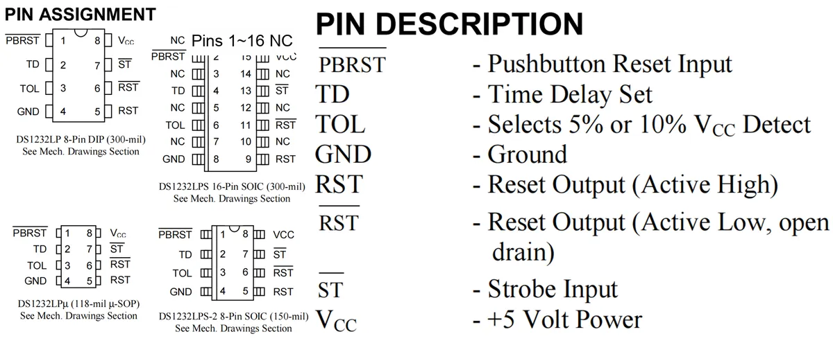
DS1232 The pin functions of the chip are shown in the following table:
Pin Name | Function Description |
VCC | Power Input (+ 5V) |
GND | Power Ground |
RST inverse | Reset output (active low, connected to MCU RESET pin) |
RST | Reset Output (active high, optional) |
ST | Watchdog refresh signal input (high-to-low transition) |
PBRST | External manual reset input (active low, internal debounce) |
TOL | Power supply threshold selection (connect to GND = 4.75V, connect to VCC = 4.5V) TD Watchdog Timeout Selection (the connection method determines 150ms/600ms/1.2s) |
TD | Watchdog timeout selection (150ms/600ms/1.2s determined by wiring) |
NC | NC (No function, for SOIC package) |
2.3 Functional Block Diagram
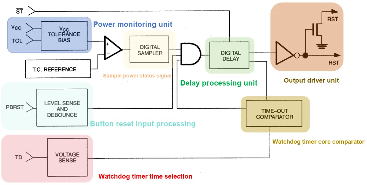
DS1232 The internal structure of the chip is shown in the figure, which mainly consists of the following parts:
- Power Supply Monitoring Unit (VCC Comparator + Reference + TOL): Detects whether the power supply voltage is normal.
- Principle: The power supply voltage VCC is compared with the internal temperature-compensated reference voltage, and the threshold is determined by the
TOLpin:TOL= GND: Threshold: 4.75VTOL= VCC: Threshold 4.5V
- Trigger Condition: When
VCCdrops below the threshold, the output signal is fed into the subsequent logic to force a system reset.
- Principle: The power supply voltage VCC is compared with the internal temperature-compensated reference voltage, and the threshold is determined by the
- Sampling Power Status Signal (Digital Sampler): It performs digital sampling on the output of the power comparator to filter out instantaneous interference, so as to prevent false resets caused by transient fluctuations or noise of the power supply. A reset will only be triggered when the power supply voltage remains below the threshold continuously.
- Button Reset Input Processing (Level Sense and Debounce, PBRST): Manually trigger a system reset.
- Principle:
PBRSTpin is connected to the button and is triggered at low level.- The internal circuit is equipped with debounce function to prevent multiple erroneous resets caused by the jitter of mechanical keys.
- After the key is released, the output reset signal will be maintained for 250ms to ensure reliable reset of the MCU.
- Principle:
- Watchdog Timer Time Selection (Voltage Sense, TD)
- Function: Sets the timeout period of the watchdog timer.
- Principle: Selection via the connection mode of the TD pin:
TD=GND:150msTD= Floating: 600msTD=VCC:1.2s
- The MCU must output a falling edge to the ST pin (dog feeding) within this timeframe; otherwise, a reset will be triggered.
- Watchdog Timer Core Comparator (Time-Out Comparator): It is used to determine whether the MCU feeds the watchdog within the specified time.
- Principle:
- If no falling edge is detected on the ST input within the set timeout period, the MCU is considered to be hung up, and a reset request will be output.
- If there is a valid transition of ST, the timer will be cleared and restarted.
- Principle:
- Delay Processing Unit (Digital Delay): Ensures the minimum duration of the reset signal.
- Principle: Regardless of whether the reset signal is triggered by power supply abnormality, key reset, or watchdog timeout, the Digital Delay will ensure that the reset output lasts for at least 250ms, preventing the MCU from abnormal startup caused by excessively short reset duration.
- Output Driver Unit (Output Driver, RST/RST̅): Outputs the reset control signal to the MCU.
- Principle:
- Provides two complementary outputs:
- RST (active low)
- RST̅(active high)
- It facilitates users to select the reset polarity suitable for the MCU.
- Provides two complementary outputs:
- Principle:
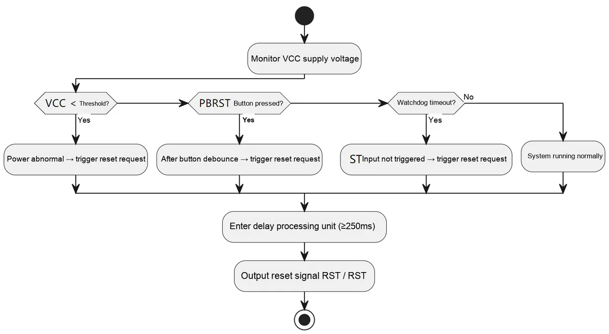
DS1232 monitors the VCC voltage via the power supply monitoring unit to detect if it drops below the set threshold. Once an abnormality is detected, it immediately outputs a reset signal, and maintains a reset delay of at least 250ms after power is restored to ensure system stability. Meanwhile, the chip supports a key reset input, which will also generate a reset pulse of no less than 250ms after internal debouncing. In addition, it has a built-in watchdog timer: if no trigger pulse from the processor is received within the set timeout period (150ms/600ms/1.2s), the system is considered to be hung up, and a reset signal is automatically issued.All reset requests are processed by the delay processing unit and then output uniformly via the output driver / / RST̅, to ensure that the microprocessor receives reliable reset control.
2.4 Performance Parameters
DS1232 's performance parameters can be analyzed from four dimensions: DC characteristics, AC characteristics, capacitance characteristics and key notes:
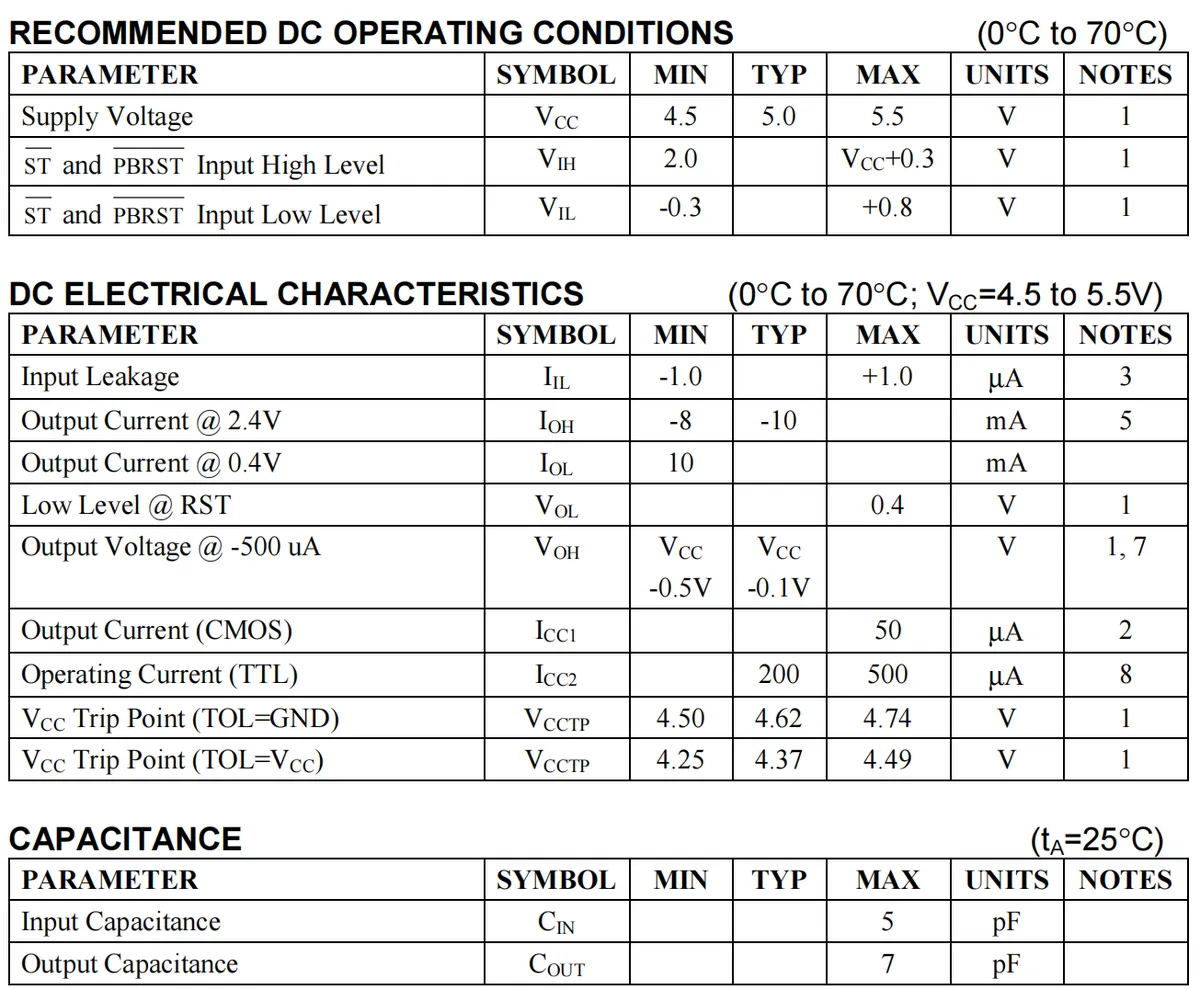
DC electrical characteristics (at 0℃~70℃, VCC = 4.5~5.5V) are as follows:
- Supply Voltage: 4.5~5.5V, typically 5.0V, which is the power supply range for normal operation of the chip.
- Input Level:
ST,PBRSTHigh level ≥ 2.0V, low level ≤ + 0.8V to ensure effective identification of input signals. - Input leakage current:±1.0μA, with ultra-low quiescent current to reduce system power consumption.
- Output Current:
RSTis an open-drain output, with a typical high-level sink current of 10mA and a low-level source current of 10mA, which meets the reset driving requirements of most main controllers. - Undervoltage threshold of power supply:
TOLwhen grounded, the threshold ranges from 4.50V to 4.74V;TOLwhen connected to supply voltage, the threshold ranges from 4.25V to 4.49V, realizing power supply abnormality monitoring.
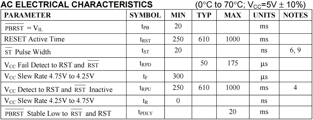
AC Electrical Characteristics (0℃~70℃, VCC = 5V±10%) are as follows:
- Manual reset pulse width:≥20ms, to ensure the manual reset signal is reliably recognized.
- Reset valid time: 250~1000ms (typically 610ms), which provides sufficient reset time for the main controller.
- Watchdog feeding pulse width:≥20ns; the main controller must complete the watchdog feeding operation within this duration, otherwise a reset will be triggered.
- Power Failure to Reset Response Time: Typical 50μs (max. 175μs), which triggers a reset rapidly in case of power supply abnormality.
- Power recovery to reset release time: 250~1000ms (typically 610ms), which reserves startup time for the system after power is restored.
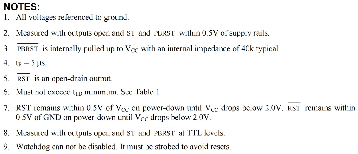
The key notes are as follows:
- The reset pin is an open-drain output (requires an external pull-up resistor),
PBRSThas an internal pull-up (typically 40kΩ), and you only need to pull this pin low for manual reset. - The watchdog cannot be disabled, and it must be regularly fed (triggered by
STpulses), otherwise the system will be forcibly reset. - When the power supply is powered down,
RSTwill remain at a level close to ground orVCCuntilVCCdrops below 2.0V, ensuring stable system status during the power-down process.
2.5 Reference Circuit
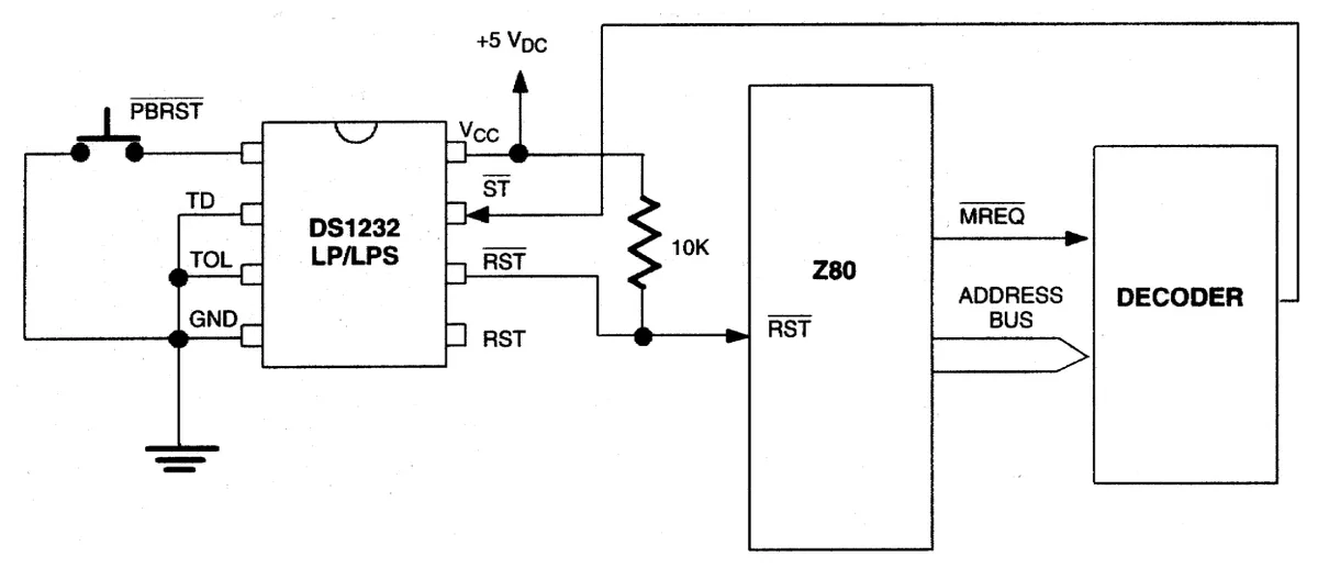
2.6 Chip Configuration
Note that the DS1232 is designed for 5V operation. If the IO level standard of the MCU in use is 3.3V, ensure proper level compatibility or select a 3.3V monitoring chip to avoid damaging the MCU.
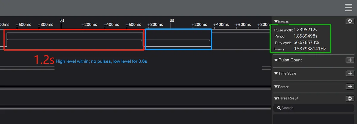
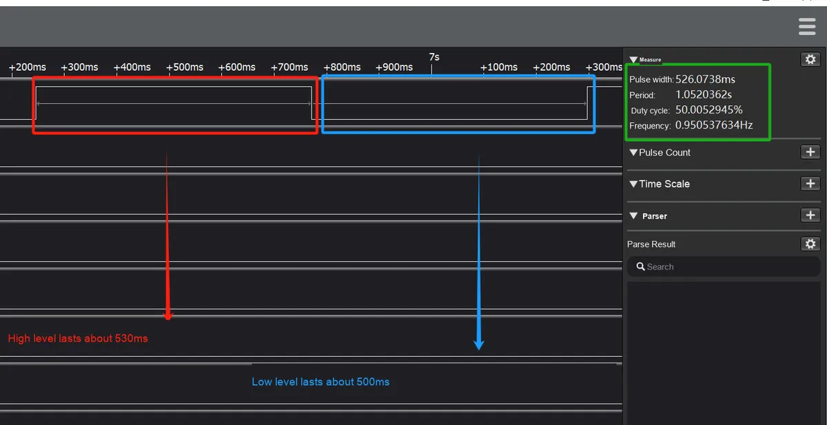
Below are the results of our module test. After powering on the module, we connected channel 0 of the logic analyzer to the RST interface of the watchdog module:
When TD is connected to VCC, the pulse interval shall not be greater than 1.2 seconds, and it is recommended to input a square wave with a frequency of 2Hz:
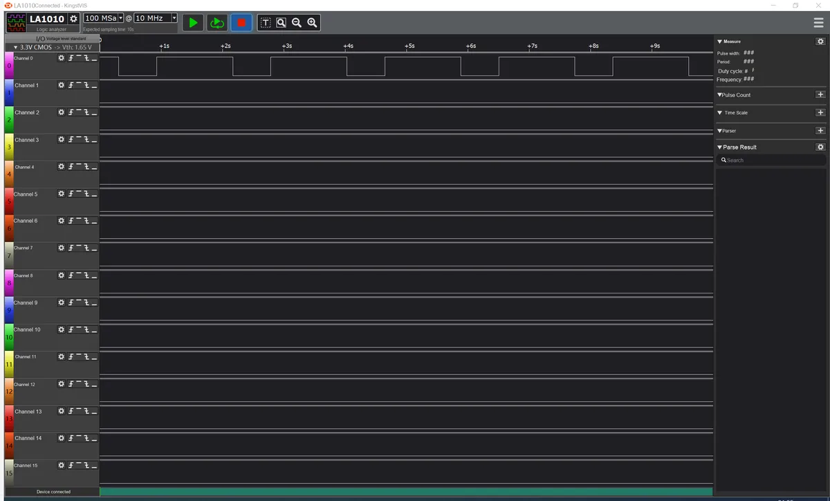
TD When floating, the pulse interval shall not exceed 600 ms, and a square wave with an input frequency of 10 Hz is recommended:
TD is connected to GND, the pulse interval shall not exceed 0.15 seconds, and a square wave with an input frequency of 30Hz is recommended:
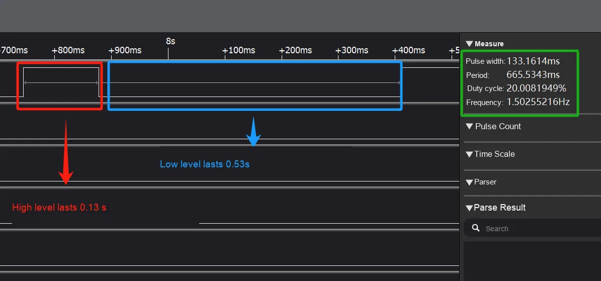
Here, we can see that in practical applications, the watchdog feeding frequency needs to be faster than what is specified in the chip datasheet, because DS1232 factors such as internal timing accuracy error, sampling delay, and pulse width requirements mean that strictly feeding the watchdog at the theoretical limit value will easily lead to failures. Therefore, in engineering practice, it is always recommended to set the watchdog feeding period to 1/2 of the timeout period or even shorter.
In the provided datasheet, we can also see that the timing accuracy is approximately −58.33% / + 66.67%(relative to the typical value):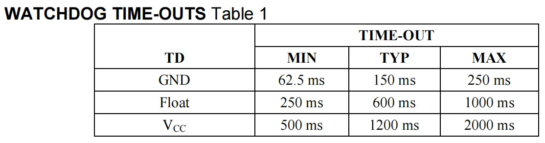
GNDGear: Typical value: 150 ms, minimum value: 62.5 ms (87.5 ms less than the typical value, approximately -58.33%), maximum value: 250 ms (100 ms greater than the typical value, approximately + 66.67%).FloatGear: Typical 600 ms, minimum 250 ms (difference 350 ms, approx. −58.33%), maximum 1000 ms (difference 400 ms, approx. + 66.67%).VCCGear: Typical value is 1200 ms, minimum value is 500 ms (a difference of 700 ms, approximately −58.33%), maximum value is 2000 ms (a difference of 800 ms, approximately + 66.67%).
2.7 Communication Interfaces and Related Protocols
None.
2.8 PCB Routing Precautions
None.
III. Instructions for Circuit Engineering and Module Usage
3.1 Circuit Source Engineering
To obtain the source project of the circuit, please follow the official account [Freak Embedded]
3.2 Module Usage Instructions
The schematic diagram of this module is shown below:
SCH_Watchdog Module Based on DS1232 Chip_v1.0_2025-10-24.pdf 1.8 MB
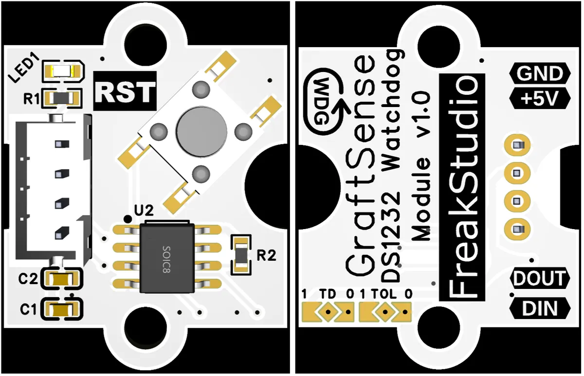
This module provides a pair of digital input/output interfaces DIN (RESET) and DOUT (WDI): Note that IN and OUT are defined relative to the main controller;DIN (RESET) functions as "main controller output, module input", which is used for the main controller to send reset control commands to the module or receive reset signals output by the module;DOUT (WDI) functions as "module output, main controller input", through which the module outputs a watchdog feeding detection signal to the main controller, and the main controller needs to periodically trigger WDI to prevent the module from triggering a system reset.
This module is equipped with a manual reset button, which allows manual triggering of system reset in emergency scenarios; it is configured with TD and TOL three short-circuit points, and users can flexibly configure by short-circuiting different points:
TDcan be selectively connected toGND(watchdog pulse interval ≤ 150ms),VCC(interval ≤ 1.2s) or left floating (interval ≤ 600ms);TOLcan be selectively connected toGND(outputs a reset pulse when the supply voltage drops to 4.75V) orVCC(outputs a reset pulse when the supply voltage drops to 4.5V).
3.3 Application Experiment
Here, we use the GraftPort-RP2040 development board for testing, and connect the watchdog module based on the DS1232 chip to communicate with the main controller via the DIO interface.
Here, we first need to solder the short-circuit points of the GraftSense-DS1232 watchdog module on the back side for TD and TOL to VCC respectively:
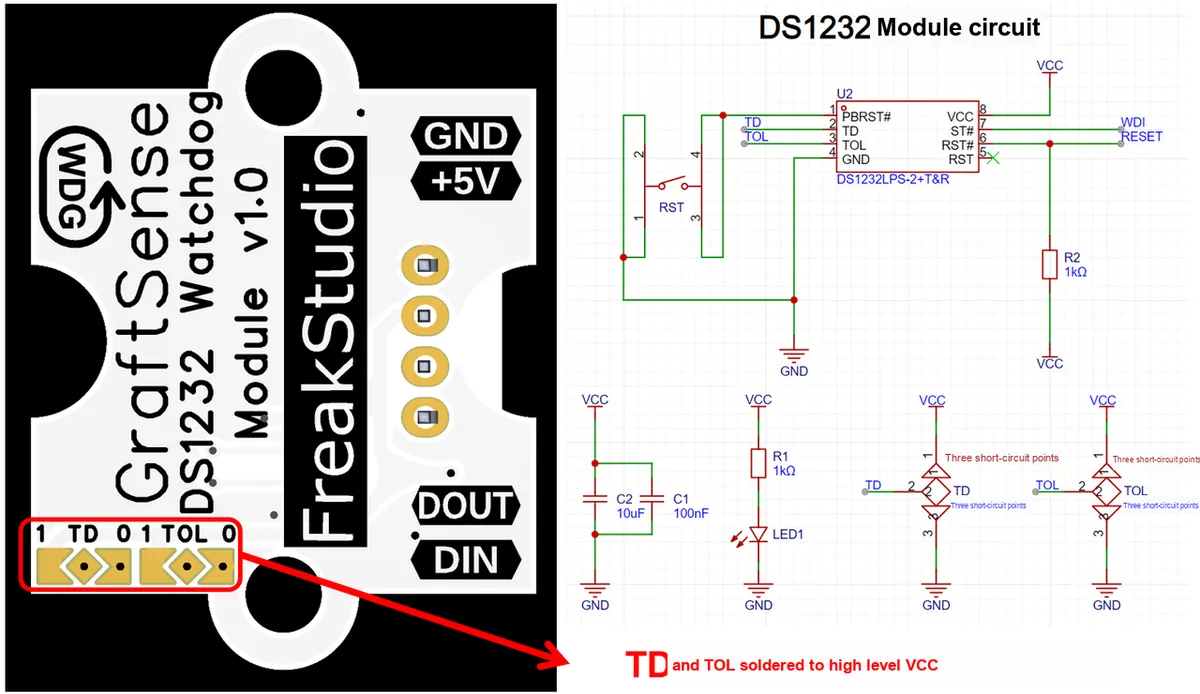
Then use the HY2.0-4P connection cable to connect the module to the GraftPort-RP2040 development board's DIO0 interface:
The module connections are shown in the following table:
Development Board Pins | Module Pins | Description |
Pin 6 |
| Watchdog Input: The MCU periodically toggles this pin to feed the watchdog. |
Pin 7 |
| Watchdog reset output (ResetOutput), the MCU can detect the reset signal via interrupt |
Here, we need to search for the relevant driver packages on uPyPI: https://upypi.net/zh/
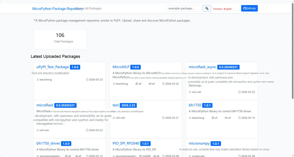
Enter ds1232_driver to search, and the following will be displayed:

Click to copy the local installation command:
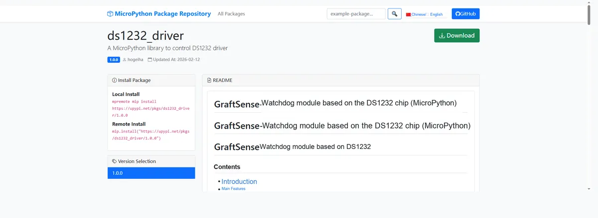
Here, we can use the mip tool to import module driver library code. Below are the usage commands for the mpremote tool:
mpremote mip install github:FreakStudioCN/GraftSense-Drivers-MicroPython/misc/ds1232_driverImport the DS1232 watchdog driver - MicroPython driver code, then copy the following main.py code into our project:
# Python env   : MicroPython v1.23.0
# -*- coding: utf-8 -*-
# @Time    : 2025/8/25 6:46 PM
# @Author  : Li Qingshui
# @File    : main.py
# @Description : External DS1232 watchdog module test program

# ======================================== Import Modules =========================================

# Import hardware-related modules
from machine import Pin, Timer
# Import time-related modules
import time

# Import the DS1232 watchdog module
from ds1232 import DS1232

# ======================================== Global Variables ============================================

# GPIO connected to the DS1232 WDI pin
WDI_PIN = 7
# GPIO connected to the DS1232 RST pin
RST_PIN = 6
# Feed interval, in ms
FEED_INTERVAL = 300
# Delay before stopping feeding, in ms
STOP_FEED_DELAY = 10000

# Define global variables
wdg = None
stop_feed_timer = None
# Global flag: detects whether RST was triggered
system_reset_flag = False

# ======================================== Functions ============================================

def rst_callback(pin: Pin) -> None:
    """
    DS1232 RST pin trigger callback function.

    Args:
        pin (Pin): The GPIO pin that triggered this callback.

    Returns:
        None
    """
    # Declare global variables
    global system_reset_flag

    # Set the flag; the main loop breaks out after detecting it
    system_reset_flag = True
    print("DS1232 RST pin triggered.")

def stop_feed_callback(t: Timer) -> None:
    """
    Timer callback: stop automatic feeding, simulating a feed failure to trigger a reset.

    Args:
        t (Timer): Timer object

    Returns:
        None
    """
    # Declare global variables
    global wdg, stop_feed_timer

    print("Stop feeding watchdog.")
    # Stop feeding
    wdg.stop()
    # Stop this timer so it runs only once
    stop_feed_timer.deinit()

# ======================================== Custom Classes ============================================

# ======================================== Initialization ==========================================

# Power-on delay of 3 s
time.sleep(3)
# Print debug information
print("FreakStudio:: DS1232 Watchdog Test Program.")

# Initialize the DS1232 watchdog
wdg = DS1232(wdi_pin=WDI_PIN, feed_interval=FEED_INTERVAL)
# Feed manually immediately
wdg.kick()

# Configure the RST pin as input with pull-up, triggering the callback
rst_pin = Pin(RST_PIN, Pin.IN, Pin.PULL_UP)
rst_pin.irq(trigger=Pin.IRQ_FALLING, handler=rst_callback)

# Define a timer to delay stopping feeding
stop_feed_timer = Timer()
stop_feed_timer.init(period=STOP_FEED_DELAY, mode=Timer.ONE_SHOT, callback=stop_feed_callback)

# ========================================  Main Program  ===========================================

# Start feeding
print("Start feeding watchdog.")

try:
    # Infinite loop
    while True:
        # Print a log with timestamp
        current_time = time.ticks_ms()
        print(f"System running... Time: {current_time} ms")

        # Check the RST trigger flag
        if system_reset_flag:
            print("System starting reset...")
            # Break out of the while loop
            break

        time.sleep(1)
except KeyboardInterrupt:
    print("Program interrupted.")
finally:
    # Stop feeding
    wdg.stop()
    # Stop the timer
    stop_feed_timer.deinit()
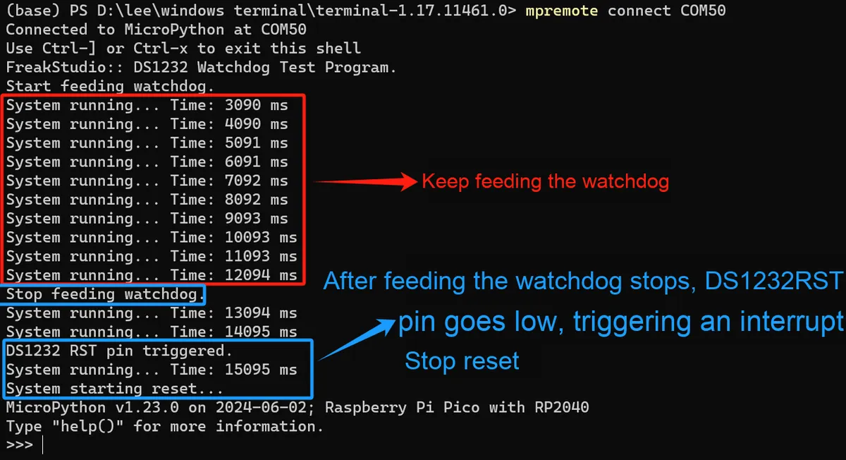
Here, first of all, the MCU will delay for 3 seconds after power-on to complete stable startup, then print debug information, and create a DS1232 object to initialize the WDI pin and the Timer to implement automatic periodic watchdog feeding; meanwhile, the kick () function is called immediately to manually toggle the WDI once to ensure the watchdog starts timing; next, configure the RST pin as input pull-up and bind an interrupt callback for detecting the DS1232 timeout reset signal; then start a one-shot timer to delay the stop of automatic watchdog feeding, so as to simulate watchdog feeding failure to trigger a reset. The program then enters the main loop:
- Prints the system running time (in milliseconds) every second.
- Check the
system_reset_flagflag; if theRSTpin is triggered, print the reset information and break out of the loop. - Catch
KeyboardInterruptto allow users to manually interrupt the program.
After the loop ends, stop the finally block from automatically feeding the DS1232 watchdog and release the timer resources to ensure the status safety of the MCU and Timer, thus completing the entire watchdog test process.
Burn the code, open a terminal, and use the mpremote tool to connect to the main controller; the output is as follows:
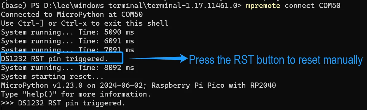
After a restart, before we stop feeding the watchdog, while the MCU is normally sending pulses to the watchdog, press the RST button on the watchdog module, and you will see that a normal reset can still be triggered. This design is intended to provide a reliable external hard reset mechanism: when the software malfunctions or you need to manually restart the entire board, manual reset should have the highest priority.
IV. Drivers
ds1232_driver.zip 10 KB
5. BOM & Recommended Alternative Parts
None.
VI. Revision History
Document Version | Date of Revision | Modifier | Modified Content |
v1.0 | 2025-10-24 | Li Zisheng | Initialize the document The BOM sheet has not been finally checked, the driver has not been re-verified, and the 3.3 application experiment Not yet specified. |
v1.1 | 2025-12-29 | Li Zisheng | Added application experiments and production files |
v1.2 | 2025-12-31 | Xin Ruili | Create an open version of the document based on the internal document version v1.1. |
v1.3 | 2026-03-29 | Xin Ruili | Modified the application experiment section |
VII. Relevant Materials
7.1 Chip Datasheet
DS1232 Watchdog Chip.pdf 99 KB
7.2 Unique Icons for PCB Silkscreen