Contents
- I. Module Introduction
- II. Introduction to Main Chips
- 2.1 Chip Overview
- 2.2 Pin Definition
- 2.3 Functional Block Diagram
- 2.4 Performance Parameters
- 2.5 Reference Circuit
- 2.6 Chip Configuration
- 2.7 Communication Interfaces and Related Protocols
- 2.8 PCB Routing Precautions
- III. Circuit Engineering
- 3.1 Circuit Source Engineering
- 3.2 Module Usage Instructions
- 3.3 Application Experiment
- IV. Drivers
- 5. BOM & Recommended Alternative Parts
- VI. Revision History
- VII. Relevant Materials
- 7.1 Chip Datasheet
- 7.2 Unique Icons for PCB Silk Screen
I. Module Introduction
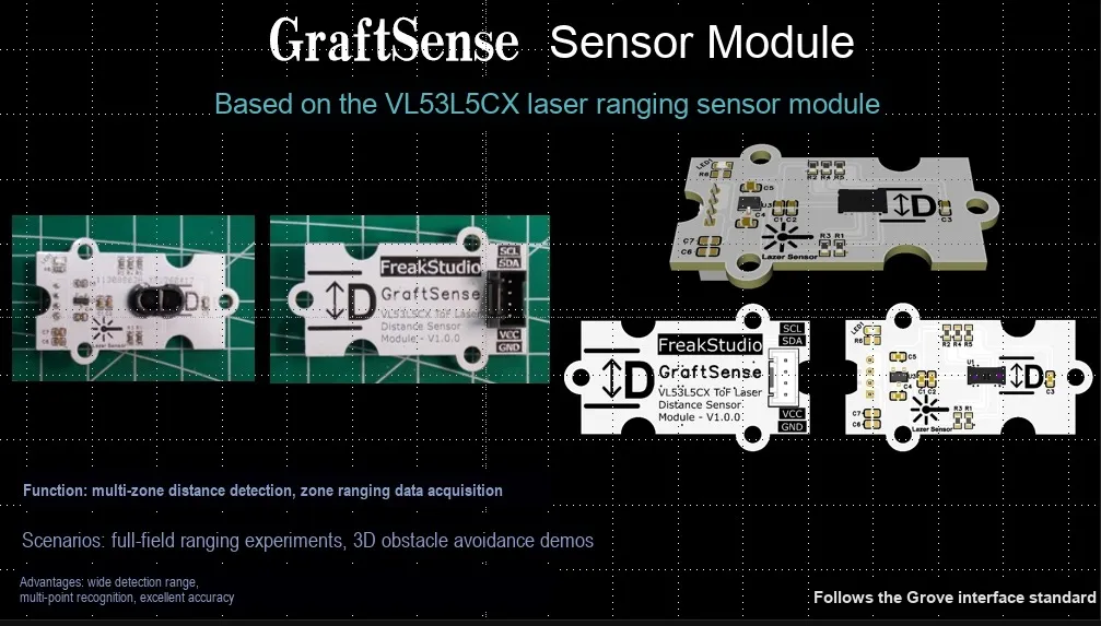
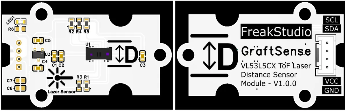
VL53L5CX-based laser ranging sensor module that adopts the STMicroelectronics VL53L5CX multi-zone ToF laser ranging chip solution, supports 4×4 or 8×8 multi-zone ranging, and can simultaneously detect the positions and contours of multiple targets; the module is equipped with LDO voltage regulator circuit, power filtering and indicator circuit, powered by 2.8~3.3V, with a ranging range of 0~400cm, outputs millimeter-level precision data, has strong anti-ambient light capability, can distinguish near and far objects, works through a glass cover, and is suitable for scenarios such as robot obstacle avoidance, smart home, and tablet devices.
II. Introduction to Main Chips
VL53L5CX is a multi-zone ToF sensor from STMicroelectronics that adopts FlightSense technology, can output 8×8 matrix ranging data, supports multi-target Object Detection, has a maximum frame rate of 15Hz, achieves a ranging distance up to 4 meters, features a built-in programmable field of view function, and integrates a 940nm infrared laser emitter and a SPAD receiving array.
2.1 Chip Overview
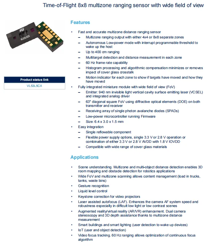
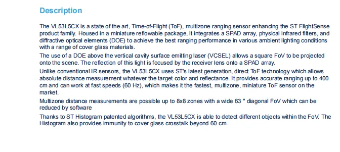
VL53L5CX is an 8×8 multi-zone FlightSense technology-based ToF sensor from STMicroelectronics, which adopts a 940nm laser and SPAD array, supports a maximum ranging distance of 4 meters and a frame rate of 60Hz, can realize multi-target Object Detection and area motion judgment, features a 63° field of view, has a built-in histogram algorithm to suppress crosstalk, and is widely used in 3D scene perception, gesture recognition, robot obstacle avoidance and other scenarios.
2.2 Pin Definition
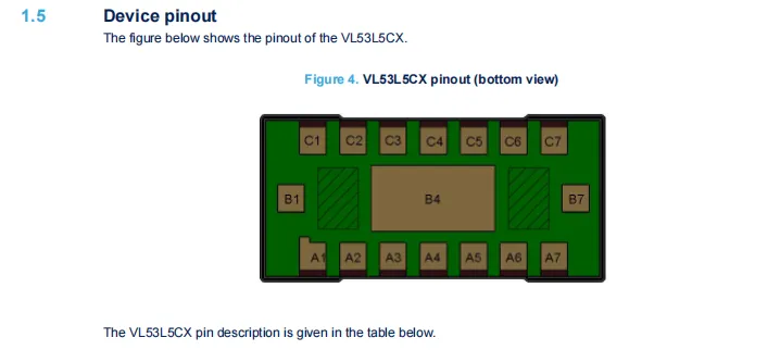
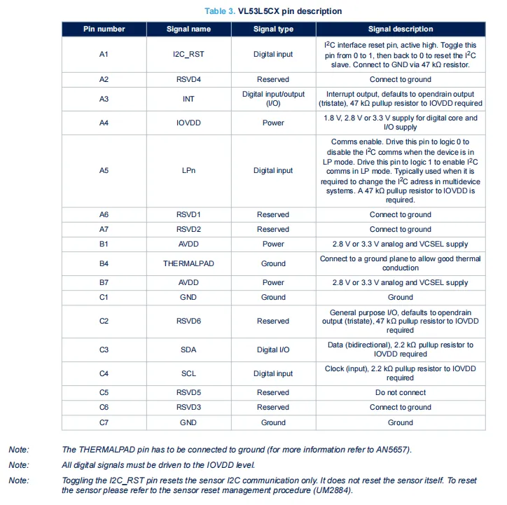
VL53L5CX features a 16-pin package with bottom view. AVDD is the supply pin for the analog circuitry and VCSEL, while IOVDD serves as the supply pin for the digital core. SDA / SCL form the I²C interface, INT is the open-drain interrupt output, I2C_RST is the I²C communication reset pin, and LPn is the communication enable pin. The THERMALPAD must be connected to ground for heat dissipation assistance, and multiple RSVD reserved pins shall be either grounded or left floating as required.
2.3 Functional Block Diagram
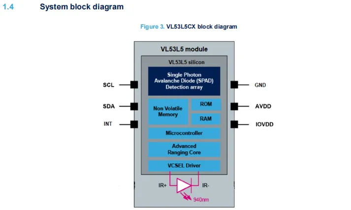
VL53L5CX operates based on the direct Time-of-Flight (ToF) principle: the VCSEL driver circuit drives the emission of 940nm infrared laser, the reflected light from the target is received by the Single-Photon Avalanche Diode (SPAD) array, the ranging core and microcontroller calculate the round-trip time of light to convert it into 8×8 multi-zone distance data, which is finally output via the I²C interface (SDA / SCL), the INT pin can output interrupt signals, and AVDD and IOVDD supply power for the analog / VCSEL and digital cores respectively.
2.4 Performance Parameters
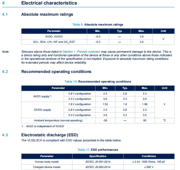
VL53L5CX the absolute maximum voltage of its power supply and signal pins ranges from -0.5V to 3.6V;AVDD supports 2.8V/3.3V configuration, IOVDD is selectable among 1.8V/2.8V/3.3V modes, with an operating temperature range of -30℃ to 85℃; meanwhile, the device complies with the ESD protection standards of ±2kV (Human Body Model) and ±500V (Charged Device Model).
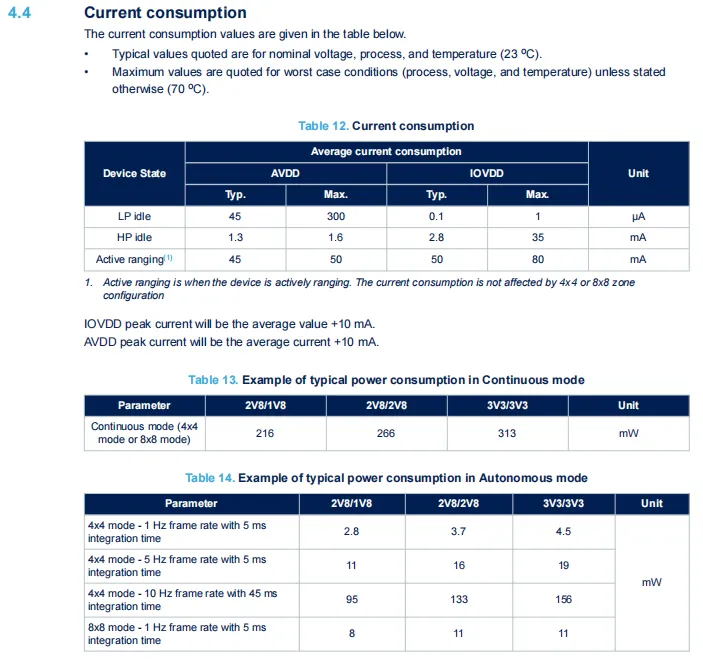
VL53L5CX features a typical low-power (LP) standby current of only 45μA (at AVDD); in ranging mode, the average currents of AVDD and IOVDD are 45mA and 50mA respectively, with the peak current 10mA higher than the average value; the typical power consumption in continuous ranging mode ranges from 216 to 313mW, while in autonomous mode it varies with frame rate and integration time, reaching a minimum of 2.8mW.
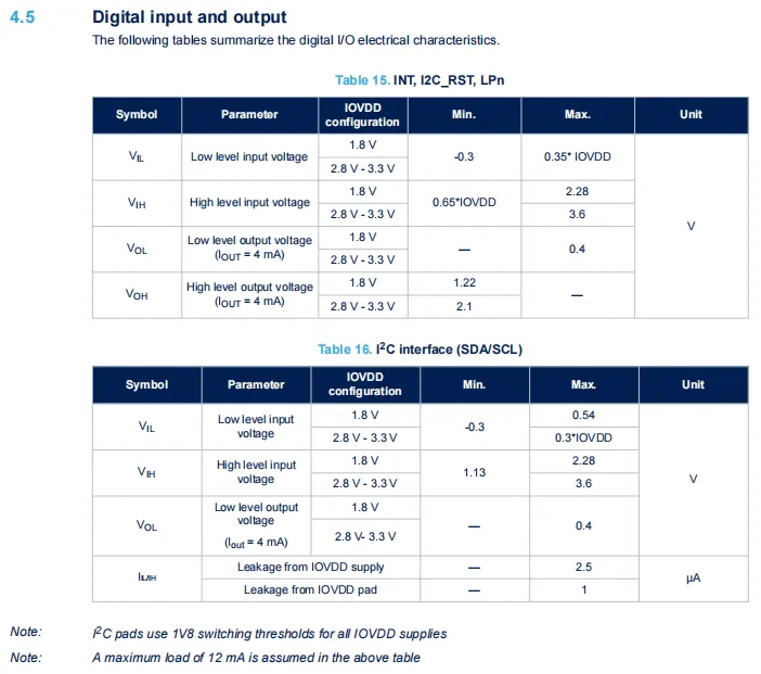
VL53L5CX digital I/O features are classified by IOVDD configuration: INT, I2C_RST, LPn pins and the I²C interface (SDA / SCL) have specified parameters for high/low level input voltage, output voltage and leakage current respectively. Among them, the switching threshold of the I²C interface is fixed to the 1.8V standard, with extremely low pin leakage current, and the overall electrical characteristics meet the level specifications for different power supply scenarios such as 1.8V and 2.8V~3.3V.
2.5 Reference Circuit
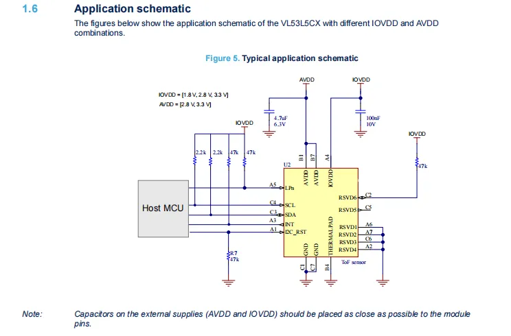
AVDD (2.8V/3.3V) and IOVDD (1.8V/2.8V/3.3V) power supply pins require 4.7μF and 100nF filter capacitors connected in parallel nearby respectively;SDA / SCL, INT, LPn, I2C_RST and other signal pins are connected to IOVDD via 2.2kΩ or 47kΩ pull-up resistors, reserved pins shall be grounded or connected to IOVDD as required, THERMALPAD must be grounded for auxiliary heat dissipation, and the entire circuit communicates with the I²C interface to the Host MCU to implement multi-region ranging function.
2.6 Chip Configuration
None.
2.7 Communication Interfaces and Related Protocols
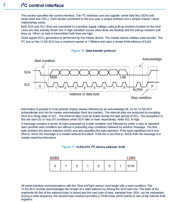
VL53L5CX I²C interface adopts the standard master-slave Communication Protocol. The SDA / SCL lines need to be connected to the pull-up resistors on the host, with a maximum rate of 1Mbps, and the default slave address is 0x52 (the least significant bit is 0/1 respectively during read and write operations, corresponding to addresses 0x52 / 0x53). The communication follows the start, stop and acknowledge mechanisms. When performing a write operation, a 16-bit register index needs to be sent after the address, and standard 8-bit data packet transmission is supported.
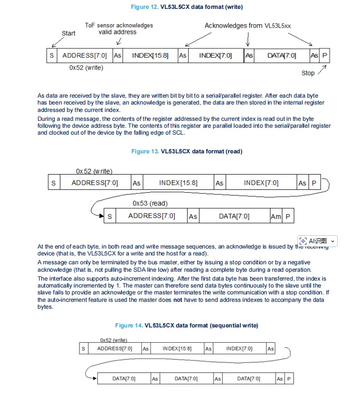
VL53L5CX write operations start at the 0x52 address, sending the 16-bit register index and data in sequence; for read operations, the index must first be sent by writing to the address, then reading starts at the 0x53 address; sequential write supports automatic address increment, eliminating the need to resend the index, with an acknowledge bit after each byte transmission.
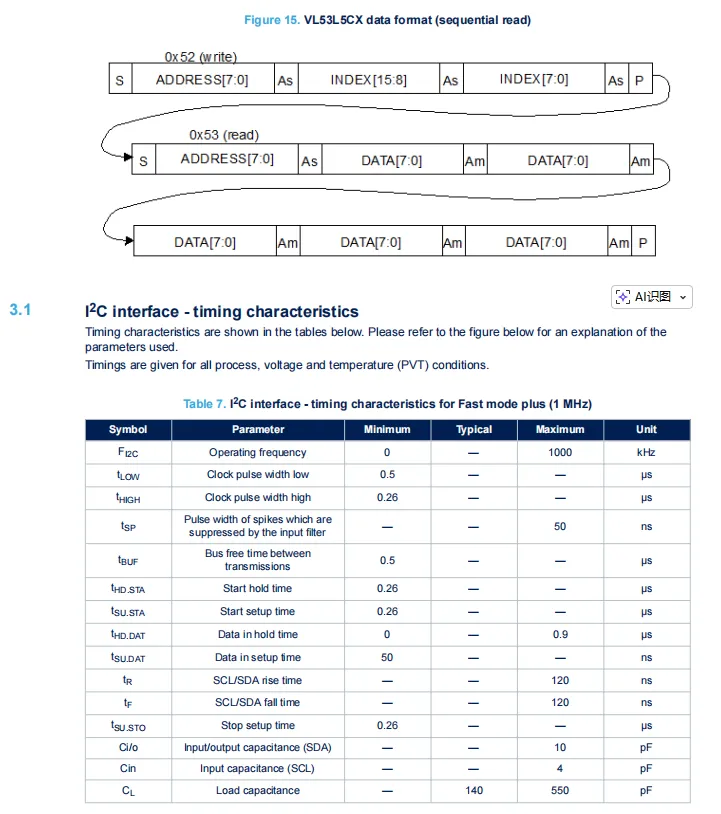
VL53L5CX 's I²C interface supports Fast Mode+ communication at a maximum rate of 1MHz. Its timing specifications define key parameters including the high and low pulse widths of the clock, setup/hold times, and rise/fall times. It also supports continuous read operations with automatic address increment, enabling batch reading of data from multiple registers.
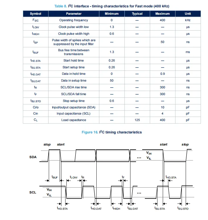
VL53L5CX I²C Fast Mode (400kHz) timing specifications define parameters including clock high/low level width, setup/hold time, rise/fall time, and bus idle time, and clearly specify the timing relationship of SDA / SCL signals during start, stop and data transmission in conjunction with the Sequence Diagram, ensuring stable and reliable I²C communication.
2.8 PCB Routing Precautions
None.
III. Circuit Engineering
3.1 Circuit Source Engineering
To obtain the circuit source project, please follow the official account [Freak Embedded]
3.2 Module Usage Instructions
The schematic diagram of this module is shown below:
SCH_Schematic1_VL53L5CX-based laser ranging sensor module_v1.0.0_2026-05-09.pdf 2.4 MB
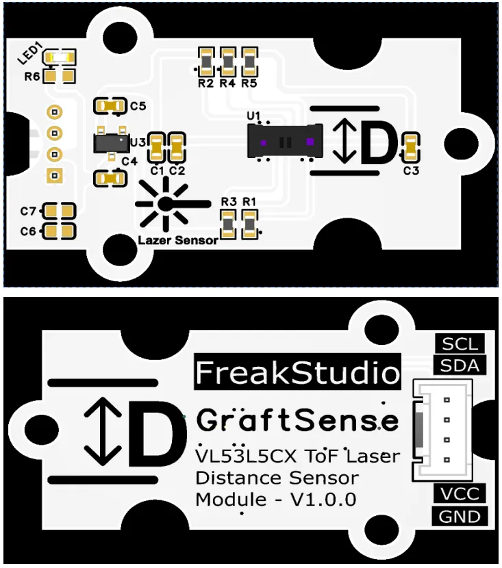
This module provides an I2C communication interface: it is compatible with the standard I2C protocol, supports a maximum communication rate of 1Mbps, has a default device address of 0x52 (the read/write mode automatically switches to 0x52 / 0x53), is compatible with the 3.3V level specification, can stably transmit 8×8 multi-region ranging data, supports read and write operations with continuous address increment, and cooperates with the main controller to achieve millimeter-level precision multi-target distance and contour detection, providing a reliable high-speed data interaction channel for applications such as robot obstacle avoidance, gesture recognition, and scene perception.
3.3 Application Experiment
Here, we use the GraftPort-RP2040 development board for testing, and the VL53L5CX-based laser ranging sensor module uses the I2C interface to communicate with the main controller.
Here, we first use the HY2.0-4P cable to connect the module to the GraftPort-RP2040 development board's I2C0 interface:
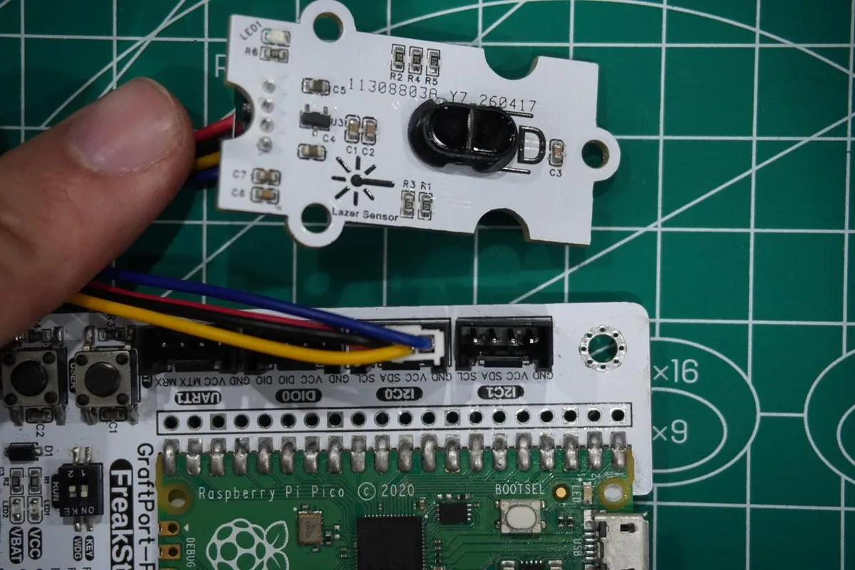
The module connections are shown in the following table:
development board pins | Module Pins | Description |
Pin 4 |
|
|
Pin 5 |
|
|
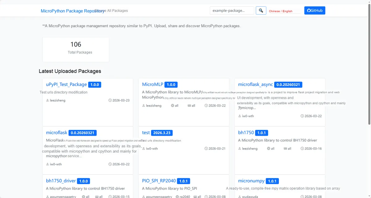
Here, we need to search for the relevant driver packages on uPyPI: https://upypi.net/zh/
Enter vl53l5cx_driver to search, and the following will be displayed:
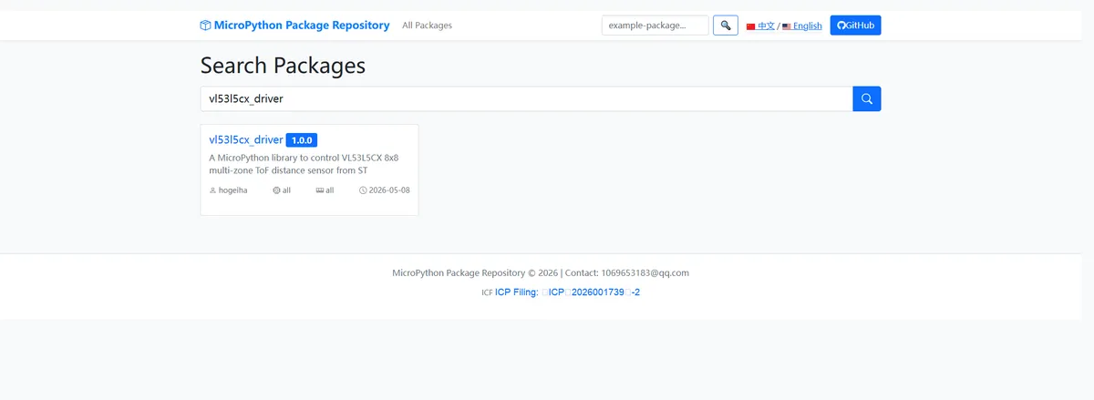
Click to copy the local installation command:
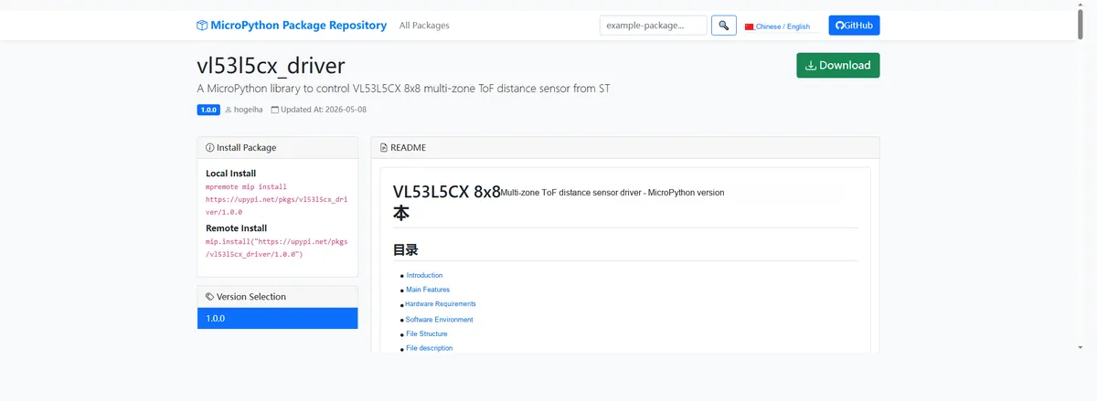
Import the module driver library code via the mip tool. Below are the usage commands for the mpremote tool:
mpremote mip install https://upypi.net/pkgs/vl53l5cx_driver/1.0.0Import the VL53L5CX-based laser ranging sensor module - MicroPython driver code, then copy the following main.py code into our project:
# Python env   : MicroPython v1.23.0
# -*- coding: utf-8 -*-
# @Time    : 2026/05/06 09:00
# @Author  : hogeiha
# @File    : main.py
# @Description : Code to test the VL53L5CX 8x8 multi-zone ToF distance sensor driver class
# @License : MIT

# ======================================== Import Modules =========================================

import time
from machine import I2C, Pin
from os import stat
from vl53l5cx.mp import VL53L5CXMP
from vl53l5cx import DATA_DISTANCE_MM, DATA_TARGET_STATUS
from vl53l5cx import RESOLUTION_4X4, STATUS_VALID, STATUS_VALID_LARGE_PULSE

# ======================================== Global Variables ============================================

VL53L5CX_ADDR = 0x29
I2C_SDA_PIN = 4
I2C_SCL_PIN = 5
LPN_PIN = 6
I2C_FREQ = 1_000_000
SENSOR_RESOLUTION = RESOLUTION_4X4
GRID_SIZE = 4
RANGING_FREQ = 2
FIRMWARE_FILE = "vl53l5cx/vl_fw_config.bin"

# ======================================== Functions ============================================

def print_distance_grid(distance, status, grid_size: int) -> None:
    """
    Print the distance grid, with invalid points shown as xxxx
    Args:
        distance: List of distance data
        status: List of target statuses
        grid_size (int): Grid side length
    Raises:
        ValueError: The parameter is empty or the grid is invalid
        TypeError: grid_size has an invalid type
    ==========================================
    Print distance grid; invalid points shown as xxxx.
    """
    if distance is None:
        raise ValueError("Distance cannot be None")
    if status is None:
        raise ValueError("Status cannot be None")
    if grid_size is None:
        raise ValueError("Grid size cannot be None")
    if not isinstance(grid_size, int):
        raise TypeError("Grid size must be integer")
    if grid_size <= 0:
        raise ValueError("Grid size must be greater than zero")

    for index, value in enumerate(distance):
        if status[index] in (STATUS_VALID, STATUS_VALID_LARGE_PULSE):
            print("{:4}".format(value), end=" ")
        else:
            print("xxxx", end=" ")
        if (index + 1) % grid_size == 0:
            print("")
    print("")

# ======================================== Custom Classes ============================================

# ======================================== Initialization ==========================================

time.sleep(3)
print("FreakStudio: Using VL53L5CX 8x8 multi-zone ToF distance sensor ...")

# Check whether the firmware resource file exists
try:
    stat(FIRMWARE_FILE)
except OSError:
    raise SystemExit("Missing firmware file: %s" % FIRMWARE_FILE)

# Initialize I2C bus
i2c_bus = I2C(0, scl=Pin(I2C_SCL_PIN), sda=Pin(I2C_SDA_PIN), freq=I2C_FREQ)

# Scan I2C bus devices
devices_list = i2c_bus.scan()
print("START I2C SCANNER")

if len(devices_list) == 0:
    raise RuntimeError("I2C scan found no devices")
print("I2C devices found: %d" % len(devices_list))

if VL53L5CX_ADDR not in devices_list:
    raise RuntimeError("VL53L5CX not found on I2C bus")
print("I2C address: %s" % hex(VL53L5CX_ADDR))

# Initialize the LPn reset control pin
lpn_pin = Pin(LPN_PIN, Pin.OUT, value=1)

# Create a sensor object
tof = VL53L5CXMP(i2c_bus, addr=VL53L5CX_ADDR, lpn=lpn_pin)

# Reset the sensor
tof.reset()

# Check whether the sensor is online
if not tof.is_alive():
    raise RuntimeError("VL53L5CX not detected")
print("Sensor initialization successful")

# Initialize the sensor firmware and configuration
tof.init()

# Set the ranging resolution and frequency
tof.resolution = SENSOR_RESOLUTION
tof.ranging_freq = RANGING_FREQ

# Start ranging, enabling distance and target status output
tof.start_ranging({DATA_DISTANCE_MM, DATA_TARGET_STATUS})
print("Start ranging")

# ========================================  Main Program  ===========================================

try:
    while True:
        # Check whether there is new ranging data
        if tof.check_data_ready():
            results = tof.get_ranging_data()
            print_distance_grid(results.distance_mm, results.target_status, GRID_SIZE)
        time.sleep_ms(50)

except KeyboardInterrupt:
    print("Program interrupted by user")
except OSError as e:
    print("Hardware communication error: %s" % str(e))
except Exception as e:
    print("Unknown error: %s" % str(e))
finally:
    print("Cleaning up resources...")
    tof.deinit()
    del tof
    print("Program exited")
Burn the code, open the terminal, and the output is as follows:
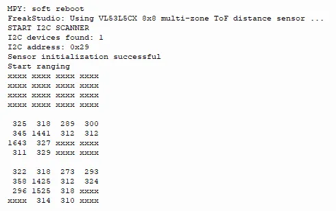
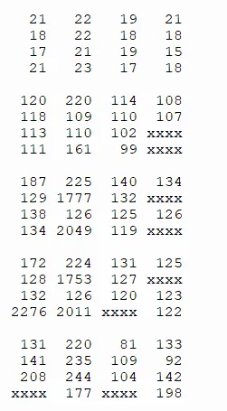
The VL53L5CX 8×8 multi-zone ToF sensor functions normally in terms of I2C communication and initialization; after ranging is started, it outputs 8×8 grid distance data, with values updated in real time as objects move closer or farther away, and some invalid areas display xxxx, indicating that the sensor's multi-zone ranging response is normal.
IV. Drivers
vl53l5cx_driver-1.0.0.zip 179 KB
5. BOM & Recommended Alternative Parts
None.
VI. Revision History
Document Version | Date of Revision | Modifier | Modify Content |
v1.0 | 2026-05-09 | Zero High-Luck | Initialize the document |
v1.1 | 2026-06-03 | Xin Ruili | Sorting completed. |
VII. Relevant Materials
7.1 Chip Datasheet
VL53L5CX.pdf 3.2 MB
7.2 Unique Icons for PCB Silk Screen