Contents
- I. Module Introduction
- II. Introduction to Main Chips
- 2.1 Chip Overview
- 2.2 Pin Definition
- 2.3 Functional Block Diagram
- 2.4 Performance Parameters
- 2.5 Reference Circuit
- 2.6 Chip Configuration
- 2.7 Communication Interfaces and Related Protocols
- 2.8 PCB Routing Precautions
- III. Circuit Engineering
- 3.1 Circuit Source Engineering
- 3.2 Module Usage Instructions
- 3.3 Application Experiment
- IV. Drivers
- 5. BOM & Recommended Alternative Parts
- VI. Revision History
- VII. Relevant Materials
- 7.1 Chip Datasheet
- 7.2 Unique Icons for PCB Silk Screen
I. Module Introduction
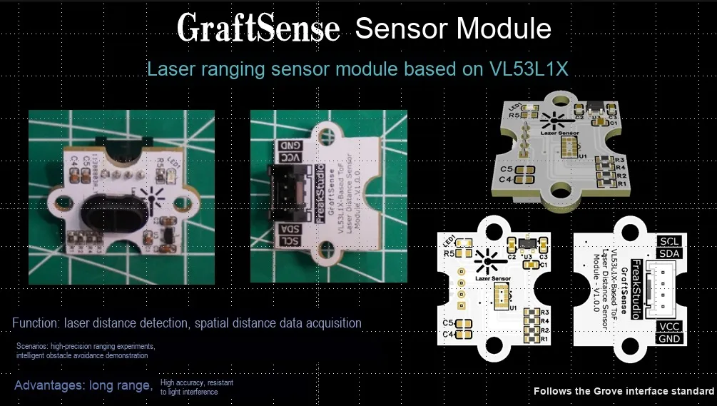
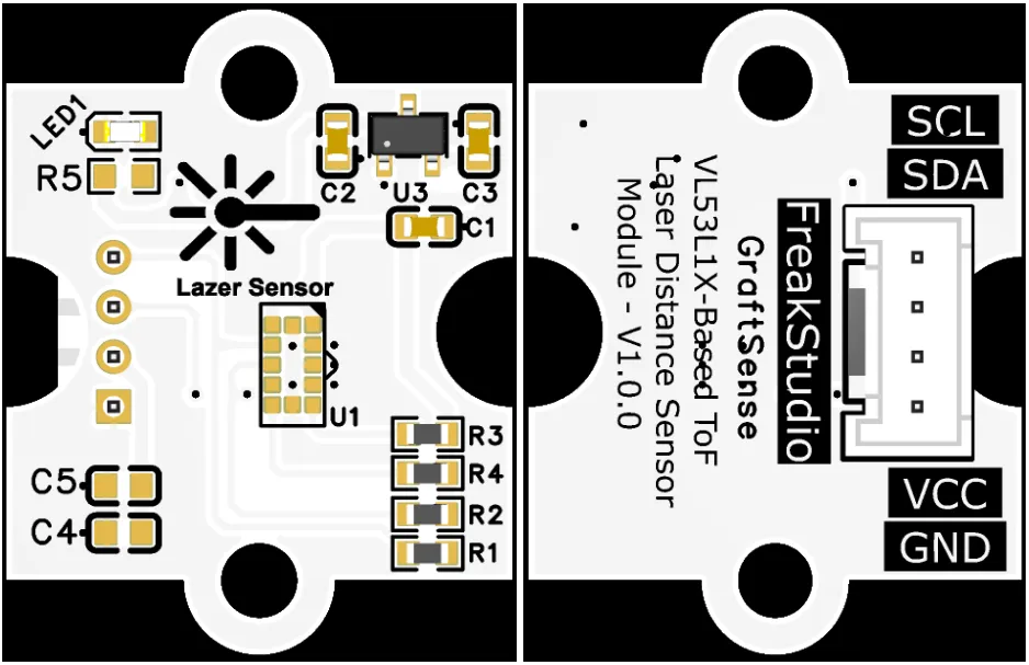
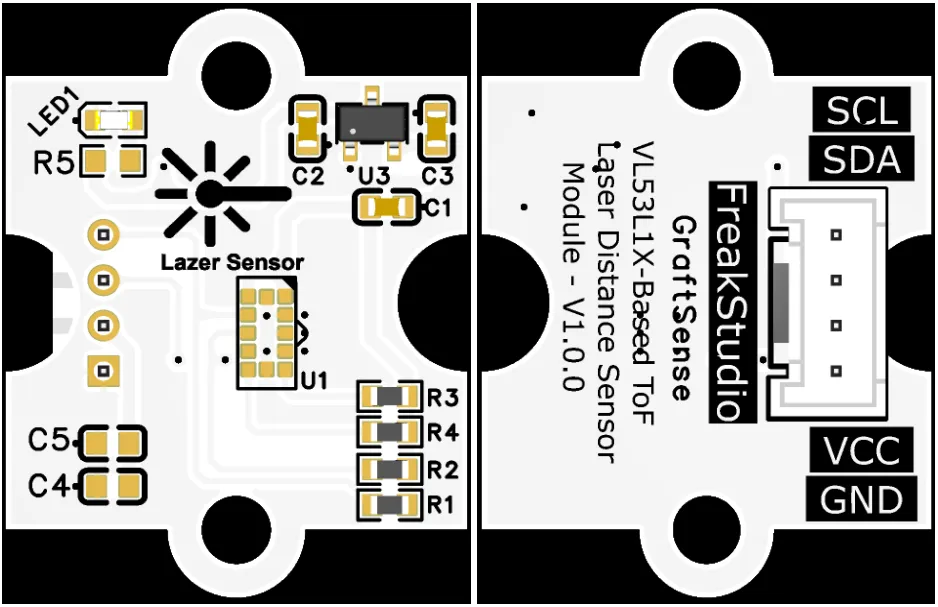
VL53L1X-based laser ranging sensor module that adopts the VL53L1X Time-of-Flight (ToF) ranging chip solution, which can realize non-contact distance detection with millimeter-level accuracy, supports distance measurement from 4 to 50 cm and directly outputs digital distance values; the module is equipped with LDO voltage regulator circuit, power filtering and indicator circuit, powered by 3.3V, communicates with the main controller via the I2C interface, has an operating voltage of 2.7~5.5V, features better stability than traditional infrared sensors, and is suitable for scenarios such as robot obstacle avoidance, distance detection, and gesture recognition.
II. Introduction to Main Chips
VL53L1X is a miniature FlightSense technology-based ToF laser ranging sensor from STMicroelectronics, integrating a 940nm laser, a SPAD array and an I²C interface. It features a ranging distance of up to 4 meters, a frame rate of 50Hz, programmable ROI, and dimensions of 4.9×2.5×1.56mm.
2.1 Chip Overview
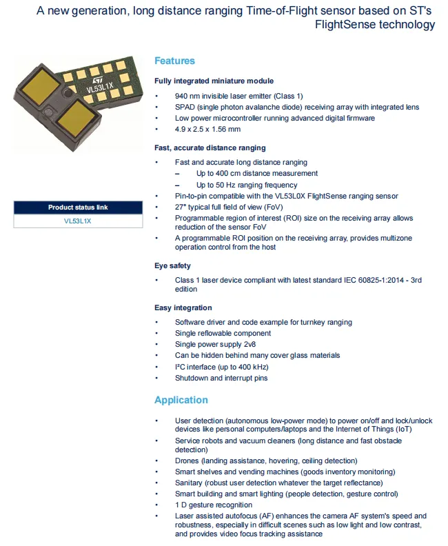
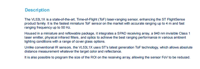
VL53L1X is a new-generation FlightSense technology-based ToF laser ranging sensor launched by STMicroelectronics, which integrates a 940nm Class 1 laser emitter, a SPAD receiving array and a microcontroller. It features a maximum ranging distance of 4 meters, a frame rate up to 50Hz, supports programmable FOV adjustment and multi-region operation, with the I2C interface supporting a maximum speed of 400kHz. It is compatible with a variety of embedded systems and is widely used in device sensing, robot obstacle avoidance, drones, smart shelves and other scenarios.
2.2 Pin Definition
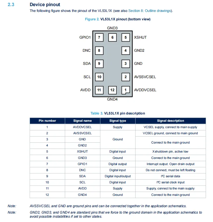
VL53L1X features 12 pins, among which AVDD and AVDDVCSEL are power supply pins;AVSSVCSEL, GND, and GND2 /3/4 are ground pins;SDA / SCL serve as the I²C communication interface;GPIO1 functions as an open-drain interrupt output;XSHUT is an active-low shutdown control pin, and Pin 8 (DNC) must be left floating.
2.3 Functional Block Diagram
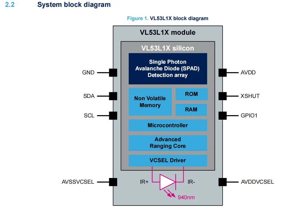
VL53L1X operates based on the time-of-flight (ToF) principle: the VCSEL driver circuit emits 940nm infrared laser, the reflected light from the target is received by a single-photon avalanche diode (SPAD) array, the built-in ranging core and microcontroller calculate the round-trip time of the light to convert it into distance data, and the result is finally output via the I²C interface (SDA / SCL). The XSHUT pin can control the module to enter sleep mode, GPIO1 can output interrupt signals, and the power supply and ground pins provide stable power for the chip and the laser emission section.
2.4 Performance Parameters
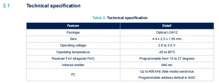
VL53L1X adopts the LGA12 package, measures 4.4×2.5×1.56mm in dimensions, operates at a voltage of 2.6–3.5V and a temperature range of -20 to 85°C, integrates a 940nm infrared emitter, features a receive field of view programmable between 15–27°, supports I²C communication up to 400kHz, and has a default address of 0x52.
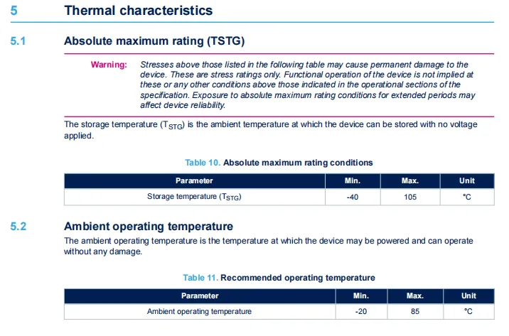
VL53L1X has a storage temperature range of -40 to 105°C and a recommended operating temperature range of -20 to 85°C. Exceeding the limit values may cause permanent damage, and long-term operation under extreme conditions will also affect the reliability of the device.
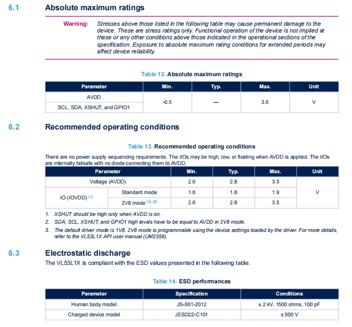
AVDD and I/O pins have an absolute maximum voltage range of -0.5V to 3.6V, and the recommended supply voltage for AVDD is 2.6–3.5V;IOVDD supports selectable modes including the standard mode (1.6–1.9V) and 2V8 mode (2.6–3.5V). Meanwhile, the device complies with ESD protection standards of ±2kV (Human Body Model) and ±500V (Charged Device Model).
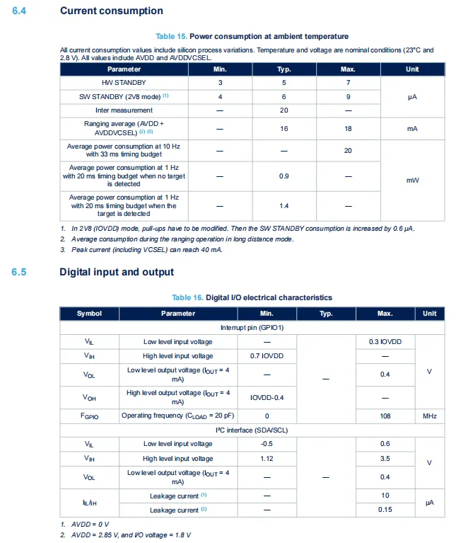
VL53L1X has a typical hardware standby current of 5μA, a typical average current of 16mA in ranging mode, and a peak current up to 40mA;GPIO1 and I²C interface parameters including high/low level and leakage current are all specified;I²C has a minimum high-level input voltage of 1.12V;GPIO1 supports a maximum output frequency up to 108MHz.
2.5 Reference Circuit
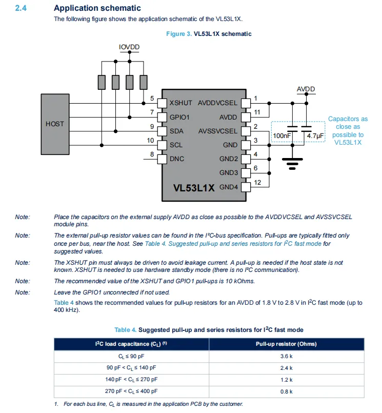
VL53L1X in its typical application circuit, AVDD and AVDDVCSEL power supply terminals require 100nF and 4.7μF capacitors connected in parallel nearby for filtering;SDA / SCL are connected to the host I²C bus, with corresponding pull-up resistors (0.8k~3.6kΩ) selected according to the load capacitance;XSHUT pin controls the module's sleep mode via a 10kΩ pull-up resistor;GPIO1 can be used as an interrupt output and left floating when unused, and all ground pins must be connected to the system ground.
2.6 Chip Configuration
None.
2.7 Communication Interfaces and Related Protocols
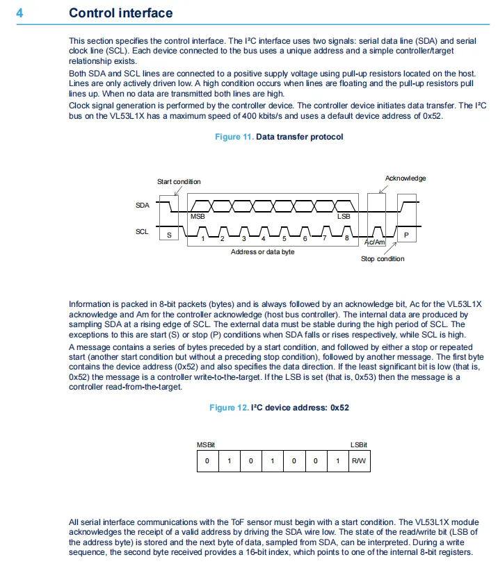
VL53L1X communicates via the I²C interface. The SDA / SCL lines require pull-up resistors on the host side, with a maximum rate of 400kHz. The default device address is 0x52 (the least significant bit is 0/1 for write/read operations respectively, corresponding to addresses 0x52 / 0x53). Its communication follows the standard I²C protocol: it starts with a start condition, ends with a stop condition, data transmission comes with acknowledge bits, and the byte following the address is used to specify the internal register address.
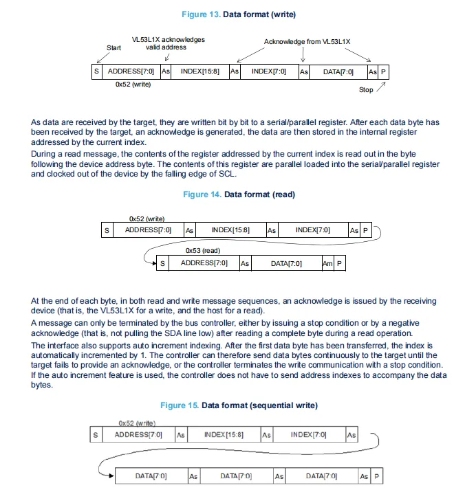
VL53L1X I²C read and write operations follow the standard protocol: a write operation starts at address 0x52, sends the 16-bit register index and data bytes in sequence, with an acknowledgment after each byte; for a read operation, the index must first be sent in write mode, then the read process is initiated at address 0x53 to read data; it also supports a continuous write mode with automatic address increment, which enables batch data transmission to improve communication efficiency.
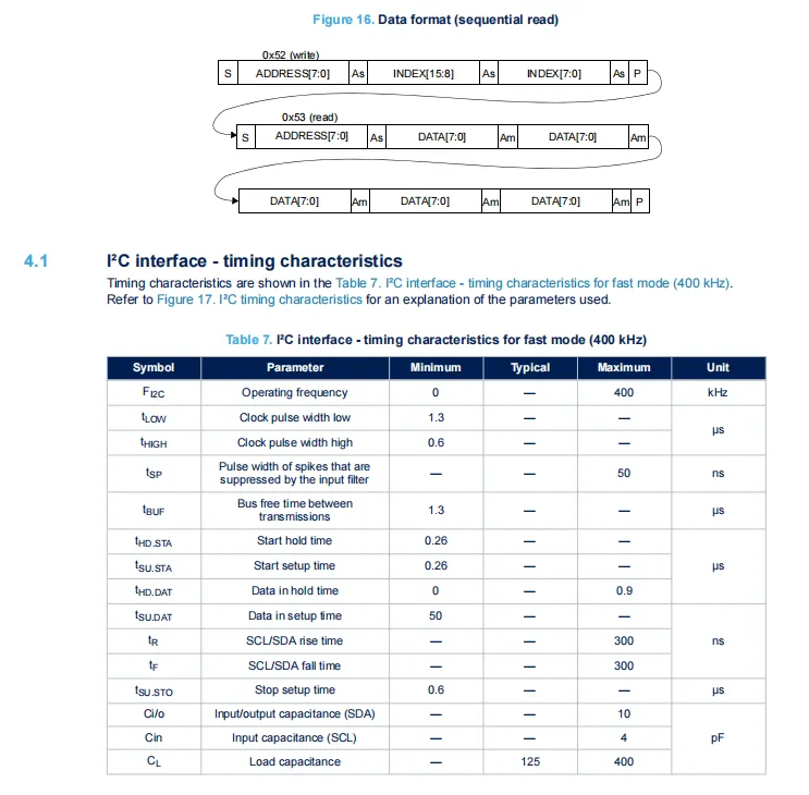
VL53L1X 's I²C interface supports the Fast Mode of up to 400kHz. Its timing characteristics specify parameters such as the high and low level widths of the clock, setup/hold time, rise/fall time, etc. It also supports continuous read operation with automatic address increment, enabling batch reading of data from multiple registers.
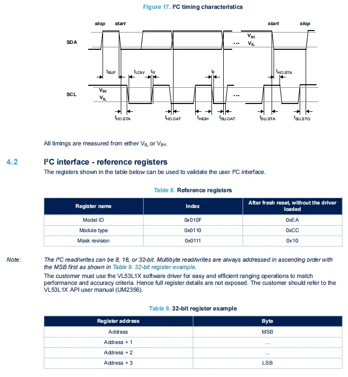
VL53L1X 's I²C Sequence Diagram defines key timing parameters such as the setup time, hold time, and high/low levels of SDA / SCL, and also provides reference registers including Model ID and Module type for interface verification. Multi-byte read and write operations are transmitted in ascending order of addresses with the high-order bit first, and the complete register details can be obtained from the official API driver manual.
2.8 PCB Routing Precautions
None.
III. Circuit Engineering
3.1 Circuit Source Engineering
To obtain the source code of the circuit, please follow the official account [Freak Embedded]
3.2 Module Usage Instructions
The schematic diagram of this module is shown below:
SCH_Schematic1_VL53L1X-based laser ranging sensor module_v1.0.0_2026-05-08.pdf 2.2 MB
This module provides an IIC communication interface: it supports standard I2C communication rates, is compatible with 3.3V logic levels, and can stably transmit the millimeter-level laser ranging digital signals collected by VL53L1X. Suitable for scenarios such as robot obstacle avoidance, distance detection, and gesture recognition, it provides the system with reliable, high-precision, non-contact distance sensing data interaction capabilities.
3.3 Application Experiment
Here, we use the GraftPort-RP2040 development board for testing, and the VL53L1X-based laser ranging sensor module uses the I2C interface to communicate with the main controller.
Here, we first use the HY2.0-4P connection cable to connect the module to the GraftPort-RP2040 development board's I2C0 interface:
development board pins | Module Pins | Description |
Pin 4 |
|
|
Pin 5 |
|
|
Here, we need to search for the relevant driver packages on uPyPI: https://upypi.net/zh/
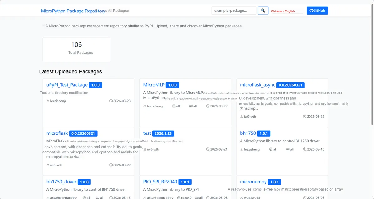
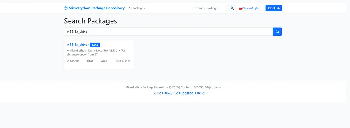
Enter vl53l1x_driver to search, and the following will be displayed:
Click to copy the local installation command:
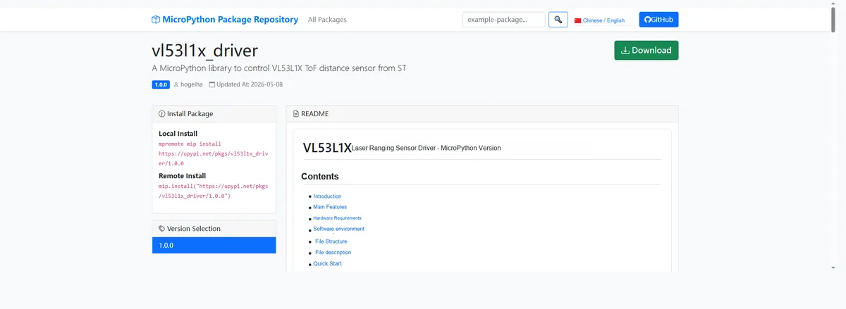
Import the module driver library code via the mip tool. Below are the usage commands for the mpremote tool:
mpremote mip install https://upypi.net/pkgs/vl53l1x_driver/1.0.0Import the MicroPython driver code for the VL53L1X-based laser ranging sensor module, then copy the following main.py code into our project:
# Python env   : MicroPython v1.23.0
# -*- coding: utf-8 -*-
# @Time    : 2026/05/06 07:00
# @Author  : FreakStudio
# @File    : main.py
# @Description : Code to test the VL53L1X laser ranging sensor driver class
# @License : MIT

# ======================================== Import Modules =========================================

import time
from machine import Pin, SoftI2C
from vl53l1x import VL53L1X

# ======================================== Global Variables ============================================

TARGET_SENSOR_ADDRS = [0x29]
I2C_SCL_PIN = 5
I2C_SDA_PIN = 4
I2C_FREQ = 400_000

# ======================================== Functions ============================================

# ======================================== Custom Classes ============================================

# ======================================== Initialization ==========================================

time.sleep(3)
print("FreakStudio: Using VL53L1X ToF distance sensor ...")

# Initialize the software I2C bus
i2c_bus = SoftI2C(sda=Pin(I2C_SDA_PIN), scl=Pin(I2C_SCL_PIN), freq=I2C_FREQ)

# Scan for devices on the I2C bus
devices_list = i2c_bus.scan()
print("START I2C SCANNER")
if len(devices_list) == 0:
    raise RuntimeError("I2C scan found no devices")
print("I2C devices found: %d" % len(devices_list))

# Iterate over the scan results and initialize the target sensor
sensor = None
for device in devices_list:
    if device in TARGET_SENSOR_ADDRS:
        print("I2C address: %s" % hex(device))
        sensor = VL53L1X(i2c=i2c_bus, address=device)
        print("Sensor initialization successful")
        break

if sensor is None:
    raise RuntimeError("No target sensor found on I2C bus")

# ========================================  Main Program  ===========================================

try:
    while True:
        distance_mm = sensor.read()
        print("Range: %d mm" % distance_mm)
        time.sleep_ms(50)

except KeyboardInterrupt:
    print("Program interrupted by user")
except OSError as e:
    print("Hardware communication error: %s" % str(e))
except Exception as e:
    print("Unknown error: %s" % str(e))
finally:
    print("Cleaning up resources...")
    sensor.deinit()
    del sensor
    print("Program exited")
Burn the code, open the terminal, and the output is as follows:
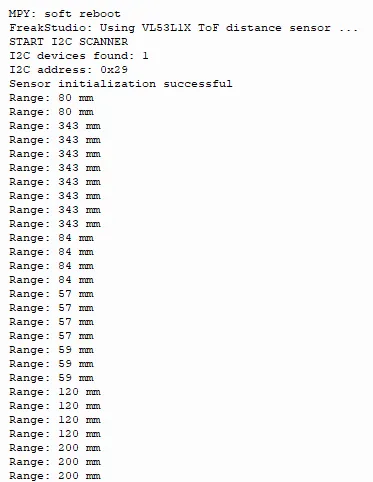
The VL53L1X TOF distance sensor features normal I2C communication and initialization, stably outputs distance data that updates in real time as the object moves closer or farther, delivers sensitive response, and works in proper condition.
IV. Drivers
vl53l1x_driver-1.0.0.zip 10 KB
5. BOM & Recommended Alternative Parts
None.
VI. Revision History
Document Version | Date of Revision | Modifier | Modify Content |
v1.0 | 2026-05-08 | Zero High-Luck | Initialize the document |
v1.1 | 2026-06-06 | Xin Ruili | Create an open version of the document based on the internal document version v1.0. |
VII. Relevant Materials
7.1 Chip Datasheet
vl53l1x.pdf 3.1 MB
7.2 Unique Icons for PCB Silk Screen