Contents
- I. Module Introduction
- II. Introduction to Main Chips
- 2.1 Chip Overview
- 2.2 Pin Definition
- 2.3 Functional Block Diagram
- 2.4 Performance Parameters
- 2.5 Reference Circuit
- 2.6 Chip Configuration
- 2.7 Communication Interfaces and Related Protocols
- 2.8 PCB Routing Precautions
- III. Circuit Engineering
- 3.1 Circuit Source Engineering
- 3.2 Module Usage Instructions
- 3.3 Application Experiment
- IV. Drivers
- 5. BOM & Recommended Alternative Parts
- VI. Revision History
- VII. Relevant Materials
- 7.1 Chip Datasheet
- 7.2 Unique Icons for PCB Silk Screen
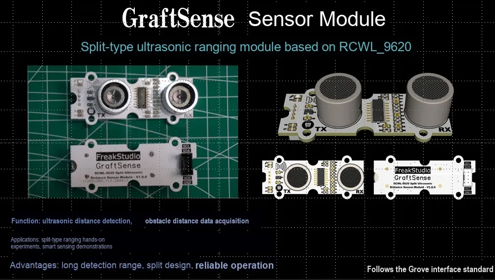
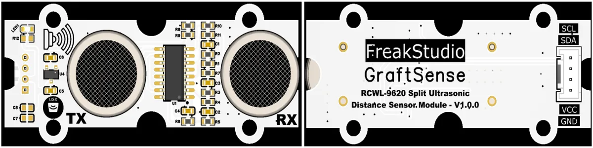
I. Module Introduction
Split Ultrasonic Ranging Module Based on RCWL-9620, which adopts the dedicated ranging chip solution of RCWL-9620, can independently complete the transmission, reception and distance calculation of 40kHz ultrasonic signals, supports wide-range detection from 2cm to 450cm, and achieves an accuracy of up to ±2%;The module is compatible with GPIO, UART, I²C, 1-Wire and other multi-interface outputs, adapts to a variety of split probes, and has built-in temperature compensation and blind zone elimination technology. It is powered by 5V and can communicate normally with 3.3V main control, with a static current of only 3mA, which is suitable for robot obstacle avoidance, liquid level detection, proximity sensing and other scenarios.
II. Introduction to Main Chips
RCWL-9620 is an ultrasonic ranging chip with an I2C interface. It features a ranging range of 2cm to 450cm, an accuracy of ±2%, 40kHz transmission and reception, and low power consumption of 3mA, making it suitable for short-range precise ranging and obstacle avoidance scenarios.
2.1 Chip Overview
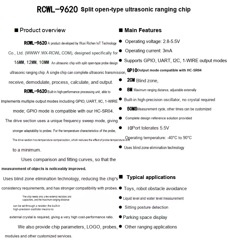
RCWL-9620 is a distance measurement chip specifically designed for split open ultrasonic probes, with an operating voltage of 2.8-5.5V, supporting GPIO, UART, IIC, 1-Wire and multiple other output modes, and compatible with the HC-SR04 protocol; it features a built-in high-precision oscillator and temperature compensation, adopts blind zone elimination technology, has a ranging blind zone of 2cm, a maximum range of up to 8m (externally adjustable), and an operating current of only 3mA, making it suitable for various ranging scenarios such as robot obstacle avoidance, liquid level detection, and parking space display.
2.2 Pin Definition
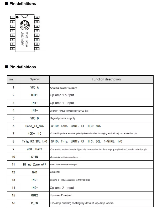
RCWL-9620 is an ultrasonic ranging chip in a 16-pin package: Pin 1 VCC_A is the analog power supply, Pin 5 VCC_D is the digital power supply, and Pin 12 GND is the ground pin. Among the communication control pins, Pin 6 Echo_TX_SDA supports GPIO (Echo)/ UART (TX)/ IIC (SDA) functions, and Pin 8 Trig_RX_SCL_I/O supports GPIO (Trig)/ UART (RX)/ IIC (SCL)/ 1-Wire (I/O) modes;Pin 7 40K+_IIC and Pin 9 40K-_UART are connected to the ultrasonic probe and also serve as mode selection pins; Pin 10 S-IN is the demodulated signal input, and Pin 11 Blind Zone oFF controls blind zone elimination; Pins 2/3/4 and Pins 13/14/15 are the input/output of the two operational amplifiers respectively, and Pin 16 P_EN is the operational amplifier enable pin, which works by default when left floating.
2.3 Functional Block Diagram
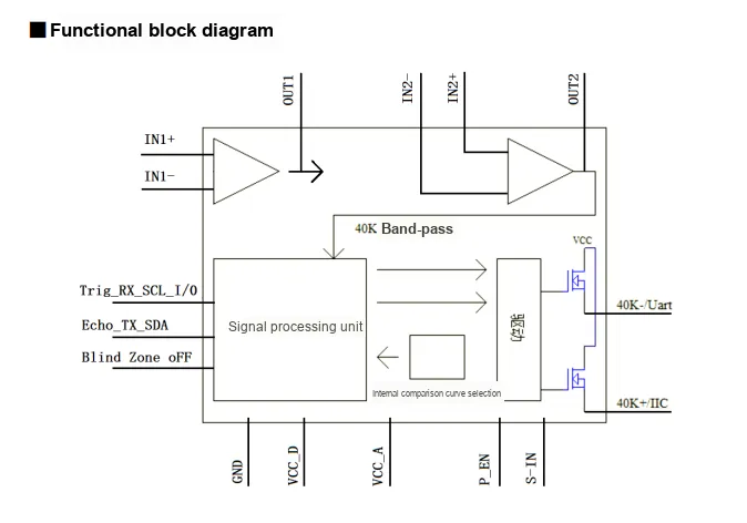
RCWL-9620 operates on the following core principle: the signal processing unit receives main control commands and outputs ranging results via the Trig_RX_SCL_I/O and Echo_TX_SDA interfaces, and drives, through the drive circuit, the ultrasonic probe connected to the 40K + and 40K - pins to transmit 40kHz sound waves; the reflected signal is demodulated and input via S-IN, filtered by a 40K band-pass filter and then sent to the signal processing unit, where the distance is calculated through internal comparison curve selection and blind zone elimination algorithm. Meanwhile, the two on-chip integrated operational amplifier units can condition and amplify external signals, with the P_EN pin controlling the op-amp enable. Powered by the dual power supplies of VCC_A and VCC_D, the module completes the entire ranging process from transmission, reception, processing to output.
2.4 Performance Parameters
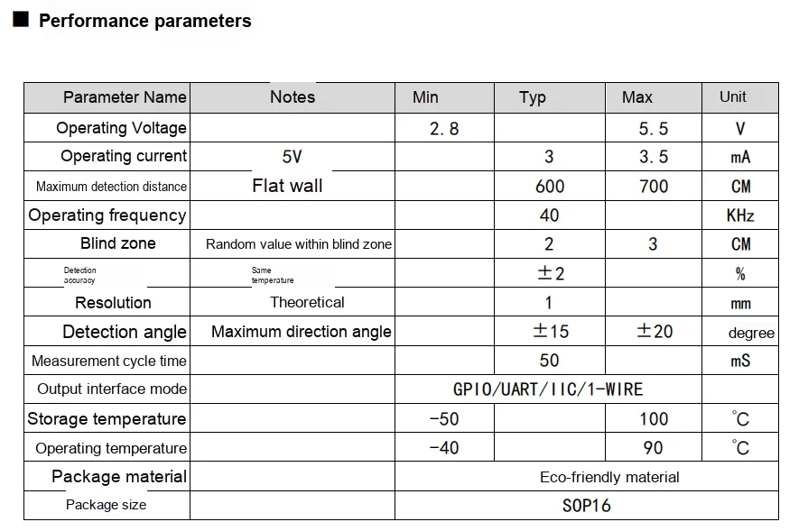
RCWL-9620 Operating voltage: 2.8~5.5V, operating current at 5V is only 3~3.5mA, typical ranging range: 2~600cm (max. 700cm), operating frequency: 40kHz, blind zone: 2~3cm, detection accuracy: ±2%, theoretical resolution: 1mm, detection angle: ±15°~±20°, single measurement cycle: 50ms, supports GPIO / UART / IIC / 1-Wire four output modes, operating temperature: -40℃~90℃, adopts SOP16 eco-friendly package.
2.5 Reference Circuit
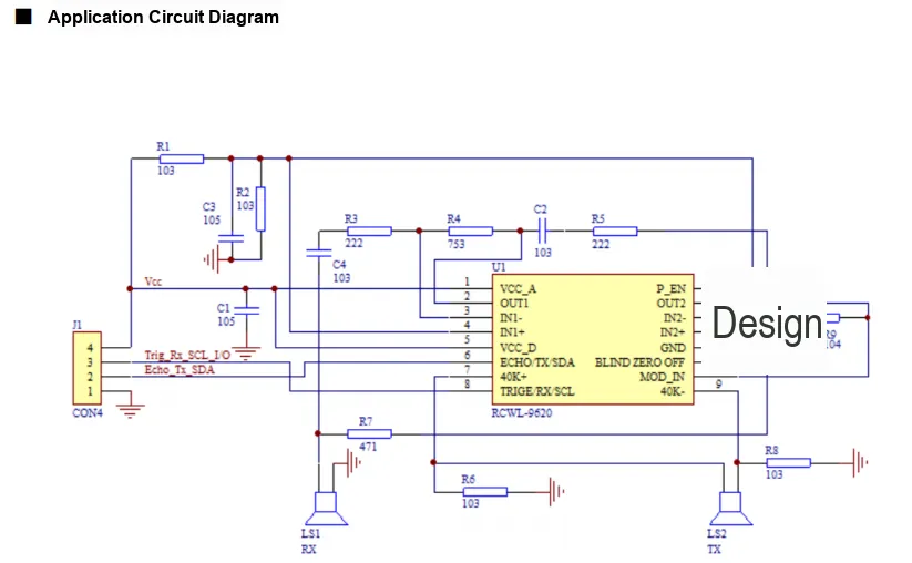
The power supply section performs filtering and voltage regulation via R1, R2 together with C1, C3, to supply power to the chip's VCC_A (analog power supply) and VCC_D (digital power supply);LS1 (receiving probe) and LS2 (transmitting probe) are respectively connected to pin 7 (40K+) and pin 9 (40K-) of the chip, with R7 and R8 serving as probe matching resistors; the chip's built-in signal conditioning operational amplifier, formed by R3, R4, R5, C2 and supporting peripheral circuits, is used to amplify the received signal.CON4 interface pins correspond respectively to Trig / Rx / SCL / I/O, Echo / Tx / SDA, which are used for communication with the main controller. Meanwhile, pin 11 BLIND ZERO OFF cooperates with pins such as pin 10 MOD_IN and the peripheral circuit to implement blind zone elimination and signal demodulation, finally completing the entire process of ultrasonic transmission, reception, processing and ranging data output.
2.6 Chip Configuration
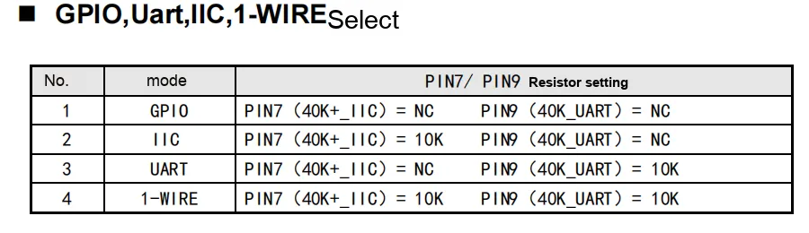
The communication mode of the RCWL-9620 is configured via external resistors on Pin 7 (40K+_IIC) and Pin 9 (40K-_UART). The specific selection method is as follows:
GPIOMode: Both pin 7 and pin 9 are left floating (NC), in which state the chip is compatible with theHC-SR04protocol and implements distance measurement via theTrig/Echopins.IICmode: Pin 7 is connected to a 10kΩ resistor, pin 9 is left floating, and theSDA/SCLpins are used forI2Ccommunication.UARTMode: Pin 7 is left floating, pin 9 is connected to a 10kΩ resistor, and serial port data is output via theTX/RXpins.1-WIREmode: Both pin 7 and pin 9 are connected to a 10kΩ resistor, and communicate with the main controller via the 1-Wire protocol.
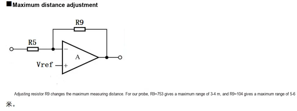
In the RCWL-9620 circuit, R9 serves as the feedback resistor of the operational amplifier — adjusting its resistance value can modify the amplification factor of the received signal, thereby controlling the maximum ranging distance:
R9= 753 (75kΩ): The amplification factor is relatively low, with a maximum ranging distance of approximately 3-4 meters, making it suitable for short-range scenarios with high anti-interference requirements.R9= 104 (100kΩ): Provides higher amplification factor, with a maximum ranging distance of 5-6 meters, making it suitable for scenarios requiring long-distance detection.
R9 The higher its resistance, the stronger the received signal amplification, and the longer the maximum detectable distance will be, but it will also be more susceptible to environmental noise.
2.7 Communication Interfaces and Related Protocols
2.7.1 GPIO Communication
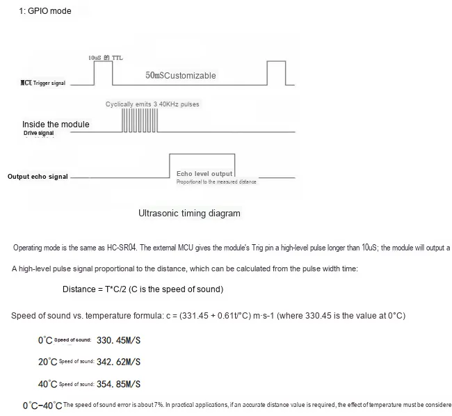
RCWL-9620 in GPIO mode is compatible with the HC-SR04 protocol, and its working process is as follows: The MCU sends a high-level pulse of ≥10µs to the Trig pin; the module internally drives the probe to emit 8 40kHz ultrasonic pulses, and after receiving the echo, outputs a high-level pulse width signal proportional to the distance via the Echo pin. The distance can be calculated using the formula Distance = Pulse width time T × Speed of sound C ÷ 2;The speed of sound is affected by temperature, and the formula is c=(331.45+ 0.61t/℃) m/s, with an error of approximately 7% between 0℃ and 40℃, so temperature compensation is required for high-precision applications.
2.7.2 UART Communication
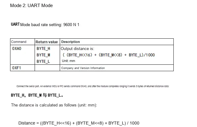
RCWL-9620 in UART mode has a default baud rate of 9600, N, 1; when an external MCU or PC sends the 0XA0 command, the module completes ranging and returns three bytes of data: BYTE_H, BYTE_M, and BYTE_L. The distance calculation formula is Distance =((BYTE_H << 16) +(BYTE_M << 8) + BYTE_L) / 1000, with the unit being millimeter; when the 0XF1 command is sent, the module returns manufacturer and version information.
2.7.3 UART Communication
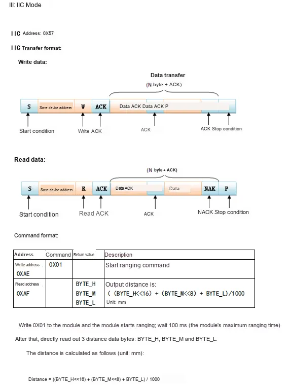
RCWL-9620 in IIC mode has a device address of 0X57, a write address of 0XAE, a read address of 0XAF, and its transmission follows the standard IIC start, acknowledge, and stop timings;After the host writes the 0X01 command to the module, the module starts ranging. After waiting for 100ms, read the three bytes BYTE_H, BYTE_M, and BYTE_L, then calculate the millimeter-level distance data through the formula Distance =((BYTE_H << 16) +(BYTE_M << 8) + BYTE_L) / 1000.
2.7.4 1-Wire Bus Communication
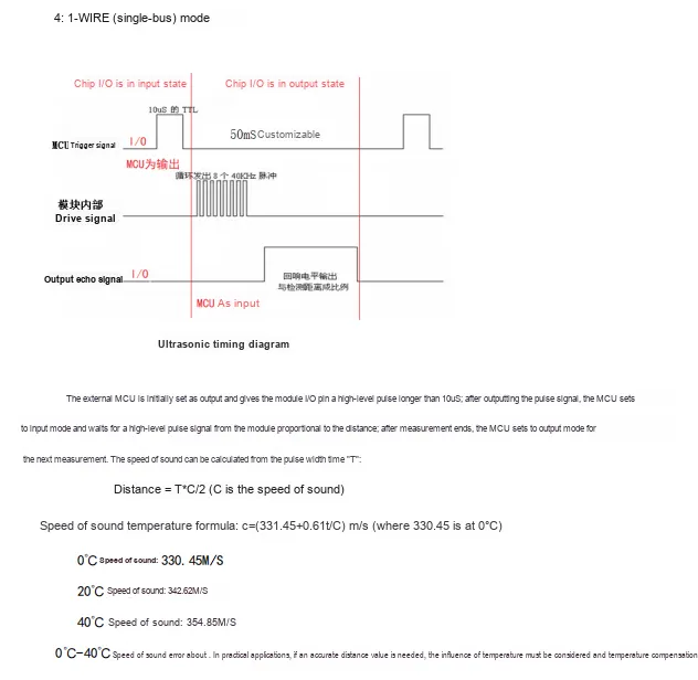
RCWL-9620 in 1-WIRE single-bus mode, the MCU needs to time-division multiplex the same I/O pin: first configure it as output to send a high-level trigger pulse of ≥10µs to the module; then switch to input, wait for the module to return an echo high-level pulse width signal proportional to the distance, and calculate the distance via the formula Distance = Pulse width time T × Speed of sound C ÷ 2. The speed of sound needs to be corrected according to the temperature formula c=(331.45+ 0.61t/℃) m/s; the speed of sound error is about 7% between 0℃ and 40℃, and temperature compensation is required for high-precision scenarios.
2.8 PCB Routing Precautions
None.
III. Circuit Engineering
3.1 Circuit Source Engineering
To obtain the circuit source project, please follow the official account [Freak Embedded]
3.2 Module Usage Instructions
The schematic diagram of this module is shown below:
SCH_Schematic1_Split-Type Ultrasonic Ranging Module Based on RCWL-9620_v1.0.0_2026-05-09.pdf 2.2 MB
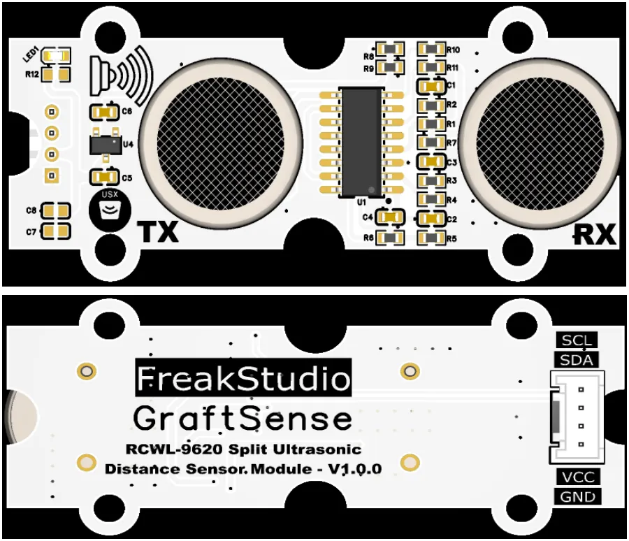
This module provides a IIC communication interface: it supports the standard I2C Communication Protocol, with a default device address of 0x57, and is compatible with 3.3V/5V level specifications. Through the SCL and SDA pins, it can realize the issuing of ranging commands and the reading of millimeter-level distance data. Cooperating with the RCWL-9620 chip, it completes the whole process interaction from ultrasonic transmission, echo reception to distance calculation, and is suitable for ranging scenarios that require stable digital interfaces such as robot obstacle avoidance, liquid level detection, and parking space sensing.
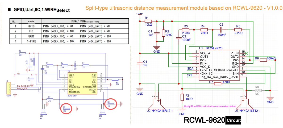
Here, it should be noted that R9 and R8 can be modified to other communication methods as required.
3.3 Application Experiment
Here, we use the GraftPort-RP2040 development board for testing, and the separate ultrasonic ranging module based on RCWL-9620 uses the I2C interface to communicate with the main controller.
Here, we first use the HY2.0-4P cable to connect the module to the GraftPort-RP2040 development board's I2C0 interface:
The module connections are shown in the following table:
development board pins | Module Pins | Description |
Pin 4 |
|
|
Pin 5 |
|
|
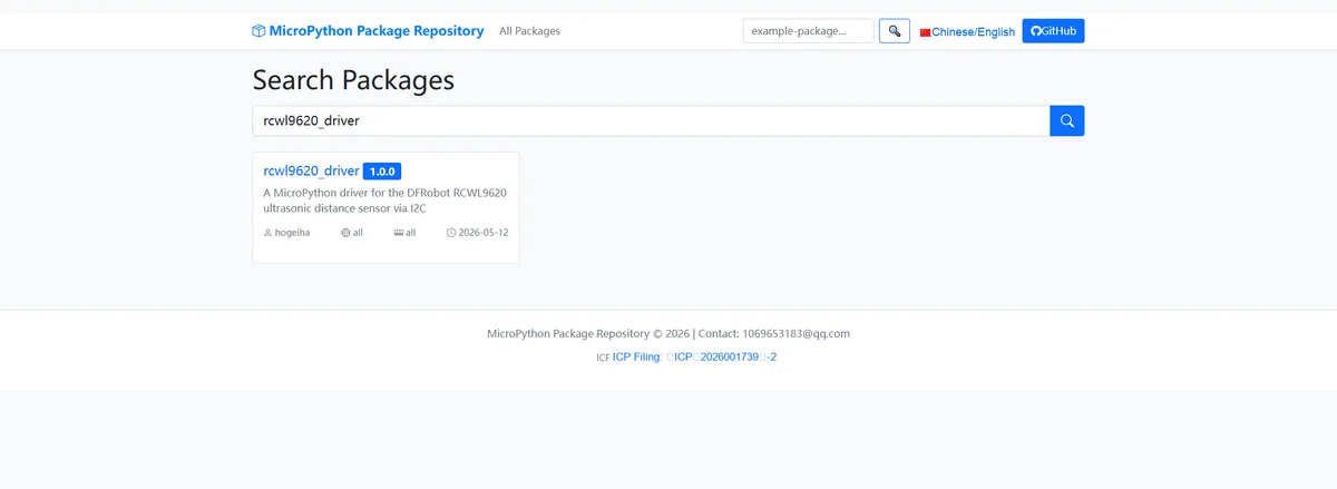
Here, we need to search for the relevant driver packages on uPyPI: https://upypi.net/zh/
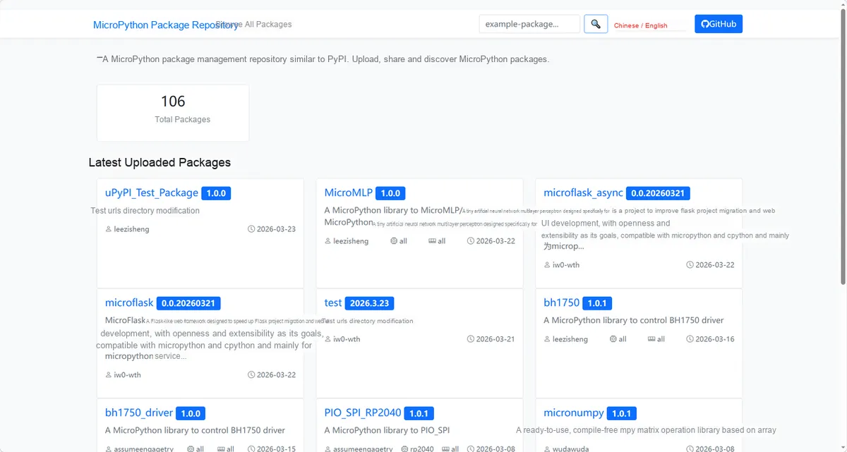
Enter rcwl9620_driver to search, and the following will be displayed:
Click to copy the local installation command:
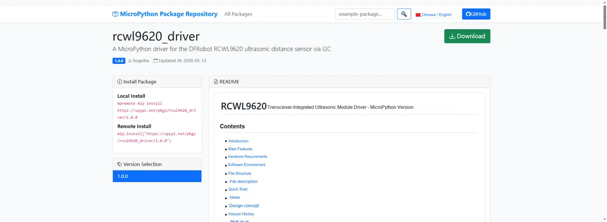
Import the module driver library code via the mip tool. Below are the usage commands for the mpremote tool:
mpremote mip install https://upypi.net/pkgs/rcwl9620_driver/1.0.0Import the separate ultrasonic ranging module based on RCWL-9620 - MicroPython driver code, then copy the following main.py code into our project:
# Python env   : MicroPython v1.23.0
# -*- coding: utf-8 -*-
# @Time    : 2026/05/06 00:00
# @Author  : DFRobot
# @File    : main.py
# @Description : Code for testing the RCWL9620 ultrasonic distance sensor driver class
# @License : MIT

# ======================================== Import Modules =========================================

import time
from machine import I2C, Pin
from rcwl9620 import RCWL9620

# ======================================== Global Variables ============================================

TARGET_SENSOR_ADDRS = [0x57]
I2C_ID = 0
I2C_SCL_PIN = 5
I2C_SDA_PIN = 4
I2C_FREQ = 100000
READ_INTERVAL_MS = 1000

# ======================================== Functions ============================================

# ======================================== Custom Classes ============================================

# ======================================== Initialization ==========================================

time.sleep(3)
print("FreakStudio: Using RCWL9620 ultrasonic distance sensor ...")

# Initialize the hardware I2C bus
i2c_bus = I2C(I2C_ID, sda=Pin(I2C_SDA_PIN), scl=Pin(I2C_SCL_PIN), freq=I2C_FREQ)

# Scan for devices on the I2C bus
devices_list = i2c_bus.scan()
print("START I2C SCANNER")
if len(devices_list) == 0:
    raise RuntimeError("I2C scan found no devices")
print("I2C devices found: %d" % len(devices_list))

# Iterate over the scan results and initialize the target sensor
sensor = None
for device in devices_list:
    if device in TARGET_SENSOR_ADDRS:
        print("I2C address: %s" % hex(device))
        sensor = RCWL9620(i2c=i2c_bus, address=device)
        print("Sensor initialization successful")
        break

if sensor is None:
    raise RuntimeError("No target sensor found on I2C bus")

# ========================================  Main Program  ===========================================

try:
    while True:
        distance_mm = sensor.read()
        print("Distance: %.2f mm" % distance_mm)
        time.sleep_ms(READ_INTERVAL_MS)

except KeyboardInterrupt:
    print("Program interrupted by user")
except OSError as e:
    print("Hardware communication error: %s" % str(e))
except Exception as e:
    print("Unknown error: %s" % str(e))
finally:
    print("Cleaning up resources...")
    sensor.deinit()
    del sensor
    print("Program exited")
Burn the code, open the terminal, and the output is as follows:
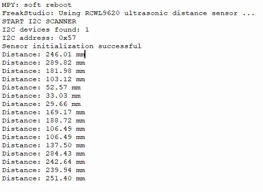
The RCWL9620 ultrasonic distance sensor features normal I2C communication and initialization, stably outputs distance data that updates in real time as objects move closer or farther, boasts sensitive response, and works in a normal operating state.
IV. Drivers
rcwl9620_driver-1.0.0.zip 8 KB
5. BOM & Recommended Alternative Parts
None.
VI. Revision History
Document Version | Date of Revision | Modifier | Modify Content |
v1.0 | 2026-05-09 | Zero High-Luck | Initialize the document |
v1.1 | 2026-06-06 | Xin Ruili | Create an open version of the document based on the internal document version v1.0. |
VII. Relevant Materials
7.1 Chip Datasheet
RCWL-9620-V1.0.pdf 520 KB
7.2 Unique Icons for PCB Silk Screen