Contents
- I. Module Introduction
- II. Introduction to Main Chips
- 2.1 Chip Overview
- 2.2 Pin Definition
- 2.3 Functional Block Diagram
- 2.4 Performance Parameters
- 2.5 Reference Circuit
- 2.6 Chip Configuration
- 2.7 Communication Interfaces and Related Protocols
- 2.8 PCB Routing Precautions
- III. Circuit Engineering
- 3.1 Circuit Source Engineering
- 3.2 Module Usage Instructions
- 3.3 Application Experiment
- IV. Drivers
- 5. BOM & Recommended Alternative Parts
- VI. Revision History
- 7. Relevant Materials
- 7.1 Chip Datasheet
- 7.2 Unique Icons for PCB Silk Screen
I. Module Introduction
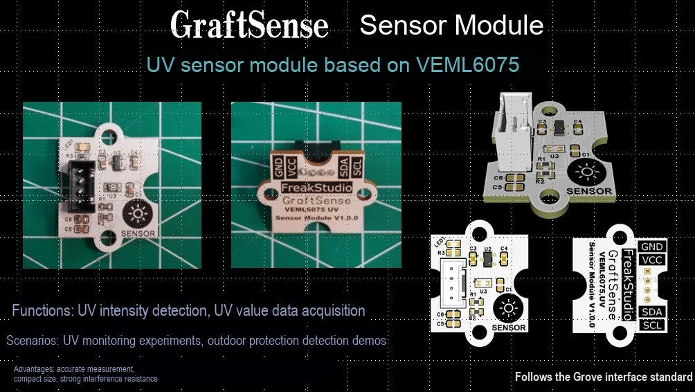
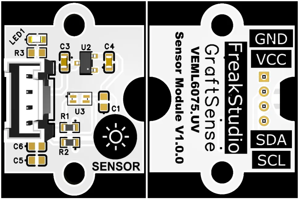
UV sensor module based on VEML6075, which adopts the Vishay VEML6075 dual-channel UVA / UVB UV sensor solution, integrates a 16-bit ADC and signal processing circuit, and can simultaneously detect the intensities of UVA and UVB and calculate the ultraviolet index UVI;The module is equipped with LDO voltage regulator circuits, power filtering and indicator light circuits, powered by 3.3V and communicating with the main controller via the I²C interface. It has built-in temperature compensation, delivers stable measurement in wide-temperature environments with low power consumption, and is suitable for scenarios such as outdoor monitoring, wearable devices, and portable and battery-powered equipment.
II. Introduction to Main Chips
VEML6075 is a Vishay -manufactured, I²C -interfaced, low-power 16-bit dual-channel UVA / UVB digital ultraviolet sensor that can calculate UVI with built-in temperature compensation.
2.1 Chip Overview
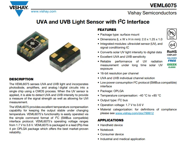
VEML6075 is Vishay 's integrated UVA / UVB ultraviolet sensor. Housed in an OPLGA package, it outputs 16-bit dual-channel digital data via the I²C / SMBus interface, featuring excellent temperature compensation and ultraviolet sensitivity. Operating at a supply voltage of 1.7~3.6V, it can be used to calculate the UVI index, and is suitable for handheld devices, consumer electronics, and industrial and medical applications.
2.2 Pin Definition
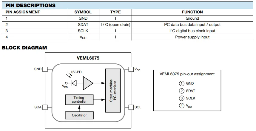
VEML6075 adopts a 4-pin package:
GND(Pin 1): Power GroundSDAT(Pin 2):I²Copen-drain data bus (bidirectional input/output)SCLK(Pin 3):I²CClock InputVDD(Pin 4): Power Supply Input (1.7~3.6V)
2.3 Functional Block Diagram
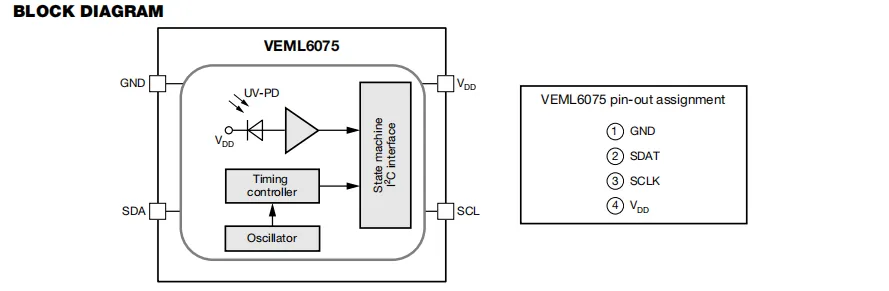
VEML6075 converts the incident UVA / UVB optical signals into electrical signals via its built-in ultraviolet photodiode (UV - PD ), which are then processed by the amplifier circuit and sent to the finite-state machine; the oscillator and timing controller provide clock and control signals, and finally the digital ultraviolet data is output to the main controller through the I²C interface (SDA / SCL). Its four pins are respectively responsible for the connection of power supply (VDD), ground (GND), I²C data (SDAT) and clock (SCLK).
2.4 Performance Parameters
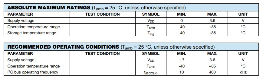
Absolute Maximum Ratings The maximum power supply voltage shall not exceed 3.6V, and both the operating and storage temperature ranges are -40℃ to + 85℃; exceeding these limits will damage the device.
Recommended Operating Conditions Power supply voltage: 1.7~3.6V, temperature: -40℃~+ 85℃, I²C bus clock frequency: 10~400kHz; stable performance can only be guaranteed within these ranges.
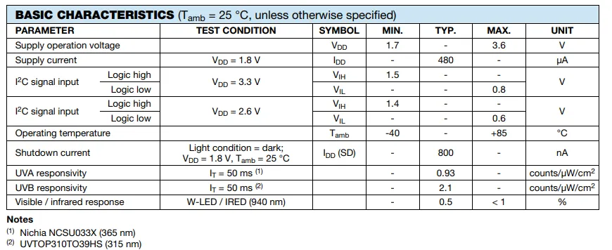
VEML6075 basic electrical and optical characteristics table: operating voltage 1.7-3.6V, typical operating current 480μA at 1.8V supply, shutdown current as low as 800nA;I²C input high and low levels adapt to the supply voltage, UVA / UVB responsivity is 0.93 and 2.1 counts/μW/cm² respectively, visible light / infrared rejection rate is lower than 1%, operating temperature range -40~+ 85℃.
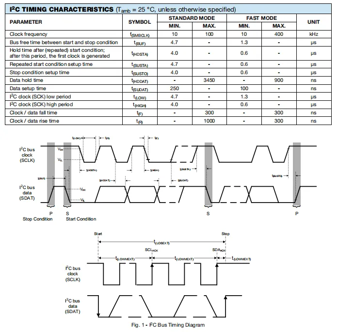
VEML6075 I²C timing characteristics define key parameters such as clock frequency, bus idle time, setup and hold times for start/stop conditions, and data setup/hold times in both standard mode (max 100kHz) and fast mode (max 400kHz), and illustrate via waveform diagrams the timing relationship between SCL clock and SDA data under start, repeated start, and stop conditions to ensure compliance with communication timing requirements.
2.5 Reference Circuit
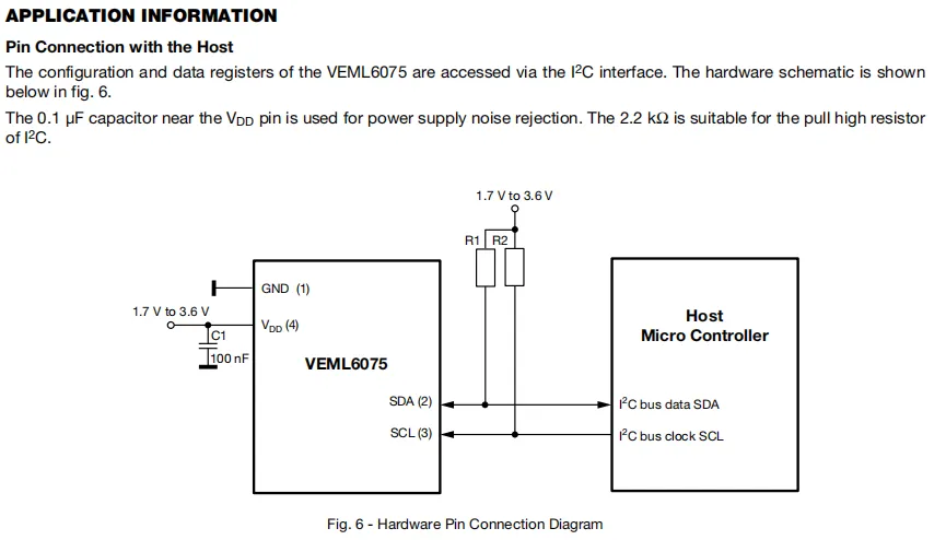
VEML6075 ultraviolet sensor communicates with the host via the I²C bus (SDA / SCL). A 100nF capacitor is connected to the power supply pin to filter noise, and a 2.2kΩ pull-up resistor is connected to each of the SDA / SCL lines to meet the voltage level requirements for I²C open-drain output. The host reads and writes the sensor configuration and ultraviolet data through this interface.
2.6 Chip Configuration
None.
2.7 Communication Interfaces and Related Protocols
2.7.1 I2C Communication
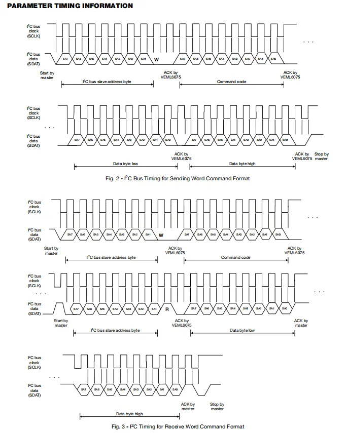
VEML6075 During write operations, the master sends the slave address and command code, followed by low/high byte data, and the device responds with ACK after each data transmission; for read operations, the slave address and command code are written first, then the address is sent in read mode to receive the low/high byte data returned by the device, and finally the master responds with ACK to terminate the communication. The entire process synchronizes data (SDAT) transmission via the clock (SCLK).
2.7.2 Registers
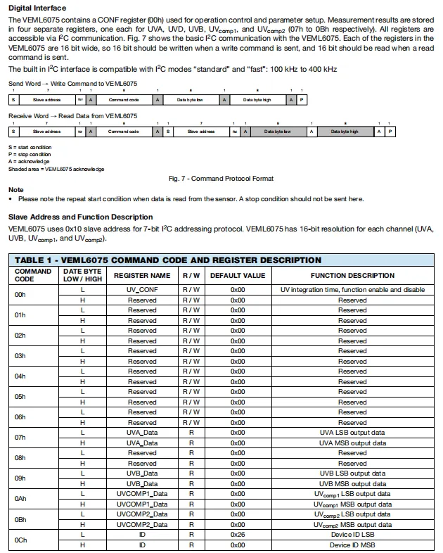
The VEML6075 chip adopts a 7-bit address 0x10, supports standard/fast I²C mode. All its registers are 16-bit, requiring double-byte transmission in accordance with the write/read command format. The configuration register 0x00 is used for function control, the measurement results (UVA / UVB and compensation data) are stored in 0x07 - 0x0Bh, and the device ID can be read via 0x0Ch.
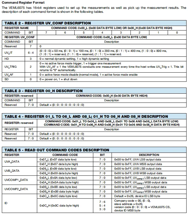
VEML6075 configuration register UV_CONF (0x00) has its low byte controlling the integration time (UV_IT), dynamic range (HD), trigger mode (UV_TRIG), active mode (UV_AF) and power switch (SD), while the high byte is reserved;Registers 0x01 to 0x06 and 0x08 are reserved bits.Measurement Result Registers UVA_DATA, UVB_DATA, UVCOMP1 / 2_DATA store the low/high byte data of the corresponding channels respectively, and the device ID register 0x0C contains the company code, slave address and version information.
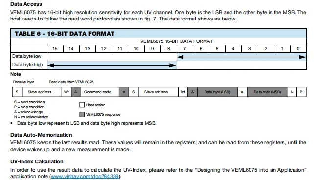
VEML6075 Data Access Instructions: The 16-bit data of each UV channel is divided into the least significant byte (LSB) and the most significant byte (MSB), which the host needs to read via the I²C word read protocol; the device will automatically store the last measurement result until a new measurement is completed; the final UV index calculation shall refer to the official application note.
2.8 PCB Routing Precautions
None.
III. Circuit Engineering
3.1 Circuit Source Engineering
To obtain the source code of the circuit, please follow the official account [Freak Embedded]
3.2 Module Usage Instructions
The schematic diagram of this module is shown below:
SCH_Schematic1_VEML6075-based UV sensor module_v1.0.0_2026-05-11.pdf 2.1 MB
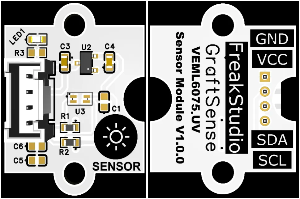
This module provides an I2C communication interface: it is compatible with standard/fast I2C modes (100~400kHz), adopts a fixed slave address 0x10, supports 3.3V level communication, and can stably read and write sensor configuration registers and 16-bit UVA / UVB measurement data. Combined with the onboard power filter circuit, it can provide reliable ultraviolet data interaction and detection capabilities for scenarios such as outdoor monitoring and wearable devices.
3.3 Application Experiment
Here, we use the GraftPort-RP2040 development board for testing, and the VEML6075-based ultraviolet sensor module uses the I2C interface to communicate with the main controller.
Here, we first use the HY2.0-4P cable to connect the module to the GraftPort-RP2040 development board's I2C0 interface:
The module connections are shown in the following table:
Development Board Pins | Module Pins | Description |
Pin 4 |
|
|
Pin 5 |
|
|
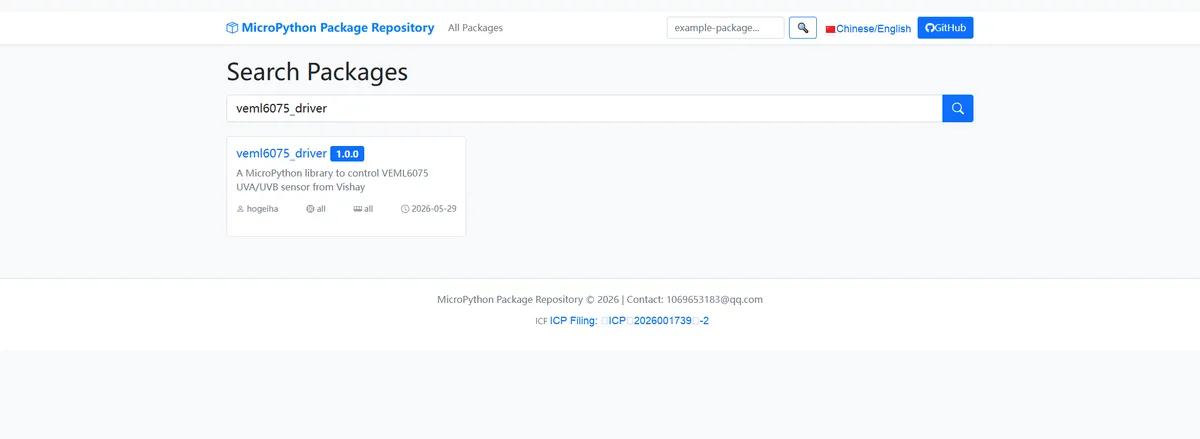
Here, we need to search for the relevant driver packages on uPyPI: https://upypi.net/zh/
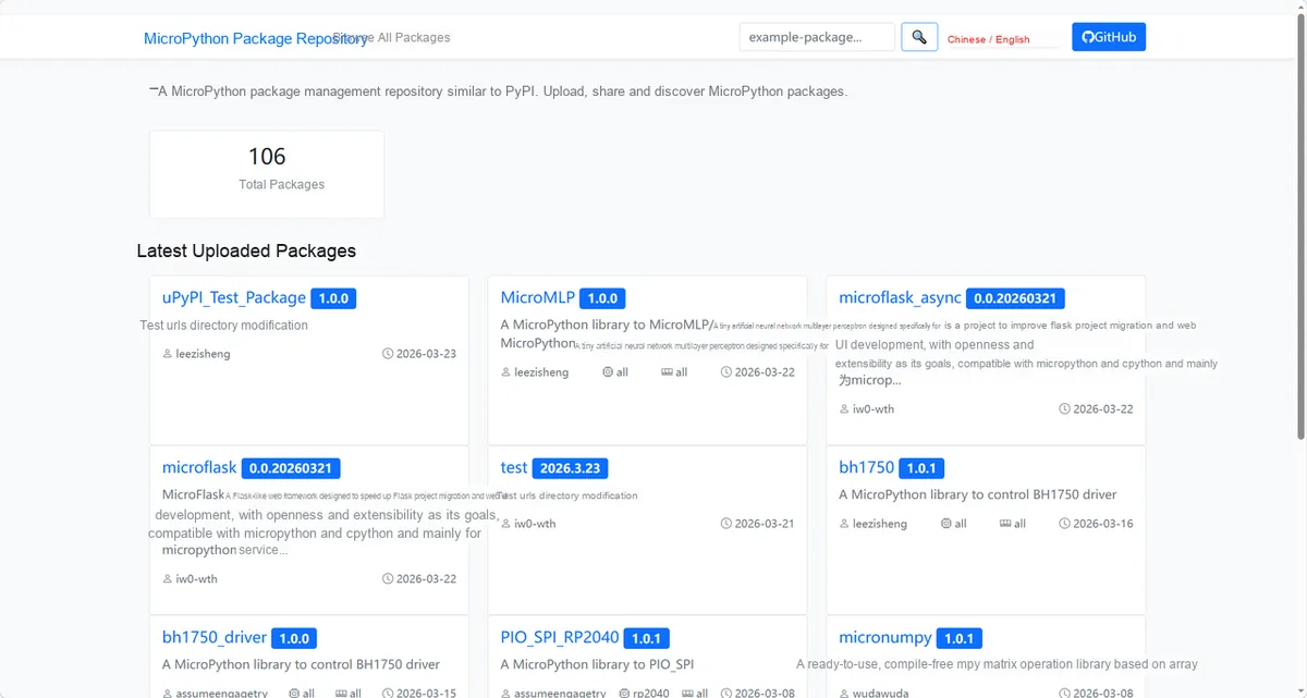
Enter veml6075_driver to search, and the following will be displayed:
Click to copy the local installation command:
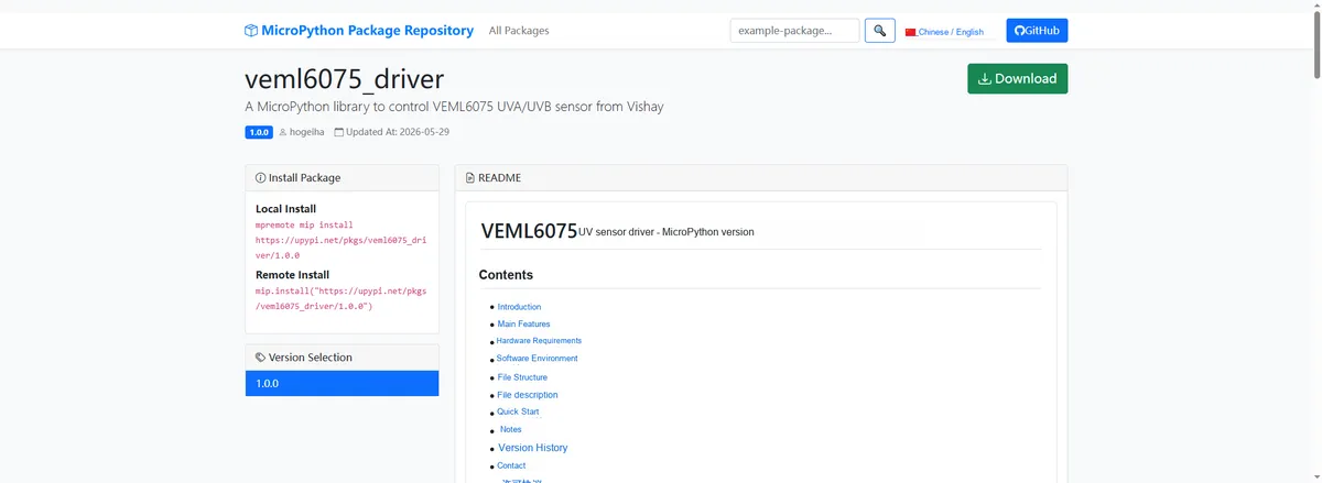
Import the module driver library code via the mip tool. Below are the usage commands for the mpremote tool:
mpremote mip install https://upypi.net/pkgs/veml6075_driver/1.0.0Import the UV sensor module based on VEML6075 - MicroPython driver code, then copy the following main.py code into our project:
# Python env   : MicroPython v1.23.0
# -*- coding: utf-8 -*-
# @Time    : 2026/05/06 09:00
# @Author  : Nelio Goncalves Godoi

# @File    : main.py
# @Description : Code to test the VEML6075 UV sensor driver class
# @License : MIT

# ======================================== Import Modules =========================================

import time
from machine import Pin, SoftI2C
from veml6075 import VEML6075

# ======================================== Global Variables ============================================

TARGET_SENSOR_ADDRS = [0x10]
I2C_SCL_PIN = 5
I2C_SDA_PIN = 4
I2C_FREQ = 100_000

# ======================================== Functions ============================================

# ======================================== Custom Classes ============================================

# ======================================== Initialization ==========================================

time.sleep(3)
print("FreakStudio: Using VEML6075 UV sensor ...")

# Initialize software I2C bus
i2c_bus = SoftI2C(sda=Pin(I2C_SDA_PIN), scl=Pin(I2C_SCL_PIN), freq=I2C_FREQ)

# Scan I2C bus devices
devices_list = i2c_bus.scan()
print("START I2C SCANNER")
if len(devices_list) == 0:
    raise RuntimeError("I2C scan found no devices")
print("I2C devices found: %d" % len(devices_list))

# Iterate over the scan results and initialize the target sensor
sensor = None
for device in devices_list:
    if device in TARGET_SENSOR_ADDRS:
        print("I2C address: %s" % hex(device))
        sensor = VEML6075(i2c=i2c_bus)
        print("Sensor initialization successful")
        break

if sensor is None:
    raise RuntimeError("No target sensor found on I2C bus")

# ========================================  Main Program  ===========================================

try:
    while True:
        print("UVA: %.2f" % sensor.uva)
        print("UV Index: %.2f" % sensor.uv_index)
        print("Integration time: %d ms" % sensor.integration_time)
        print("---")
        time.sleep_ms(1000)

except KeyboardInterrupt:
    print("Program interrupted by user")
except OSError as e:
    print("Hardware communication error: %s" % str(e))
except Exception as e:
    print("Unknown error: %s" % str(e))
finally:
    print("Cleaning up resources...")
    sensor.deinit()
    del sensor
    print("Program exited")
Burn the code, open the terminal, and the output is as follows:
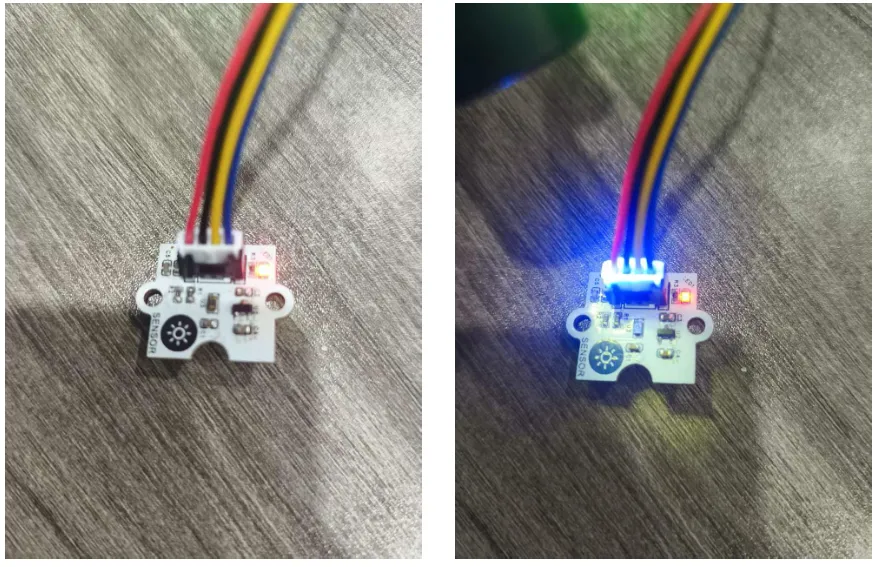
Irradiate the sensor with an ultraviolet lamp:
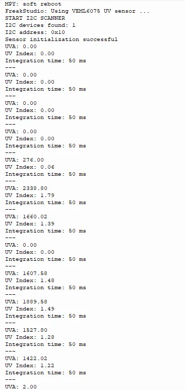
The VEML6075 ultraviolet sensor functions properly in I2C communication and initialization, and the ambient ultraviolet light intensity has been successfully read and printed on the terminal.
IV. Drivers
veml6075_driver-1.0.0.zip 8 KB
5. BOM & Recommended Alternative Parts
None.
VI. Revision History
Document Version | Date Modified | Modifier | Modify Content |
v1.0 | 2026-05-11 | Ling Gaoxing | Initialize the document |
v1.1 | 2026-06-05 | Xin Ruili | Create an open version of the document based on the internal document version v1.1. |
7. Relevant Materials
7.1 Chip Datasheet
VEML6075.pdf 454 KB
7.2 Unique Icons for PCB Silk Screen