Contents
- I. Module Introduction
- II. Introduction to Main Chips
- 2.1 Chip Overview
- 2.2 Pin Definition
- 2.3 Functional Block Diagram
- 2.4 Performance Parameters
- 2.5 Reference Circuit
- 2.6 Chip Configuration
- 2.7 Communication Interfaces and Related Protocols
- 2.8 PCB Routing Precautions
- III. Circuit Engineering
- 3.1 Circuit Source Engineering
- 3.2 Module Usage Instructions
- 3.3 Application Experiment
- IV. Drivers
- 5. BOM & Recommended Alternative Parts
- VI. Revision History
- 7. Relevant Materials
- 7.1 Chip Datasheet
- 7.2 Unique Icons for PCB Silk Screen
I. Module Introduction
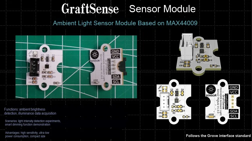
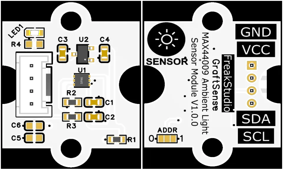
Ambient light sensor module based on MAX44009, which adopts the MAX44009 high-precision digital ambient light sensor solution, has a built-in ADC and digital processing unit, and can directly output illumination intensity data;The module is equipped with an address selection circuit, LDO voltage regulator circuit, power filtering and indicator circuit. It is powered by 3.3V and communicates with the main control via the I²C interface. With a measurement range covering 0.045lux to 188000lux, it eliminates the need for manual range switching, features ultra-low power consumption, supports interrupt triggering, and is suitable for low-power application scenarios such as automatic screen dimming, smart homes, and portable devices.
II. Introduction to Main Chips
MAX44009 is a product of Maxim (ADI) ultra-low power ambient light sensor, with built-in ADC and I²C interface, a current draw of only 0.65μA, an illumination range of 0.045–188,000 lux, and is suitable for portable devices.
2.1 Chip Overview
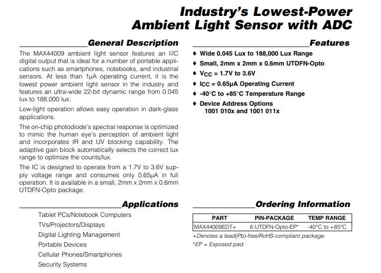
MAX44009 is an ultra-low-power ambient light sensor with an operating current of only 0.65μA, supporting a wide measurement range of 0.045 to 188000 lux. Its spectral response mimics the human eye with built-in infrared and ultraviolet shielding, and it features an I²C interface, operates on a supply voltage of 1.7 to 3.6V, making it ideal for applications such as portable devices and display backlight adjustment.
2.2 Pin Definition
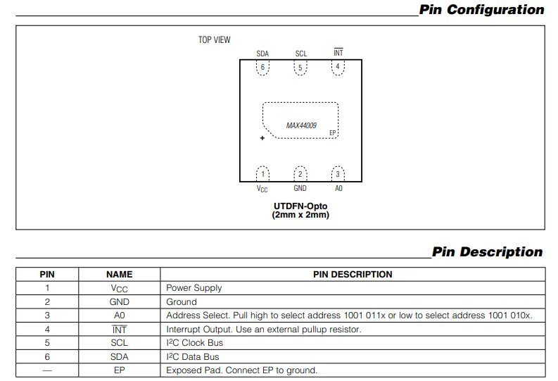
MAX44009 in its 6-pin UTDFN package: Pin 1 VCC is for power supply, Pin 2 GND is for ground, Pin 3 A0 serves for I²C address selection, Pin 4 INT is an open-drain interrupt output (requires an external pull-up resistor), Pins 5 and 6 are respectively the I²C clock SCL and data SDA, and the exposed pad at the bottom EP must be connected to ground.
2.3 Functional Block Diagram
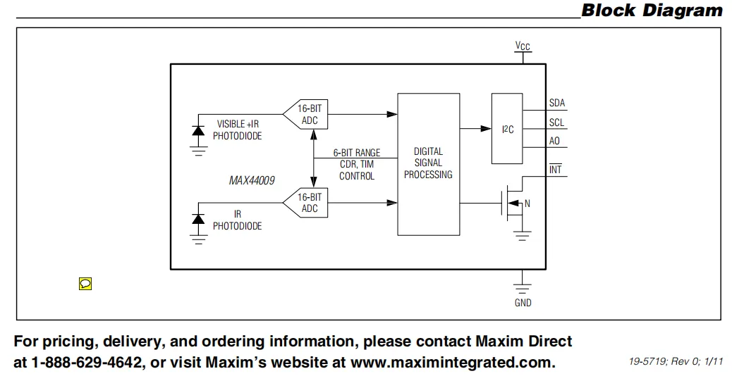
MAX44009 collects the optical signals of visible light + infrared and pure infrared respectively through a dual-channel photodiode, and after being converted by a 16-bit ADC, the signals are sent to the Digital Signal Processing unit, the control logic automatically adjusts the measurement range and timing, and finally outputs the illuminance data through the I²C interface. It also integrates an open-drain interrupt output, which can trigger a signal when the light exceeds the threshold.
2.4 Performance Parameters
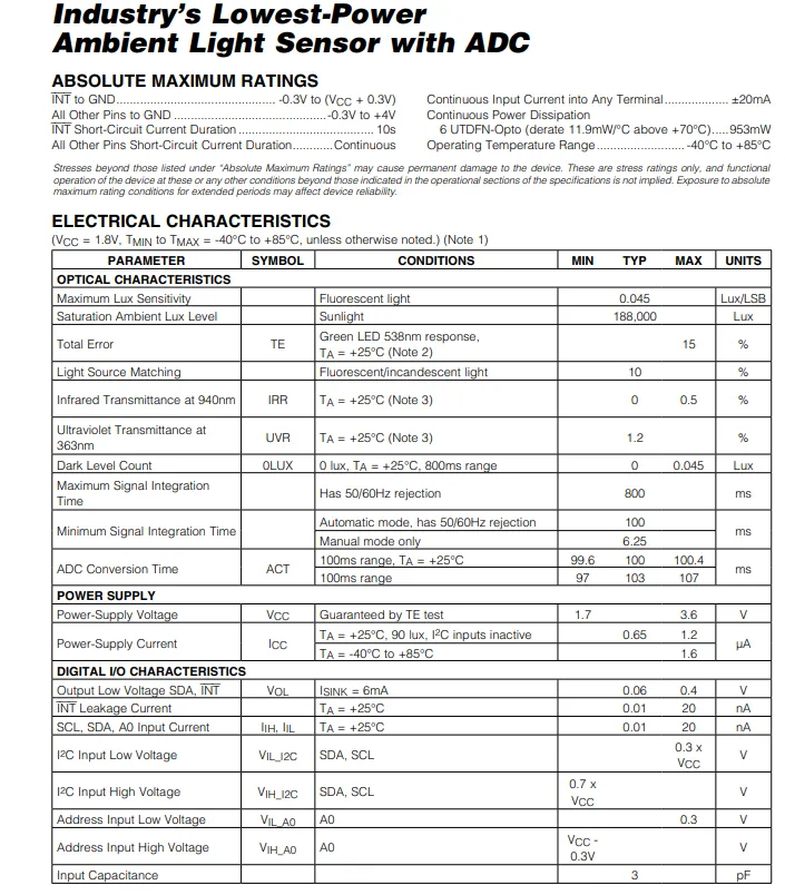
MAX44009 has an absolute maximum rated supply voltage of 1.7~3.6V, a typical operating current of only 0.65μA, an illuminance range of 0.045~188000lux, supports automatic/manual integration time control, and has built-in 50/60Hz light source suppression; it also specifies key parameters including I²C interface level, interrupt pin leakage current, input capacitance, etc. Exceeding the rated conditions may cause damage to the device.
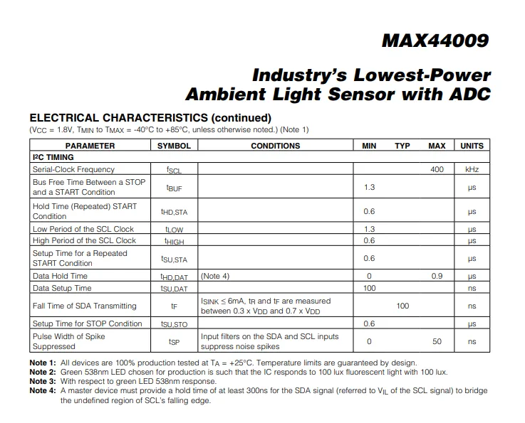
MAX44009 specifies the communication specifications under the conditions of 1.8V power supply and -40°C to + 85°C: the maximum clock frequency is 400kHz, and it also defines key parameters including bus idle time, setup and hold time for start/repeated start conditions, SCL high and low level periods, data setup/hold time, signal rise/fall time and noise suppression pulse width, which provides a design basis for the reliable timing of I²C bus communication.
2.5 Reference Circuit
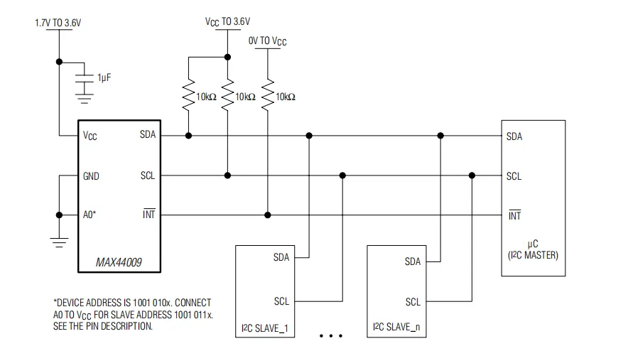
Power is supplied by a 1.7~3.6V power source after being filtered through a 1μF capacitor. I²C bus (SDA / SCL) and the open-drain interrupt pin (INT) are both pulled high via 10kΩ pull-up resistors. The A0 pin can be connected to ground or VCC to configure different I²C addresses, allowing multiple I²C devices to be connected to the same bus. The main controller reads the illuminance data via I²C, and the INT pin can trigger an interrupt to notify the main controller when the light intensity exceeds the threshold.
2.6 Chip Configuration
None.
2.7 Communication Interfaces and Related Protocols
2.7.1 I2C Communication
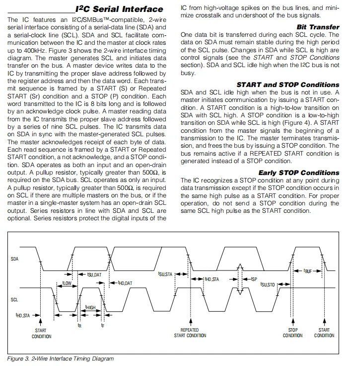
MAX44009 supports a maximum clock rate of 400kHz. SDA (bidirectional open-drain) and SCL (input-only) require external pull-up resistors, and bus communication is managed via start / repeated start / stop conditions. Data remains stable while SCL is at high level and changes while SCL is at low level. The Sequence Diagram clearly marks key parameters such as setup time, hold time, high and low level periods to ensure reliable communication.
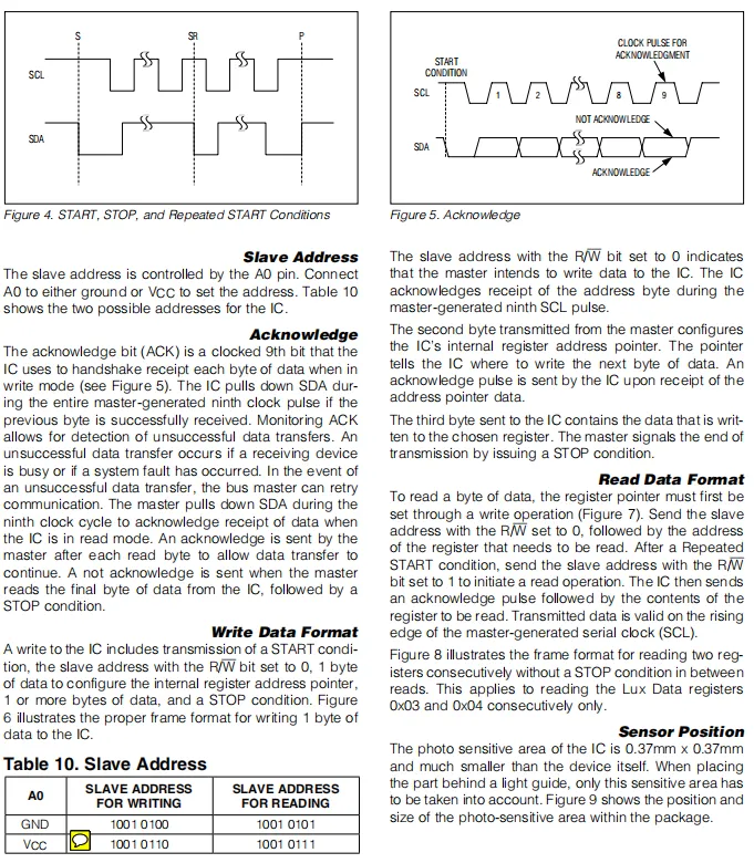
MAX44009 's I²C interface allows setting two slave addresses via the level of the A0 pin, and communication relies on start/repeated start/stop conditions and acknowledge bits for handshaking; for write operations, you need to first send the address + register pointer before transmitting data, while for read operations, you must first write the register pointer and then switch to read mode with a repeated start.
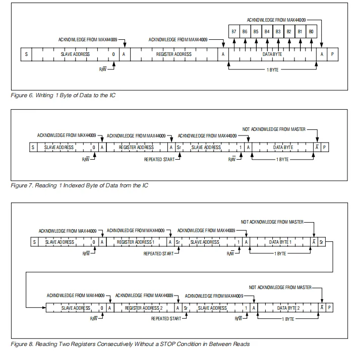
MAX44009 supports single-byte write operations, which require sequentially sending a start signal, a write address, a register address, and data; for a single-byte read, the address and register pointer must be written first, then the mode is switched to read via a repeated start; for continuous read operations, after reading the first register, the address is directly switched via a repeated start to achieve multi-register reading without a stop condition, and the communication status is confirmed by acknowledge bits throughout the process.
2.7.2 Registers
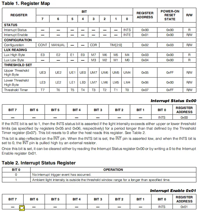
MAX44009 's STATUS (0x00) and INTERRUPT ENABLE (0x01) registers are used for interrupt status reading and enable configuration;CONFIGURATION (0x02) controls the operating mode and integration time;LUX READING (0x03 / 0x04) stores illuminance data;THRESHOLD SET (0x05 / 0x06 / 0x07) sets the interrupt trigger threshold and delay time, and after an interrupt is triggered, it can be reset by reading the STATUS register or clearing the enable bit.
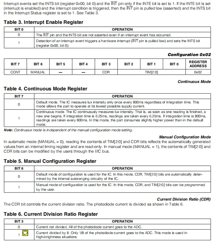
MAX44009 Interrupt Enable Register (0x01) controls interrupt triggering via the INT bit; when enabled, an interrupt event pulls the INT pin low and sets the corresponding status bit. The 0x02 Configuration Register uses its CONT bit to select single/continuous measurement mode, the MANUAL bit to choose auto/manual ranging, the CDR bit to set the current division ratio (1/8 shunt for high brightness), and the TIM[2:0] bits to control integration time, enabling flexible configuration of power consumption and measurement accuracy.
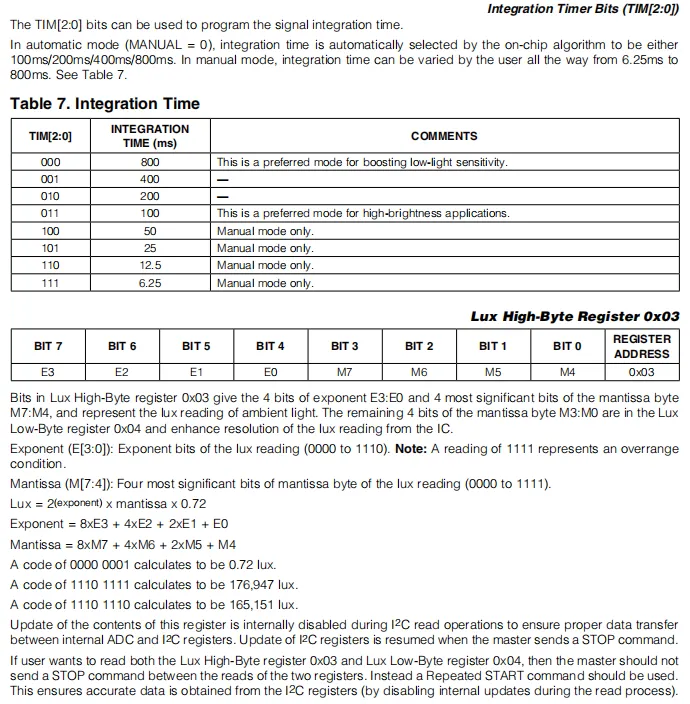
MAX44009 's TIM[2:0] bits configure the integration time: auto mode supports 100/200/400/800ms, while manual mode allows a minimum as low as 6.25ms; the illuminance data follows an exponent-mantissa format, where the high byte at 0x03 stores the exponent E and the upper 4 bits of the mantissa, and the low byte at 0x04 stores the lower 4 bits of the mantissa. The calculation formula is Lux = 2^(exponent) × mantissa × 0.72, and a repeated start signal must be used to read both bytes consecutively during reading to avoid interference from data updates.
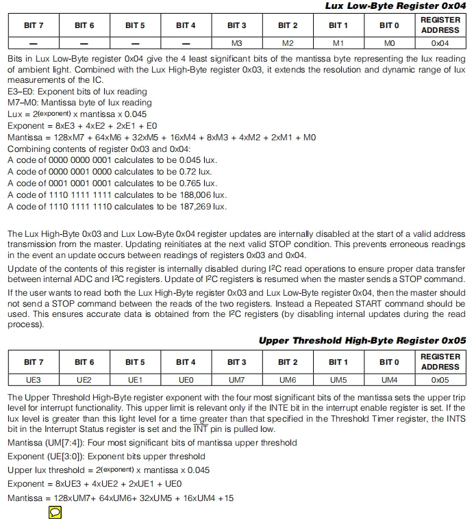
MAX44009 's 0x04 low-order byte stores the lower 4 bits of the illuminance mantissa, and combines with the 0x03 high-order byte to form an exponent-mantissa format; the illuminance is calculated according to the formula Lux = 2^(exponent) × mantissa × 0.045, and a repeated start signal is required when reading the two bytes consecutively to avoid interference from data updates;the 0x05 high threshold high-order byte stores the exponent and the upper 4 bits of the mantissa for the upper limit of interrupt trigger, which has the same format as the illuminance data and is used to configure the interrupt trigger condition when the illuminance is too high.
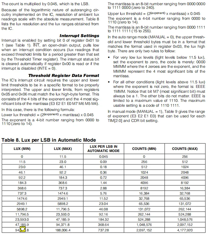
MAX44009 interrupt can be enabled by setting bit 0 of register 0x01, and the trigger condition is that the illuminance exceeds the threshold and lasts longer than the time set by the timer; the upper and lower threshold registers need to adopt the same exponent-mantissa format as the illuminance data, and the calculation formula is threshold = 2^(exponent) × mantissa × 0.045; in automatic mode, as the illuminance range increases, the illuminance value corresponding to each LSB also increases logarithmically, achieving a wide range coverage from 0.045lux to 188,006.4lux.
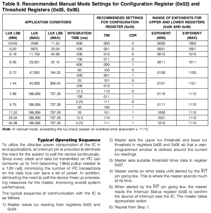
MAX44009 recommends manual mode configuration and typical workflow, which defines the integration time, CDR (current division ratio) and TIM parameter configuration under different illuminance ranges, as well as the corresponding threshold register exponent range; the typical workflow reads illuminance data via I²C, sets upper and lower thresholds and timers, and uses the interrupt pin to trigger notification to the main controller, avoiding polling to reduce power consumption and realizing ultra-low power operation.
2.8 PCB Routing Precautions
None.
III. Circuit Engineering
3.1 Circuit Source Engineering
To obtain the source code of the circuit, please follow the official account [Freak Embedded]
3.2 Module Usage Instructions
The schematic diagram of this module is shown below:
SCH_Schematic1_Ambient Light Sensor Module Based on MAX44009_v1.0.0_2026-05-11.pdf 2.1 MB
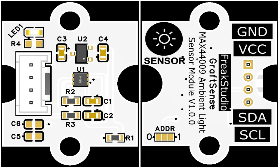
This module provides IIC communication interface: it supports standard I2C communication rate, and the ADDR pin allows flexible configuration of the I2C address. It is compatible with 3.3V level, and can stably transmit the wide-range illumination intensity digital signals ranging from 0.045 lux to 188000 lux collected by MAX44009. Suitable for low-power application scenarios such as automatic screen dimming, smart homes and portable devices, it provides the system with reliable and high-precision interactive capability for ambient light sensing data.
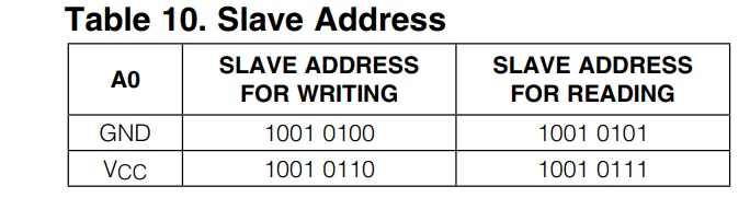
By setting the ADDR pin to connect to GND or VCC, different IIC addresses can be configured.
3.3 Application Experiment
Here, we use the GraftPort-RP2040 development board for testing, and the ambient light sensor module based on MAX44009 uses the I2C interface to communicate with the main controller.
Here, we first use the HY2.0-4P cable to connect the module to the GraftPort-RP2040 development board's I2C0 interface:
The module connections are shown in the following table:
Development Board Pins | Module Pins | Description |
Pin 4 |
|
|
Pin 5 |
|
|
Here, we need to search for the relevant driver packages on uPyPI: https://upypi.net/zh/
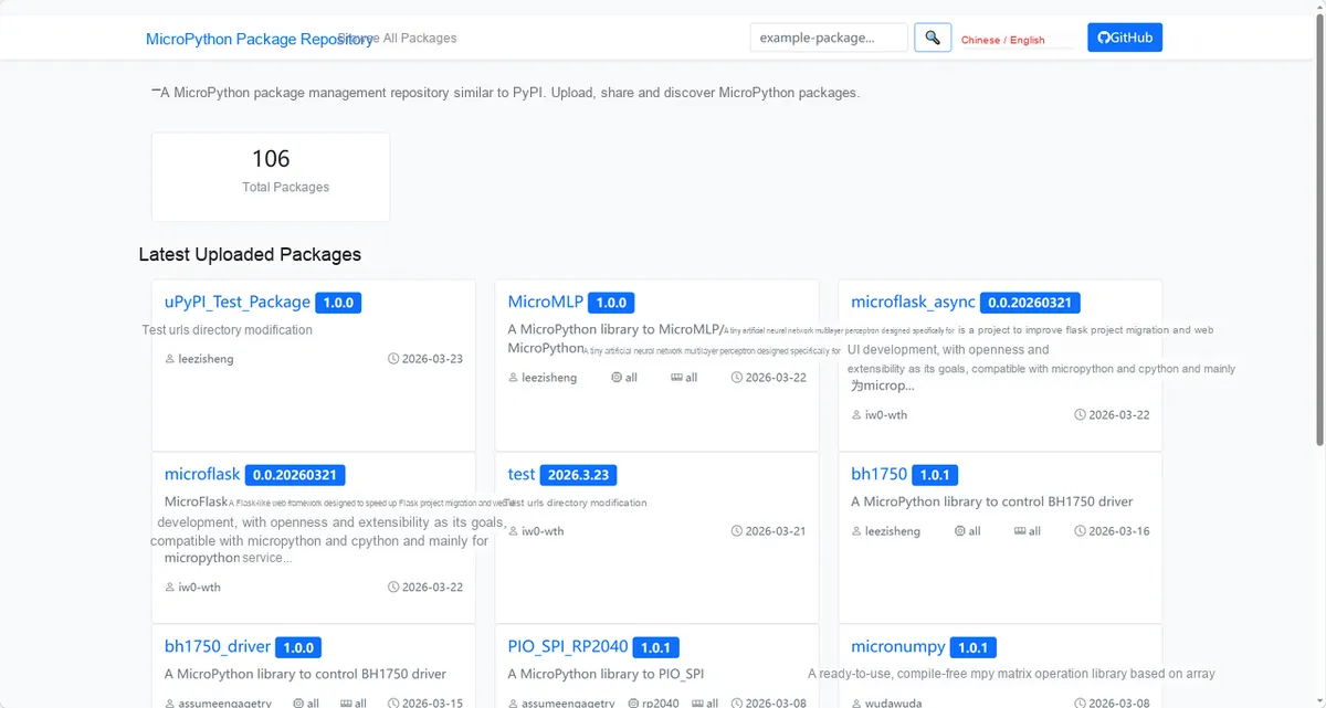
Enter max44009_driver to search, and the following will be displayed:

Click to copy the local installation command:
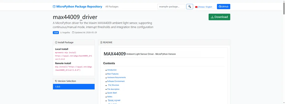
Import the module driver library code via the mip tool. Below are the usage commands for the mpremote tool:
mpremote mip install https://upypi.net/pkgs/max44009_driver/1.0.0Import the ambient light sensor module based on MAX44009 - MicroPython driver code, then copy the following main.py code into our project:
# Python env   : MicroPython v1.23.0
# -*- coding: utf-8 -*-
# @Time    : 2026/04/22 14:15
# @Author  : FreakStudio
# @File    : main.py
# @Description : Code to test the MAX44009 ambient light sensor driver class
# @License : MIT

# ======================================== Import Modules =========================================

from machine import I2C, Pin
from max44009 import MAX44009
import time

# ======================================== Global Variables ============================================

I2C_ID = 0
I2C_SDA_PIN = 4
I2C_SCL_PIN = 5
I2C_FREQ = 100000
MAX44009_ADDR_LIST = (0x4A, 0x4B)
I2C_MUX_ADDR = 0x70
I2C_MUX_CHANNELS = 8
READ_INTERVAL = 1

# ======================================== Functions ============================================

def find_sensor_address(i2c):
    """
    Find the I2C address of the MAX44009 sensor
    Args:
        i2c (I2C): I2C bus object
    Raises:
        RuntimeError: Sensor not found
    Notes:
        The MAX44009 address is determined by the A0 pin and may be 0x4A or 0x4B
    ==========================================
    Find MAX44009 sensor I2C address.
    Args:
        i2c (I2C): I2C bus object
    Raises:
        RuntimeError: Sensor not found
    Notes:
        MAX44009 address depends on A0 pin, can be 0x4A or 0x4B
    """
    devices = i2c.scan()
    print("Devices: %s" % str([hex(d) for d in devices]))
    for address in MAX44009_ADDR_LIST:
        if address in devices:
            return address
    raise RuntimeError("MAX44009 not found")


def select_mux_channel(i2c, channel):
    """
    Select a TCA9548A multiplexer channel
    Args:
        i2c (I2C): I2C bus object
        channel (int): Multiplexer channel
    Raises:
        ValueError: Invalid channel parameter
    Notes:
        No need to call this when a multiplexer is not used
    ==========================================
    Select TCA9548A multiplexer channel.
    Args:
        i2c (I2C): I2C bus object
        channel (int): Multiplexer channel
    Raises:
        ValueError: Channel parameter is invalid
    Notes:
        Not needed without multiplexer
    """
    if channel < 0 or channel >= I2C_MUX_CHANNELS:
        raise ValueError("Mux channel out of range")
    i2c.writeto(I2C_MUX_ADDR, bytes([1 << channel]))


def find_sensor_with_mux(i2c):
    """
    Find the MAX44009 sensor through an optional multiplexer
    Args:
        i2c (I2C): I2C bus object
    Raises:
        RuntimeError: Sensor not found
    Notes:
        If a device exists at 0x70 on the bus, try to handle it as a TCA9548A
    ==========================================
    Find MAX44009 sensor with optional multiplexer.
    Args:
        i2c (I2C): I2C bus object
    Raises:
        RuntimeError: Sensor not found
    Notes:
        If 0x70 exists on bus it is tried as TCA9548A
    """
    devices = i2c.scan()
    for address in MAX44009_ADDR_LIST:
        if address in devices:
            return address, None
    if I2C_MUX_ADDR not in devices:
        raise RuntimeError("MAX44009 not found")
    for channel in range(I2C_MUX_CHANNELS):
        select_mux_channel(i2c, channel)
        time.sleep_ms(10)
        channel_devices = i2c.scan()
        print("Mux channel %d devices: %s" % (channel, str([hex(d) for d in channel_devices])))
        for address in MAX44009_ADDR_LIST:
            if address in channel_devices:
                return address, channel
    i2c.writeto(I2C_MUX_ADDR, bytes([0x00]))
    raise RuntimeError("MAX44009 not found")


# ======================================== Custom Classes ============================================

# ======================================== Initialization ==========================================

time.sleep(3)
print("FreakStudio: Using MAX44009 ambient light sensor ...")

# Initialize the hardware I2C bus
i2c = I2C(I2C_ID, sda=Pin(I2C_SDA_PIN), scl=Pin(I2C_SCL_PIN), freq=I2C_FREQ)

# Automatically find the sensor I2C address (supports TCA9548A multiplexer)
sensor_address, mux_channel = find_sensor_with_mux(i2c)
print("MAX44009 address: 0x%02X" % sensor_address)
if mux_channel is not None:
    print("MAX44009 mux channel: %d" % mux_channel)

# Initialize the sensor object
sensor = MAX44009(i2c, address=sensor_address)

# Configure the sensor parameters
sensor.continuous = 1
sensor.manual = 0
sensor.current_division_ratio = 0
sensor.integration_time = 3
print("Configuration register: %d" % sensor._config)

# ========================================  Main Program  ===========================================

try:
    while True:
        lux = sensor.lux
        lux_fast = sensor.lux_fast
        int_status = sensor.int_status
        print("Lux: %.2f lx  Fast: %.2f lx  Interrupt: %d" % (lux, lux_fast, int_status))
        time.sleep(READ_INTERVAL)

except KeyboardInterrupt:
    print("Program interrupted by user")
except OSError as e:
    print("Hardware communication error: %s" % str(e))
except Exception as e:
    print("Unknown error: %s" % str(e))
finally:
    print("Cleaning up resources...")
    sensor.deinit()
    del sensor
    print("Program exited")
Burn the code, open the terminal, and the output is as follows:
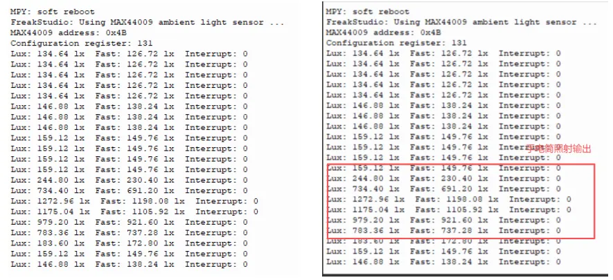
When illuminated by a flashlight, the illuminance value of the MAX44009 rapidly surges from approximately 134 lx to 1272.96 lx, with the Fast channel responding synchronously; after the light source is removed, the value quickly drops back to the ambient light level, the interrupt status remains 0 throughout, indicating that the sensor has sensitive response and stable data.
IV. Drivers
max44009_driver-1.0.0.zip 11 KB
5. BOM & Recommended Alternative Parts
None.
VI. Revision History
Document Version | Date Modified | Modifier | Modify Content |
v1.0 | 2026-05-11 | Ling Gaoxing | Initialize the document |
v1.1 | 2026-06-06 | Xin Ruili | Create an open version of the document based on the internal document version v1.0. |
7. Relevant Materials
7.1 Chip Datasheet
MAX44009.pdf 1014 KB
7.2 Unique Icons for PCB Silk Screen