Contents
- I. Module Introduction
- II. Introduction to Main Chips
- 2.1 Chip Overview
- 2.2 Pin Definition
- 2.3 Functional Block Diagram
- 2.4 Performance Parameters
- 2.5 Reference Circuit
- 2.6 Chip Configuration
- 2.7 Communication Interfaces and Related Protocols
- 2.8 PCB Routing Precautions
- III. Circuit Engineering
- 3.1 Circuit Source Engineering
- 3.2 Module Usage Instructions
- 3.3 Application Experiment
- IV. Drivers
- 5. BOM & Recommended Alternative Parts
- VI. Revision History
- VII. Relevant Materials
- 7.1 Chip Datasheet
- 7.2 Unique Icons for PCB Silk Screen
I. Module Introduction
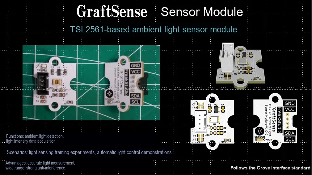
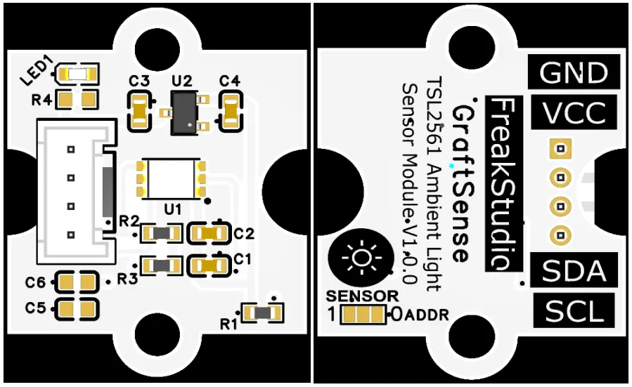
Ambient light sensor module based on TSL2561, which adopts the TSL2561 digital light sensor solution, integrates dual-channel detection of visible light and infrared light, and can realize wide-range ambient light intensity measurement; the module is equipped with an address selection circuit, a LDO voltage regulator circuit, power filtering and indicator circuit, powered by 3.3V and communicates with the main control through the I²C interface, supports multiple gain and integration time configurations, and is suitable for scenarios such as screen automatic dimming, smart home, and Internet of Things devices.
II. Introduction to Main Chips
TSL2561 is a high-precision digital ambient light sensor integrated with dual-channel photoelectric detection, which can sense visible light and infrared light. It features a wide measurement range, strong anti-interference capability, and supports I2C communication, making it suitable for automatic backlight brightness adjustment and light detection in smart devices.
2.1 Chip Overview
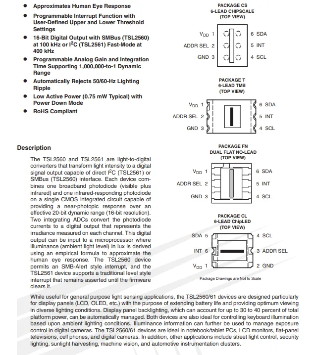
TSL2561 is an optical-to-digital converter featuring dual-channel photodetection (visible light + infrared, pure infrared), outputting 16-bit digital signals, supporting I²C / SMBus communication, and capable of calculating illuminance values approximating human eye response. It supports programmable gain and integration time, with a maximum dynamic range of 1000000:1, can suppress 50/60Hz lamp flicker, and is equipped with programmable interrupt function and low-power mode. It is suitable for scenarios such as backlight adjustment of display devices, keyboard lighting control, and exposure control of digital cameras, and is available in multiple package forms.
2.2 Pin Definition
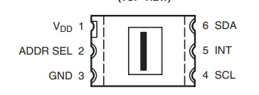
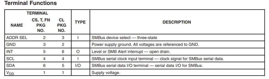
TSL2561 has 6 pins with the following functions: Pin 1 VDD for power supply, Pin 3 GND for ground; Pin 2 ADDR SEL for I²C address selection (tri-state); Pin 4 SCL and Pin 6 SDA serve as the I²C clock/data interface; Pin 5 INT is an open-drain output interrupt pin, which can be used for light threshold triggering.
2.3 Functional Block Diagram
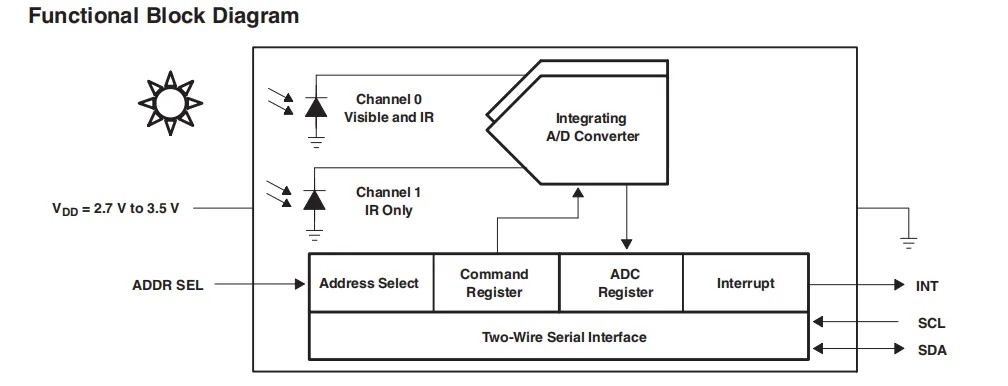
TSL2561 When the sensor is operating, its dual-channel photodiodes separately collect optical signals of visible light + infrared and pure infrared, which are converted into digital signals via an integrating ADC and then stored in registers. It communicates with the host through the I²C interface, and its address selection pins can configure the bus address. When the light intensity exceeds the set threshold, the chip triggers a signal via the interrupt pin, realizing light monitoring and automatic response.
2.4 Performance Parameters
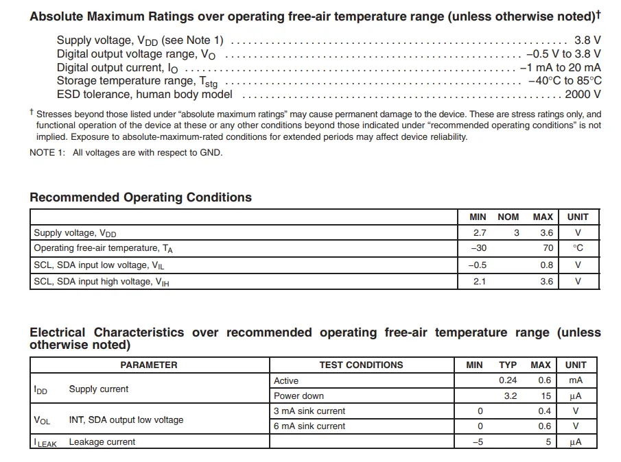
TSL2561 has a recommended power supply voltage range of 2.7~3.6V (maximum 3.8V), an operating temperature range of -30~70℃, a typical operating current of 0.24mA, and a typical current of 3.2μA in power-down mode; it also provides key parameters including I²C interface level, output low voltage and leakage current, and exceeding the absolute maximum ratings will result in device damage.
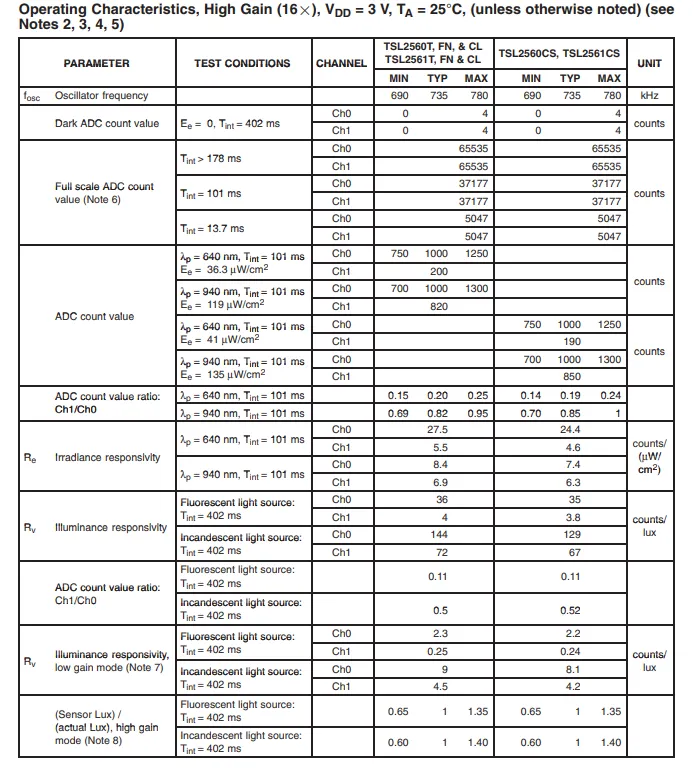
TSL2561 specifies the optoelectronic performance parameters under the conditions of high gain (16×), 3V power supply and 25℃, including oscillator frequency, dark current and full-scale ADC counts under different integration times, as well as key indicators such as channel ADC counts, count ratio, irradiance/illuminance responsivity and measurement error ratio under different wavelengths and light source conditions, which are used to characterize the response characteristics of the sensor to different optical environments.
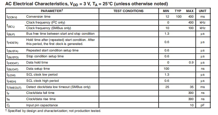
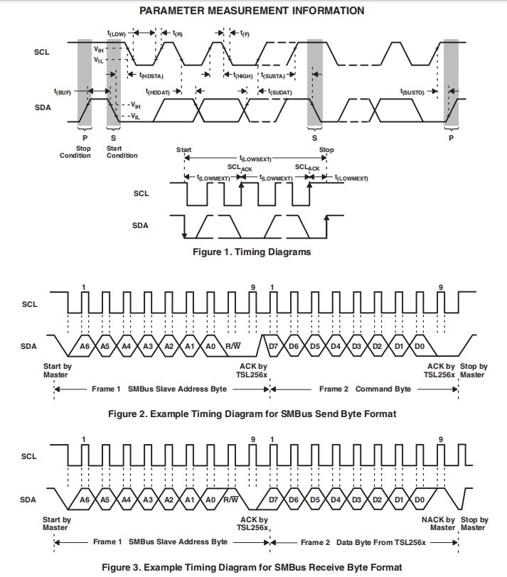
TSL2561 defines the key timing parameters for I²C / SMBus communication in its AC electrical characteristics under 3V supply and 25°C: the ADC conversion time ranges from 12ms to 400ms, the maximum I²C clock frequency is 400kHz, the maximum SMBus clock frequency is 100kHz, along with parameters including bus setup/hold time, high/low level period, rise/fall time, and input capacitance, which provide a design basis for reliable timing of bus communication.
2.5 Reference Circuit
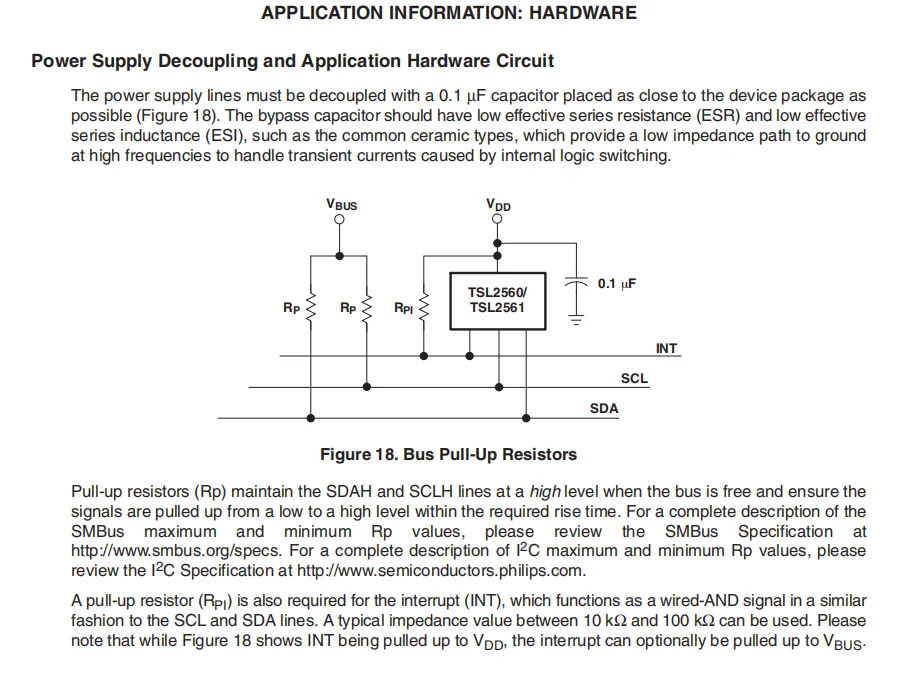
TSL2561 's power supply pin is decoupled locally via a 0.1μF low- ESR ceramic capacitor to filter out high-frequency noise;I²C bus (SCL / SDA) and open-drain interrupt pin (INT) both require pull-up resistors (Rp for SCL / SDA, RPI for INT) to maintain a high level when the bus is idle and ensure the signal rising edge meets timing requirements; the pull-up resistor for INT typically ranges from 10kΩ to 100kΩ, and can be connected to either VDD or the bus power supply.
2.6 Chip Configuration
None.
2.7 Communication Interfaces and Related Protocols
2.7.1 I2C Communication
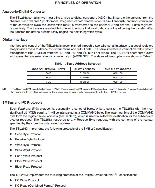
The TSL2561 chip has two built-in integrating ADCs that simultaneously collect the currents of the dual-channel photodiodes and convert them into digital signals, with the data stored in registers via double buffering; control and data reading are implemented through a two-wire serial interface compatible with SMBus and I²C, the address is determined by the level of the ADDR SEL pin, communication specifies the register address via a command byte with the most significant bit set to 1, and supports multiple SMBus and I²C protocols for read and write operations.
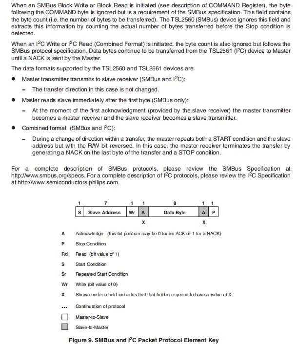
TSL2560 ignores the byte count field in SMBus block transfers and determines the transfer length by detecting the stop condition;TSL2561 continues transferring in accordance with the I²C standard until the host sends a NACK; it also defines three data transfer directions: host write, host read, and combined format, as well as the meanings of protocol element symbols (start/stop bits, address, read/write bit, acknowledge bit).
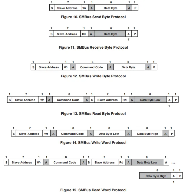
TSL2561 supports the SMBus communication timing sequence, and demonstrates the frame structures of six protocols: byte transmission, byte reception, single-byte write/read, and word write/read, which include start/stop bits, slave address, read/write bit, command code, data bytes and acknowledge bits, among which read operations usually require a repeated start bit to switch the direction.
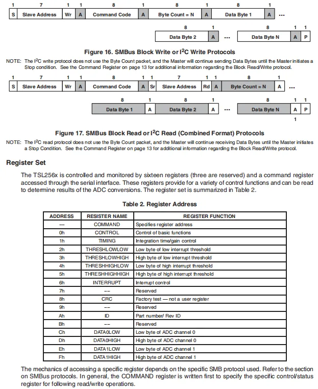
TSL2561 features the SMBus block read/write and I²C read/write protocol frame structures: in block transfers, the SMBus includes a byte count field, while I²C terminates transfers via a master stop condition; the chip integrates 16 registers (including 3 reserved bits) covering functions such as control, timing, interrupt thresholds, device ID, and dual-channel ADC data, and all read/write operations require the target address to be specified first via the COMMAND register.
2.7.2 Registers
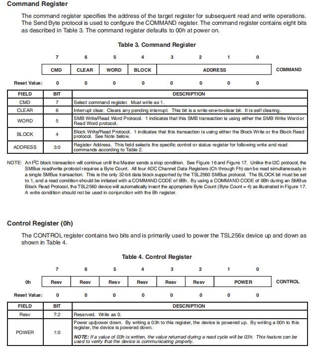
TSL2561 's COMMAND register (power-on default: 00h) is used to specify the target address for subsequent read and write operations; its highest bit CMD must be set to 1, and it also supports interrupt clearing and word/block transfer mode configuration. The CONTROL register (0h) only has the lower two bits POWER valid: writing 0x03 powers on the device, writing 0x00 powers it down, and reading returns 0x03 to verify the communication status.
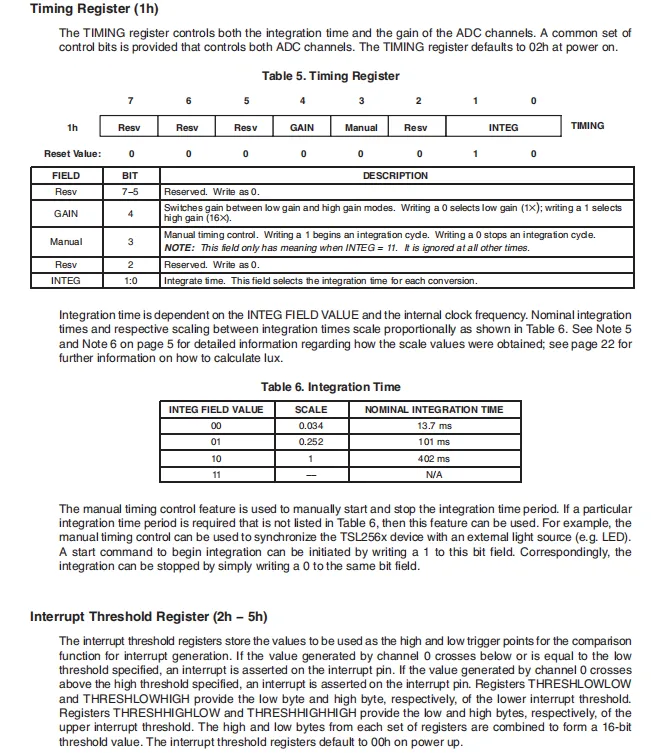
TSL2561 's TIMING register (1h, default value 02h) controls the integration time and gain of the ADC; the INTEG bits configure three integration periods of 13.7ms, 101ms and 402ms (corresponding to different scaling factors), the GAIN bit switches between 1× low gain and 16× high gain, and the Manual bit supports manually starting and stopping integration to achieve external synchronization.Interrupt threshold registers (2h – 5h) * are used to set the 16-bit high and low thresholds; an interrupt is triggered when the ADC value of channel 0 exceeds this range, with a default power-on value of 00h.
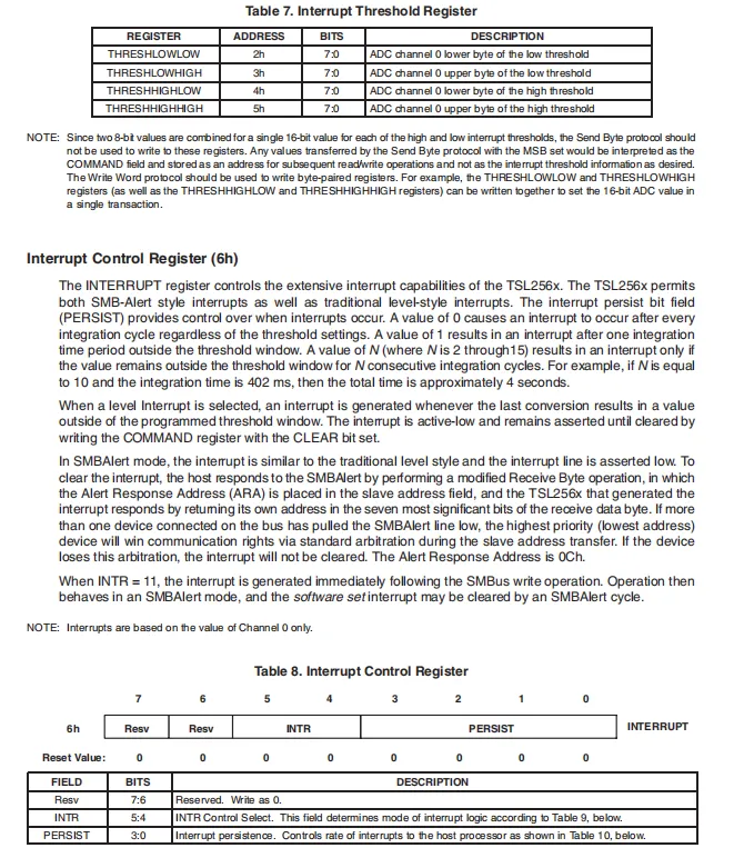
TSL2561 interrupt threshold registers (2h – 5h) are used to set the 16-bit high and low trigger thresholds for Channel 0, which must be configured in pairs via the word-write protocol; the interrupt control register (6h) selects the interrupt mode (level / INTR) via the SMBAlert bit, the PERSIST bit sets the number of consecutive threshold-exceeding cycles required to trigger an interrupt, the interrupt is controlled by Channel 0 data, in level mode it must be cleared via the COMMAND register's CLEAR bit, while in SMBAlert mode it is cleared by the host via arbitration response.
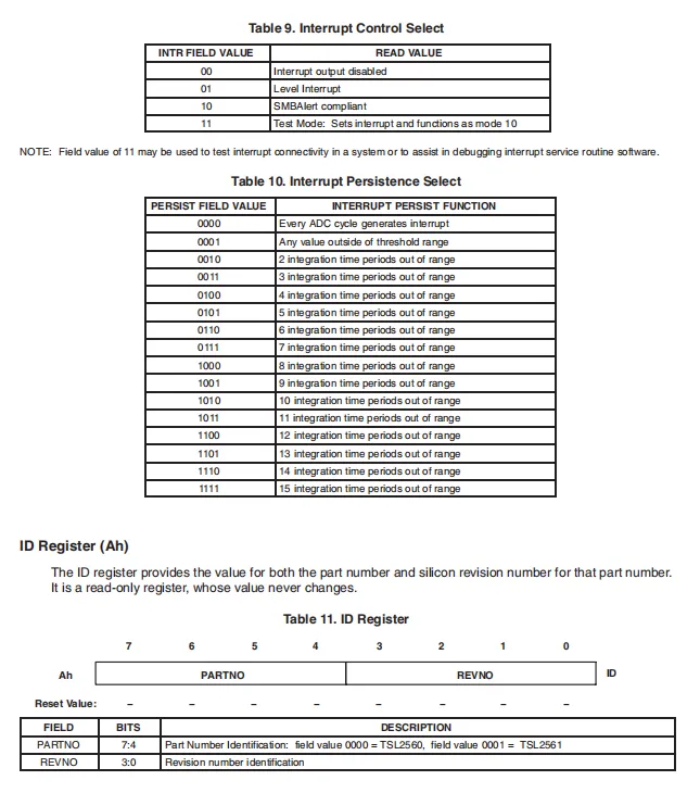
TSL2561 interrupt control register's INTR bits can disable interrupts, select level / SMBAlert mode, or enter test mode;PERSIST bits set the number of consecutive ADC cycles (1-15) that the value must exceed the threshold before triggering an interrupt; the read-only ID register (Ah) is used to identify the chip model and revision, with the upper 4 bits distinguishing TSL2560 / TSL2561 and the lower 4 bits being the silicon revision number.
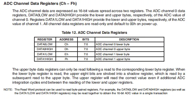
TSL2561 dual-channel 16-bit light intensity data is stored in the high and low byte registers of DATA0 / DATA1 respectively. All registers are read-only and default to 00h upon power-up. When reading, the low byte must be read first followed by the high byte; after the low byte is read, the high byte will be latched into the shadow register to avoid errors caused by data update during the reading process. Alternatively, the complete 16-bit data can be read in one go via the read word protocol.
2.8 PCB Routing Precautions
None.
III. Circuit Engineering
3.1 Circuit Source Engineering
To obtain the circuit source project, please follow the official account [Freak Embedded]
3.2 Module Usage Instructions
The schematic diagram of this module is shown below:
SCH_Schematic1_TSL2561-Based Ambient Light Sensor Module_v1.0.0_2026-05-11.pdf 2.4 MB
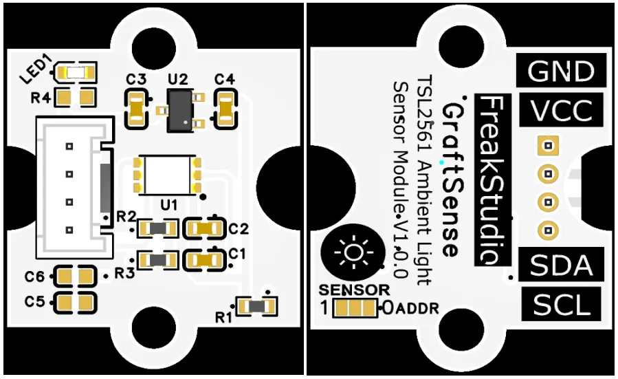
This module provides an IIC communication interface: it supports standard I2C communication rates, allows flexible configuration of the ADDR pin to set the I2C address, is compatible with 3.3V logic levels, and can stably transmit the dual-channel ambient light intensity digital signals collected by the TSL2561, making it suitable for scenarios such as automatic screen dimming, smart homes, and IoT devices, and providing the system with reliable wide-range data interaction capability for ambient light sensing.
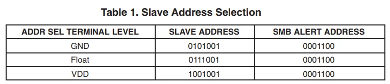
ADDR The specific address selection is as follows:
3.3 Application Experiment
Here, we use the GraftPort-RP2040 development board for testing, and the TSL2561-based ambient light sensor module communicates with the main controller via the I2C interface.
Here, we first use the HY2.0-4P cable to connect the module to the GraftPort-RP2040 development board's I2C0 interface:
development board pins | Module Pins | Description |
Pin 4 |
|
|
Pin 5 |
|
|
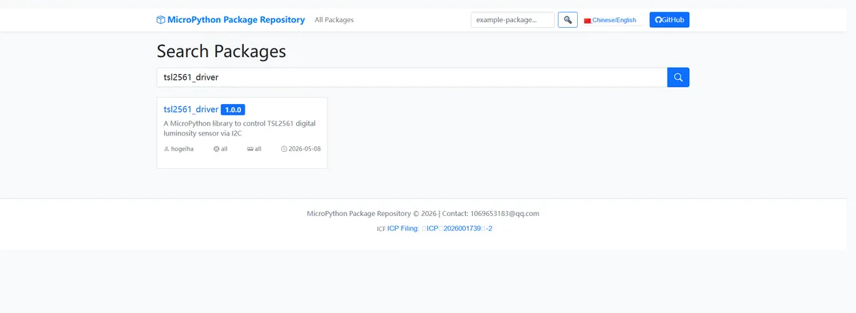
Here, we need to search for the relevant driver packages on uPyPI: https://upypi.net/zh/
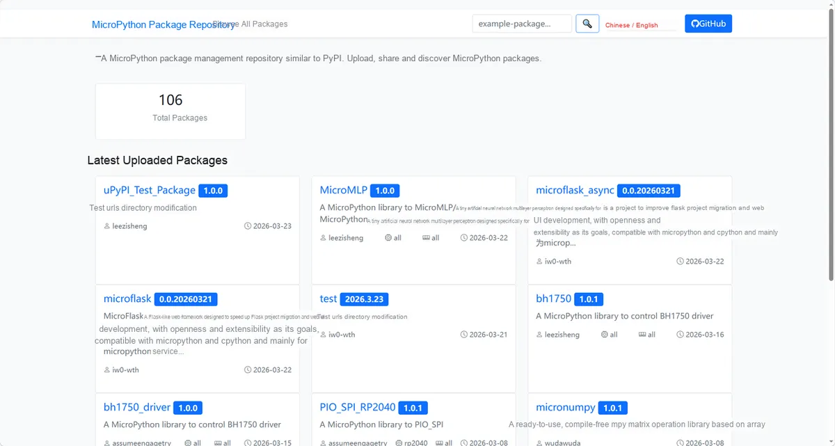
Enter tsl2561_driver to search, and the following will be displayed:
Click to copy the local installation command:
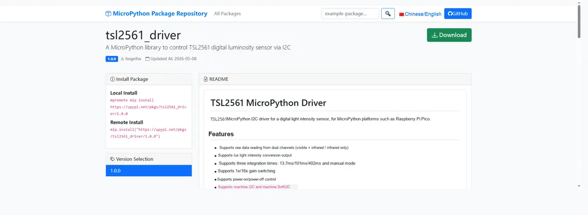
Import the module driver library code via the mip tool. Below are the usage commands for the mpremote tool:
mpremote mip install https://upypi.net/pkgs/tsl2561_driver/1.0.0Import the ambient light sensor module based on TSL2561 - MicroPython driver code, then copy the following main.py code into our project:
# Python env   : MicroPython v1.23.0
# -*- coding: utf-8 -*-
# @Time    : 2026/4/21 PM
# @Author  : hogeiha
# @File    : main.py
# @Description : TSL2561 digital light intensity sensor reading example

# ======================================== Import Modules =========================================

from machine import Pin, SoftI2C
from tsl2561 import TSL2561, T_SLOW
import time

# ======================================== Global Variables ============================================

# List of common TSL2561 I2C addresses
TARGET_SENSOR_ADDRS = [0x29, 0x39, 0x49]

# I2C data line connected to Pico GPIO4
I2C_SDA_PIN = 4

# I2C clock line connected to Pico GPIO5
I2C_SCL_PIN = 5

# Set I2C communication frequency to 100kHz
I2C_FREQ = 100000

# ======================================== Functions ============================================

# ======================================== Custom Classes ============================================

# ======================================== Initialization configuration ===========================================

time.sleep(3)
print("FreakStudio: TSL2561 lux sensor")

# Initialize software I2C bus
i2c_bus = SoftI2C(sda=Pin(I2C_SDA_PIN), scl=Pin(I2C_SCL_PIN), freq=I2C_FREQ)

# Scan I2C bus devices
devices_list = i2c_bus.scan()
print("START I2C SCANNER")

# Check whether any I2C device was found
if len(devices_list) == 0:
    print("No i2c device")
    raise SystemExit("I2C scan found no devices")

# Print the number of scanned I2C devices
print("I2C devices found:", len(devices_list))

# Placeholder for the sensor object
sensor = None

# Iterate through all scanned I2C addresses
for device in devices_list:
    # Check whether the current address is a common TSL2561 address
    if device in TARGET_SENSOR_ADDRS:
        print("I2C hexadecimal address:", hex(device))

        try:
            # Create TSL2561 sensor object
            sensor = TSL2561(i2c_bus, addr=device)

            # Set 402ms integration time and 1x gain
            sensor.set_timing_gain(T_SLOW, gain=False)

            # Read and print sensor ID
            sensor_id = sensor.get_id()
            print("Sensor initialization successful")
            print("TSL2561 ID:", sensor_id)
            break
        except Exception as e:
            print("Sensor initialization failed:", e)
            continue

# Exit the program when the target sensor is not found
if sensor is None:
    raise SystemExit("No TSL2561 device found")

# Wait for the first integration to complete
time.sleep(0.5)

# ========================================  Main Program  ============================================

try:
    while True:
        # Read raw dual-channel light data
        raw_channel_0, raw_channel_1 = sensor.read_raw()

        # Read converted light intensity
        lux = sensor.get_lumi()

        # Print light data in English format
        print(
            "CH0: {}  CH1: {}  Lux: {:.2f}".format(
                raw_channel_0,
                raw_channel_1,
                lux,
            )
        )

        # Read the sensor once per second
        time.sleep(1)
except KeyboardInterrupt:
    # Turn off the sensor on interrupt to reduce power consumption
    sensor.set_power_up(False)

    # Print the stop message
    print("Measurement stopped")
Burn the code, open the terminal, and the output is as follows:
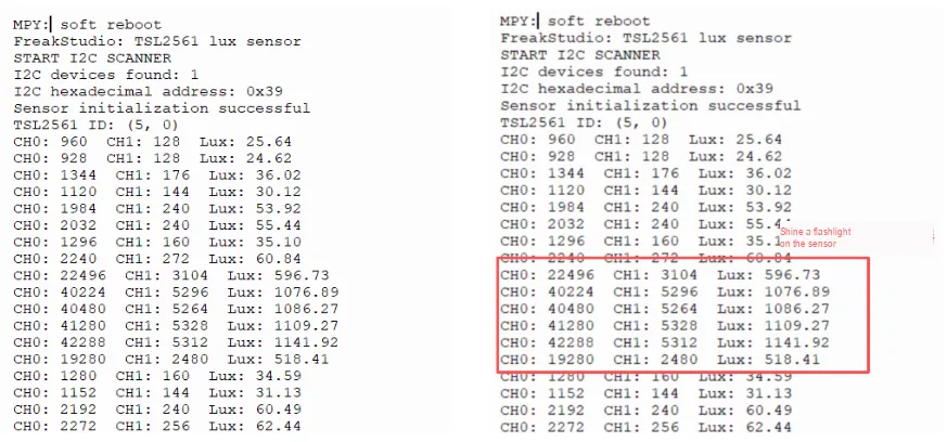
The TSL2561 light sensor functions properly in I2C communication and initialization, stably outputs dual-channel data and illuminance (lux) values that fluctuate in real time with changes in ambient light, exhibits normal range response under strong light, and is in good working condition.
IV. Drivers
5. BOM & Recommended Alternative Parts
None.
VI. Revision History
Document Version | Date of Revision | Modifier | Modify Content |
v1.0 | 2026-05-11 | Zero High-Luck | Initialize the document |
v1.1 | 2026-06-06 | Xin Ruili | Create an open version of the document based on the internal document version v1.0. |
VII. Relevant Materials
7.1 Chip Datasheet
TSL2561.pdf 343 KB
7.2 Unique Icons for PCB Silk Screen