Contents
- I. Module Introduction
- II. Introduction to Main Chips
- 2.1 Chip Overview
- 2.2 Pin Definition
- 2.3 Functional Block Diagram
- 2.4 Performance Parameters
- 2.5 Reference Circuit
- 2.6 Chip Configuration
- 2.7 Communication Interfaces and Related Protocols
- 2.8 PCB Routing Precautions
- III. Circuit Engineering
- 3.1 Circuit Source Engineering
- 3.2 Module Usage Instructions
- 3.3 Application Experiment
- IV. Drivers
- 5. BOM & Recommended Alternative Parts
- VI. Revision History
- 7. Relevant Materials
- 7.1 Chip Datasheet
- 7.2 Unique Icons for PCB Silk Screen
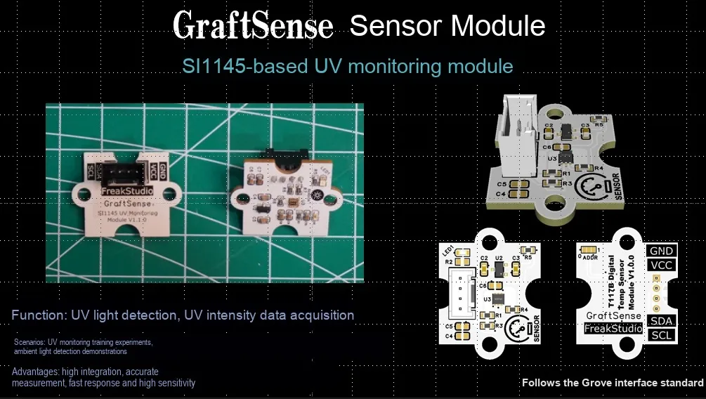
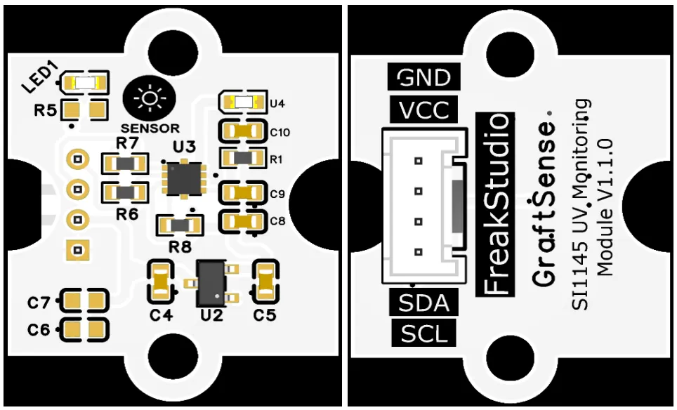
I. Module Introduction
UV monitoring module based on SI1145, which adopts the Silicon Labs SI1145 3-in-1 optical sensor solution, integrates infrared LED, optical shielding and signal processing circuits, and can simultaneously realize UV index detection, ambient light detection and proximity detection within 1cm~50cm; the module is equipped with LDO voltage regulator circuit, power filtering and indicator circuit, powered by 3.3V and communicates with the main controller via the I²C interface, supports autonomous periodic measurement and interrupt triggering, and is suitable for scenarios such as wearable devices, smart homes, screen dimming, and gesture sensing.
II. Introduction to Main Chips
SI1145 is Silicon Labs 's low-power, highly integrated optical sensor chip that can simultaneously detect ambient light, ultraviolet index, and infrared proximity and output digital signals via the I²C interface.
2.1 Chip Overview
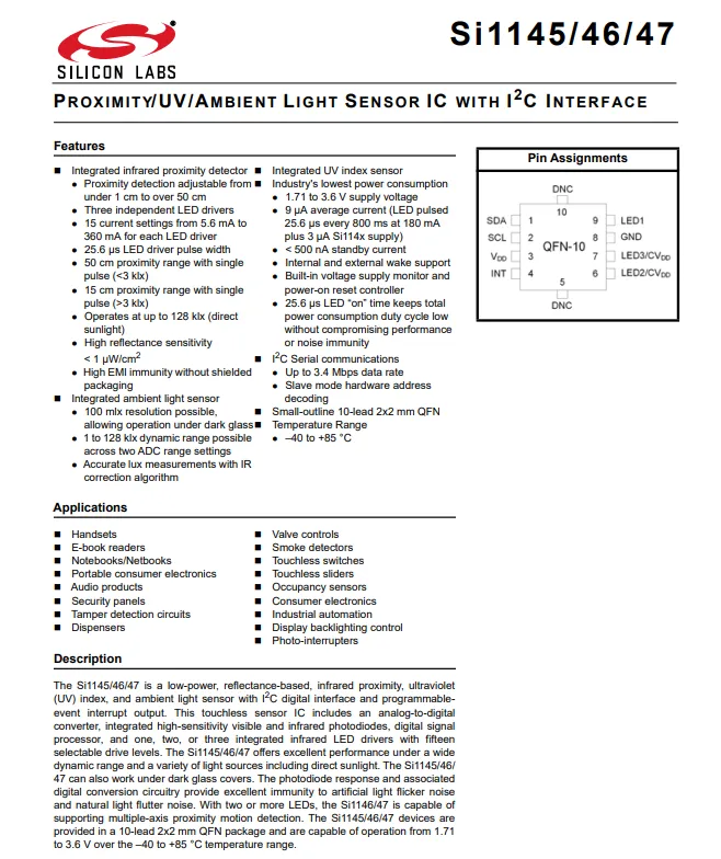
SI1145 is a Silicon Labs launched low-power integrated optical sensor chip, which adopts the QFN-10 package, and realizes synchronous detection of infrared proximity (with a detection distance up to 50cm), UV index and ambient light through the I²C interface. It features high sensitivity, low power consumption (with an average current of only 9μA), EMI interference resistance and other characteristics, supports operation in a wide temperature range of -40~85℃, and is widely used in consumer electronics, smart home, industrial automation and other scenarios.
2.2 Pin Definition
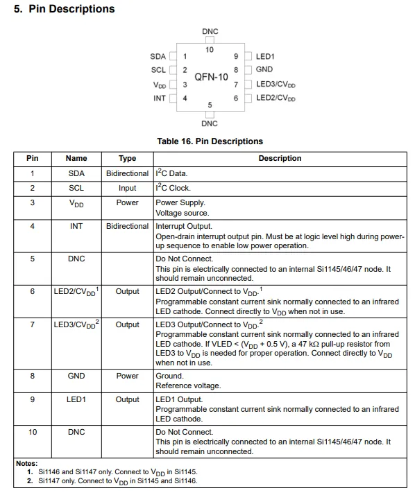
SI1145 adopts the QFN-10 package with clearly defined core pin functions: Pin 1 is SDA, Pin 2 is SCL — these two pins serve as the I²C communication interface; Pin 3 is VDD for power supply; Pin 4 is INT as open-drain interrupt output; Pin 8 is GND for ground connection; Pins 6/7/9 (LED2 / CVDD, LED3 / CVDD, LED1) are programmable constant-current sink outputs, used to drive infrared LED s for proximity detection, and can be directly connected to VDD when unused; Pins 5 and 10 are no-connect pins that require floating treatment.
2.3 Functional Block Diagram
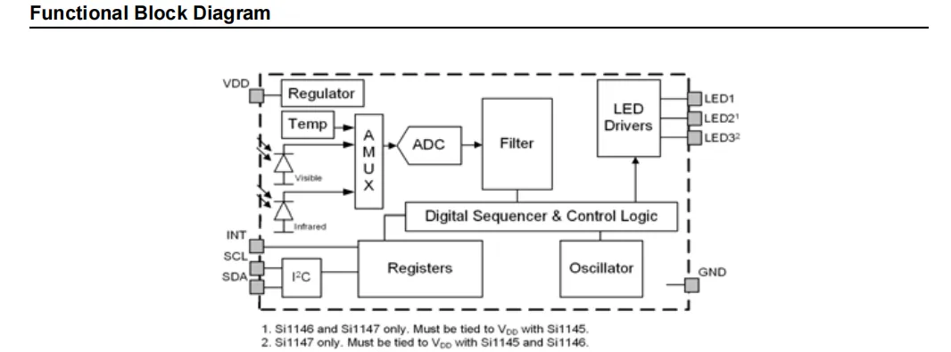
The SI1145 chip uses its on-chip visible light and infrared photodiodes to collect ambient light, ultraviolet and reflection signals, which are sent through a multiplexer to an ADC for conversion. After digital filtering, the signals are processed by the control logic: on one hand, it drives the LED driver to output infrared LED signals to achieve proximity detection; on the other hand, it stores the data in registers and communicates with the main controller via the I²C interface. It also supports interrupt output and power management, enabling multi-parameter optical sensing at low power consumption.
2.4 Performance Parameters
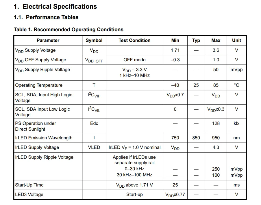
SI1145 has a supply voltage of 1.71-3.6V and an operating temperature range of -40 to 85°C. For the I²C interface, the high and low level thresholds are 0.7 VDD and 0.3 VDD respectively; the infrared LED has a typical emission wavelength of 850nm, a maximum supply voltage of 4.3V, can withstand a maximum illuminance of 128klx under direct sunlight, and the device start-up time is no less than 25ms, which provides key parameter basis for design and application.
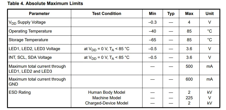
SI1145 absolute maximum operating conditions: supply voltage VDD range - 0.3~4V, operating temperature - 40~85℃, storage temperature - 65~85℃;LED pins and I/O pins have a maximum voltage rating of 3.6V, the total LED current is up to 500mA, and the ground current is up to 600mA;ESD protection level: 2kV for both human body model and charged device model, 225V for machine model. Exceeding these parameters will cause permanent damage to the device.
2.5 Reference Circuit
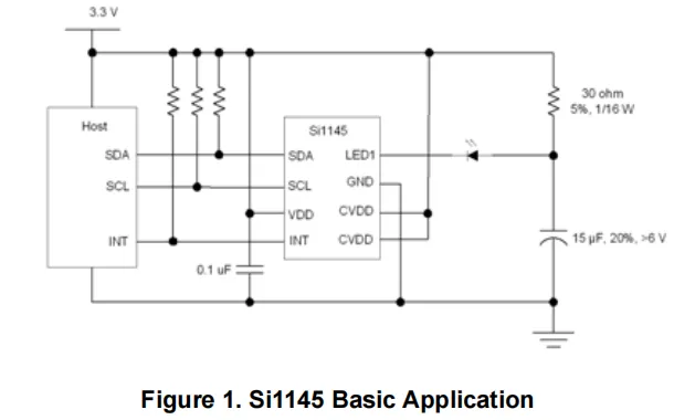
3.3V power supply powers the chip;VDD pin is accompanied by a 0.1μF capacitor for power filtering;SDA and SCL implement I²C communication via pull-up resistors;INT pin is directly connected to the host to output interrupt signals;LED1 pin drives an infrared LED through a 30Ω current-limiting resistor, and cooperates with a 15μF capacitor to filter out ripples, realizing the infrared emission function required for proximity detection. The chip receives the reflected signal through a built-in photodiode, and finally outputs ambient light, ultraviolet index and proximity detection data to the host via the I²C interface.
2.6 Chip Configuration
None.
2.7 Communication Interfaces and Related Protocols
2.7.1 IIC Communication
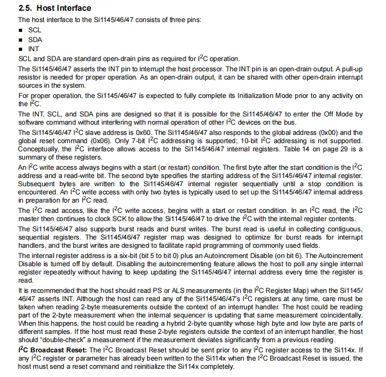
SI1145 has three pins on its host interface, including SCL, SDA and INT. Among them, SCL / SDA are standard I²C open-drain pins, and INT is an open-drain interrupt output requiring an external pull-up resistor;The chip I²C slave address is 0x60, which supports 7-bit addressing, burst read/write and automatic address increment. A write operation starts with a start condition + device address + register address; for a read operation, the address must be sent first before data is read. It also supports a global reset command, and the master can obtain measurement data via interrupt or direct reading, while attention should be paid to the consistency issue of double-byte measurement reading.
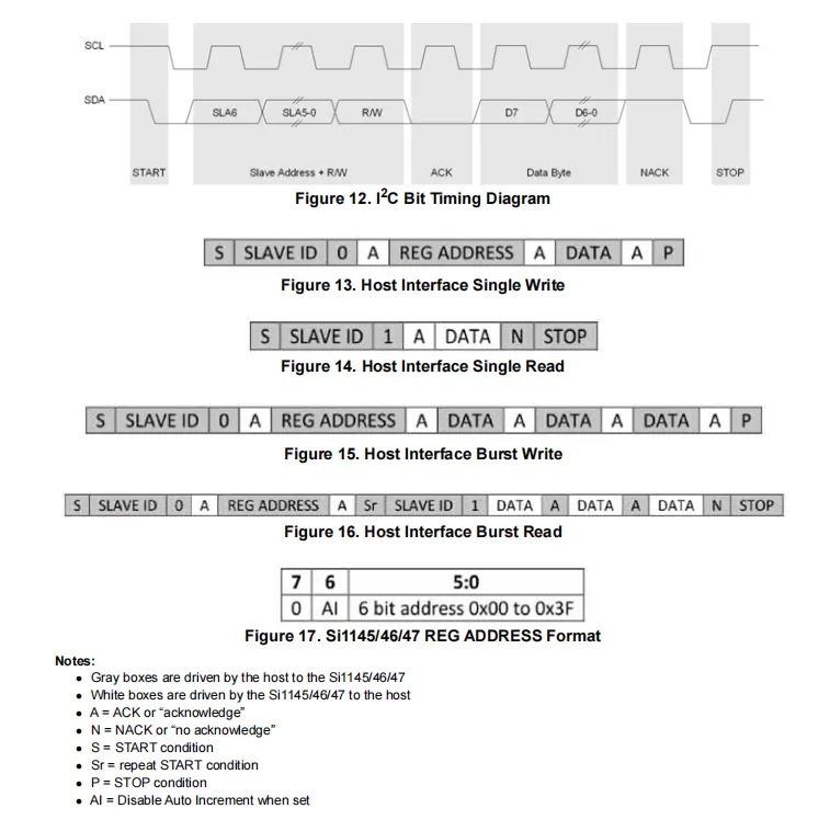
SI1145 I²C Communication Timing and Operation Format: It covers the complete procedures of standard bit timing, single-byte read/write, and burst read/write. The register address is 6 bits (0x00 – 0x3F), and supports turning off automatic address increment via the AI bit. Communication follows the standard I²C protocol consisting of start, address + R/W, acknowledge, data transmission, and stop. The host and the chip respectively drive the corresponding signals and confirm the transmission status via ACK / NACK.
2.7.2 Registers
2.7.2.1 Register Programming Guide
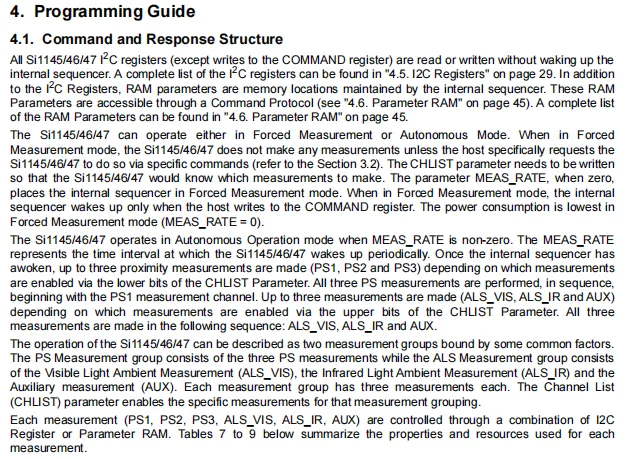
SI1145 chip supports forced measurement and autonomous operation two operating modes: In forced mode, measurement is only triggered when the host writes to the command register, delivering the lowest power consumption; in autonomous mode, the chip wakes up at the cycle set by the non-zero MEAS_RATE parameter, completes proximity and ambient light measurement in the channel order configured by the CHLIST parameter, and measurement data can be accessed via I²C registers or the parameter RAM, enabling flexible power consumption and measurement control.
2.7.2.2 Register Resource Allocation
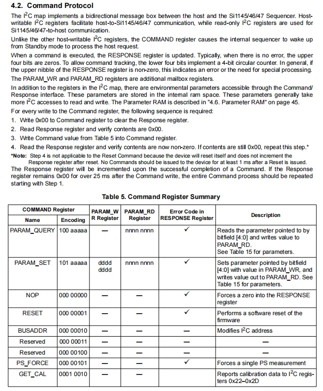
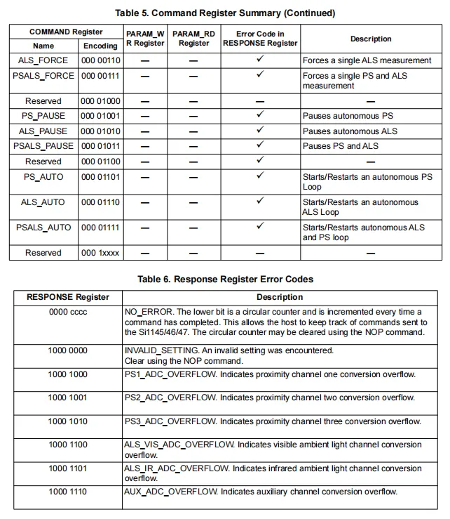
SI1145 Command Protocol and Status Feedback Mechanism: The host sends commands via the COMMAND register to implement functions including single forced measurement (ALS / PS / PSALS_FORCE), pausing or starting the autonomous measurement loop (PS / ALS / PSALS_PAUSE / AUTO), parameter read/write (PARAM_QUERY / SET), and software reset.After execution, RESPONSE register will update its status: the lower 4 bits serve as a loop counter, and the upper 4 bits act as an error code, which can feed back faults such as invalid settings and ADC overflow of each channel. The host needs to interact in the fixed sequence of "clear response → verify → send command → read status" to ensure the reliability of communication and measurement.
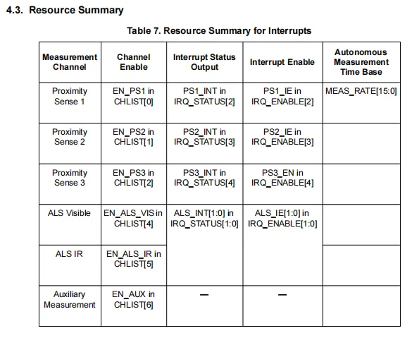
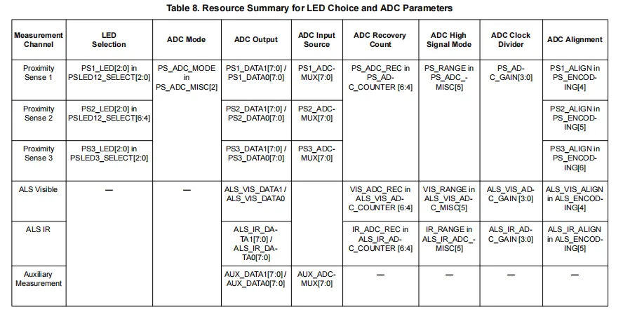
SI1145 configures the measurement channel resources, and defines the interrupt control and ADC parameter mapping for proximity detection (PS1 / 2 / 3), ambient light (ALS visible light / infrared) and auxiliary measurement channels: the corresponding channels can be enabled via the CHLIST register, and the interrupt status and enable are configured in the IRQ_STATUS and IRQ_ENABLE registers;Meanwhile, parameters of each channel including LED selection, ADC mode, output register, recovery count, signal range, clock frequency division and data alignment are all configured via specific registers to achieve precise control over different measurement channels.
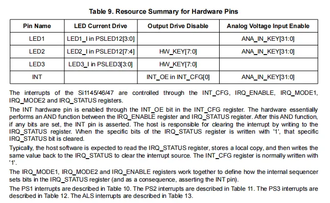
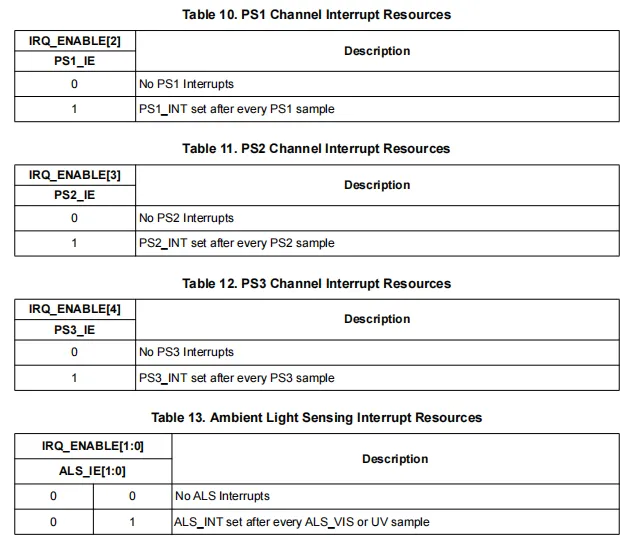
SI1145 ’s LED1 / 2 / 3 pins' drive current, output control and analog input functions can be configured via corresponding registers;the INT pin is enabled by the INT_CFG register, and interrupt management is implemented through registers such as IRQ_ENABLE and IRQ_STATUS;The interrupts of the PS1 / 2 / 3 and ALS channels can be independently enabled via the IRQ_ENABLE register, which triggers an INT signal after each measurement is completed. The host needs to clear the interrupt flag by reading from and writing to the IRQ_STATUS register to achieve efficient measurement status feedback.
2.7.2.3 I2C Communication Registers
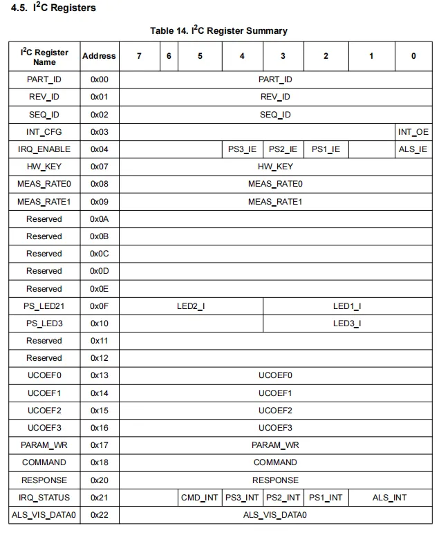
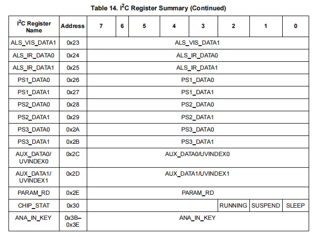
SI1145 I²C register map covers all functions including chip identification, interrupt control, measurement configuration, data reading and status management: registers such as PART_ID / REV_ID identify chip information, the INT_CFG / IRQ series registers control interrupts, MEAS_RATE sets the measurement period, PS_LEDxx configures infrared LED current, UCOEF stores ultraviolet calibration parameters, COMMAND / RESPONSE implements command interaction, the ALS / PS / AUX_DATA series registers store visible light, infrared, proximity and auxiliary measurement data, and CHIP_STAT reflects the chip's operating status; the host can read from and write to these registers via I²C to complete chip configuration, control and data reading.
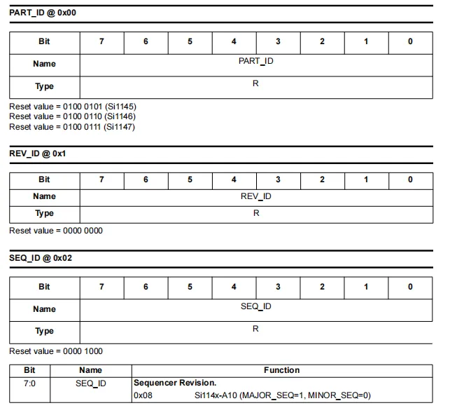
SI1145 has three read-only identification registers: PART_ID (0x00), REV_ID (0x01) and SEQ_ID (0x02). PART_ID has different reset values to distinguish specific models (SI1145 is 0x45, SI1146 is 0x46, SI1147 is 0x47);REV_ID is fixed at 0x00, representing the chip revision;SEQ_ID The reset value is 0x08, which identifies the internal sequencer version (e. g., A10 version). The host can identify the chip model and version information by reading these registers.
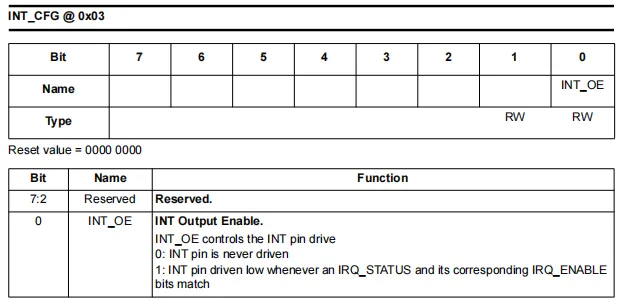
SI1145 's INT_CFG register (address 0x03) is used to configure the output enable of the interrupt pin INT: only bit0 (INT_OE) of this register is valid, with a reset value of 0, and the remaining bits are reserved. When INT_OE = 0, the INT pin is never driven; when INT_OE = 1, as long as the IRQ_STATUS bits match the corresponding IRQ_ENABLE bits, the INT pin will be pulled low to send an interrupt signal to the host.
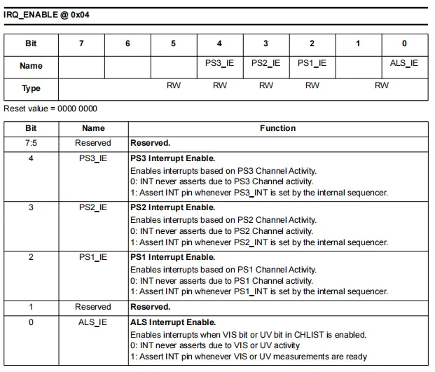
SI1145 IRQ_ENABLE register (address 0x04) is used to enable the interrupts of each measurement channel: this register is readable and writable with a reset value of 0, in which bit4 to 2 are the interrupt enable bits for the PS3, PS2, and PS1 channels respectively, bit0 is the interrupt enable bit for the ALS (visible light / infrared / ultraviolet) channel, and bit7 to 5 as well as bit1 are reserved bits.When the corresponding bit is set to 1, as long as the measurement of the corresponding channel is completed and the IRQ_STATUS register is set, the INT pin will be pulled low to trigger an interrupt; when set to 0, the interrupt trigger of this channel is masked.
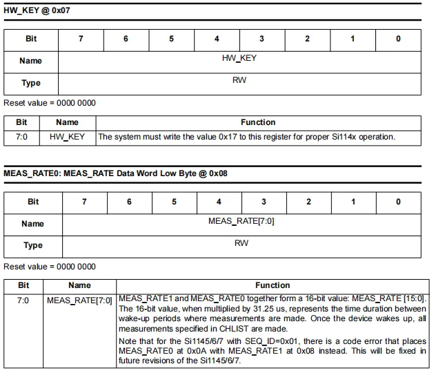
Two key registers of the SI1145: HW_KEY (0x07) and MEAS_RATE0 (0x08).
HW_KEY Register (Address 0x07): To ensure normal operation of the chip, the host must write 0x17 to this register; otherwise, the device will fail to enter normal operating state.
MEAS_RATE0 Register (Address 0x08): It, together with MEAS_RATE1 (0x09), forms a 16-bit MEAS_RATE value, which is used to set the wake-up period in automatic measurement mode with a unit of 31.25μs. When this value is 0, the chip operates in forced measurement mode; when it is non-zero, the chip will automatically wake up at the set period and complete all measurements specified by the CHLIST register.
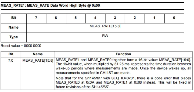
MEAS_RATE1 register (address 0x09), which together with MEAS_RATE0 (0x08) forms a 16-bit MEAS_RATE value, serving as the upper 8 bits to store period configuration data. When this value is multiplied by 31.25μs, the result is the wake-up interval in automatic measurement mode, and the device will perform all measurements specified by CHLIST according to this period. In addition, the document also notes that some older versions of the chip have an errata issue regarding the address of this register.
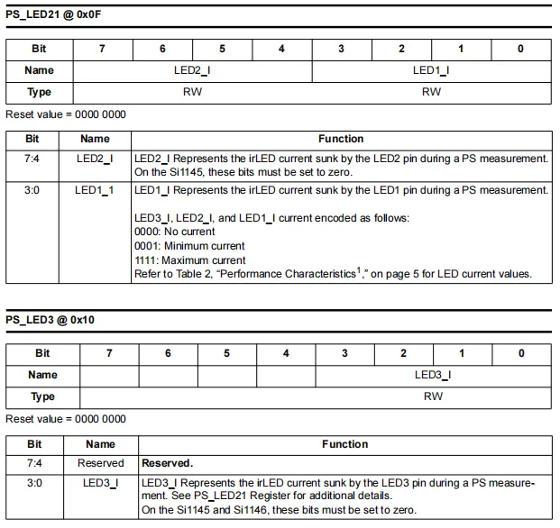
SI1145 has two infrared LED current configuration registers:
PS_LED21 (Address 0x0F): The upper 4 bits LED2_I control the drive current of the LED2 pin, which must be set to 0 on the SI1145; the lower 4 bits LED1_I control the current of the LED1 pin, with the code ranging from 0000 (no current) to 1111 (maximum current).
PS_LED3 (Address 0x10): Only the lower 4 bits of LED3_I are valid, which control the drive current of the LED3 pin. The encoding rule is consistent with the above, and this bit must be set to 0 on the SI1145.
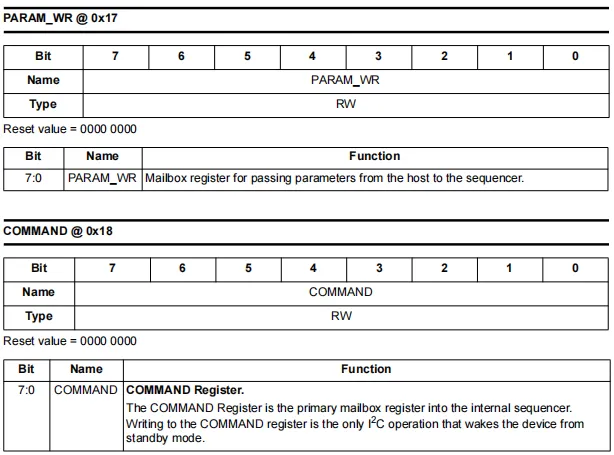
The two interaction registers of SI1145:
PARAM_WR(Address0x17): serves as a "mailbox" for the host to transmit configuration parameters to the internal sequencer, and is used to write parameter values in coordination with command operations.COMMAND(Address0x18): The core command register of the chip, serving as the primary channel for interaction between the host and the internal sequencer. Writing to this register is the onlyI²Coperation that can wake the chip from standby mode; by writing different command codes, functions such as software reset, forced measurement, and parameter read/write can be implemented.
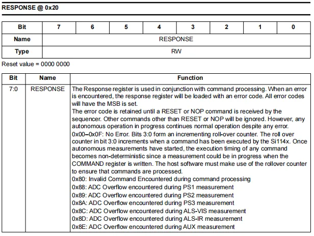
SI1145 's RESPONSE register (address 0x20), which serves as the status feedback register for command processing: its upper 4 bits act as an error code (when the MSB is set to 1, it indicates an error), and its lower 4 bits function as a loop counter when no error occurs. When there is no error (the value ranges from 0x00 to 0x0F), the lower 4 bits increment as commands are executed;When an error occurs, a specific error code will be written (e. g., 0x80 for invalid command, 0x88 ~ 0x8E for ADC overflow of each channel). The error code will remain until a RESET or NOP command is received, and the host can read this register to determine the command execution result and device status.
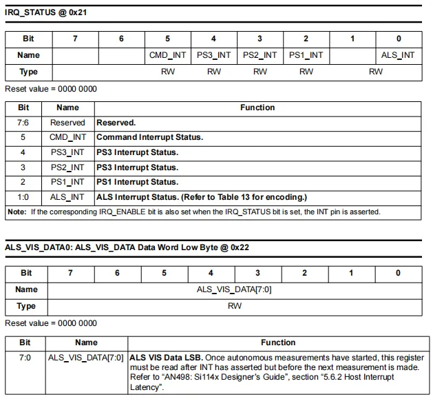
IRQ_STATUS (Address 0x21): Interrupt status register, which records the measurement completion status of each channel. bit5 is the command interrupt flag, bit4 ~ 2 are the interrupt flags for the PS3, PS2, and PS1 channels respectively, and bit0 is the interrupt flag for the ALS channel. When the corresponding bit and the corresponding bit in the IRQ_ENABLE register are both set to 1, the INT pin will be pulled low to trigger an interrupt, and the host can clear the corresponding flag by writing a 1 to it.
ALS_VIS_DATA0 (Address 0x22): Low-byte register for visible light ambient light measurement data, which forms a 16-bit measurement result together with ALS_VIS_DATA1 (0x23). In automatic measurement mode, this register must be read after the INT pin is triggered and before the next measurement starts to prevent data from being overwritten.
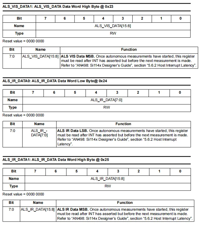
ALS_VIS_DATA1 (Address 0x23): The upper 8 bits (MSB) of the visible light ambient light measurement data, which forms a complete 16-bit measurement result together with ALS_VIS_DATA0 (0x22).
ALS_IR_DATA0 (Address 0x24): Lower 8 bits (LSB) of the infrared ambient light measurement data.
ALS_IR_DATA1 (address 0x25): the upper 8 bits (MSB) of the infrared ambient light measurement data, which forms a complete 16-bit measurement result together with ALS_IR_DATA0.
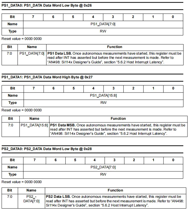
PS1_DATA0(0x26) andPS1_DATA1(0x27): respectively represent the lower 8 bits (PS1channel measurement data, i. e.,LSB) and the upper 8 bits (MSB), which together form a 16-bit result.PS2_DATA0(0x28):PS2channel measurement data lower 8 bits, which form a complete result together with the subsequentPS2_DATA1register.
PS1_DATA0, PS1_DATA1 and PS2_DATA0 registers are all read/write with a reset value of 0. In automatic measurement mode, the host must read the data after the INT pin triggers an interrupt and before the next measurement starts to avoid being overwritten by new results. For the reading method, please refer to the chapter on host interrupt latency in "AN498: Si114x Designer's Guide".
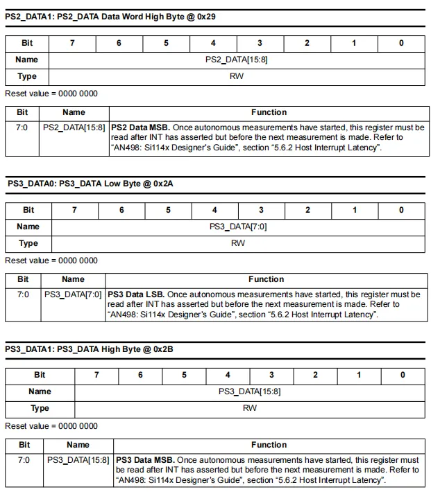
PS2_DATA1(0x29): The high 8 bits of the measurement data of the PS2 channel (MSB), which forms a 16-bit result together withPS2_DATA0(0x28).PS3_DATA0(0x2A): Lower 8 bits of the measurement data of the PS3 channel (LSB).PS3_DATA1(0x2B): the upper 8 bits of the measurement data for the PS3 channel (MSB), which forms a complete 16-bit result together withPS3_DATA0.
PS2_DATA1, PS3_DATA0 and PS3_DATA1 registers are all read-write with a reset value of 0. In automatic measurement mode, the host must read the data after the interrupt is triggered by the INT pin and before the next measurement to prevent the result from being overwritten. For specific operations, please refer to the interrupt latency section in "AN498: Si114x Designer's Guide".
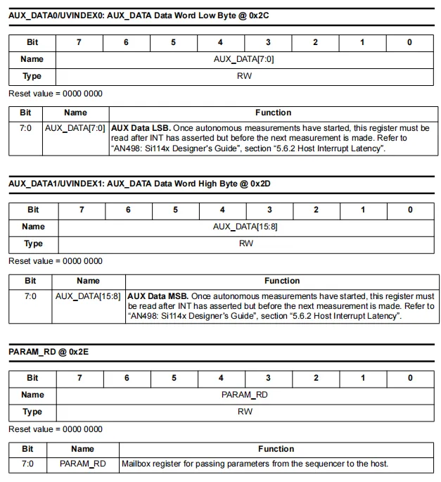
AUX_DATA0/UVINDEX0 (0x2C) and AUX_DATA1/UVINDEX1 (0x2D): correspond to the lower 8 bits and upper 8 bits of the auxiliary measurement (ultraviolet index) data respectively, forming a 16-bit result. In automatic measurement mode, these registers must be read after an INT trigger and before the next measurement to prevent the data from being overwritten.
PARAM_RD (0x2E): A "mailbox" register for the host to read parameters from the internal sequencer, used in conjunction with the PARAM_QUERY command to obtain configuration parameter values.
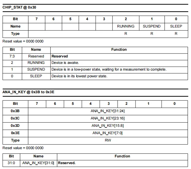
CHIP_STAT (Address 0x30): A read-only chip status register that reflects the current operating mode of the device.
RUNNING(bit2): When set to 1, it indicates that the chip is in the wake-up working state.SUSPEND(bit 1): When set to 1, it indicates that the chip is in a low-power suspend state and waiting for the measurement to complete.SLEEP(bit 0): When set to 1, it indicates that the chip is in the sleep state with the lowest power consumption.
ANA_IN_KEY (Address 0x3B-0x3E): Read-write register, consisting of 4 bytes to form 32-bit data; it is reserved for future use and requires no user operation.
2.7.2.4 RAM Register
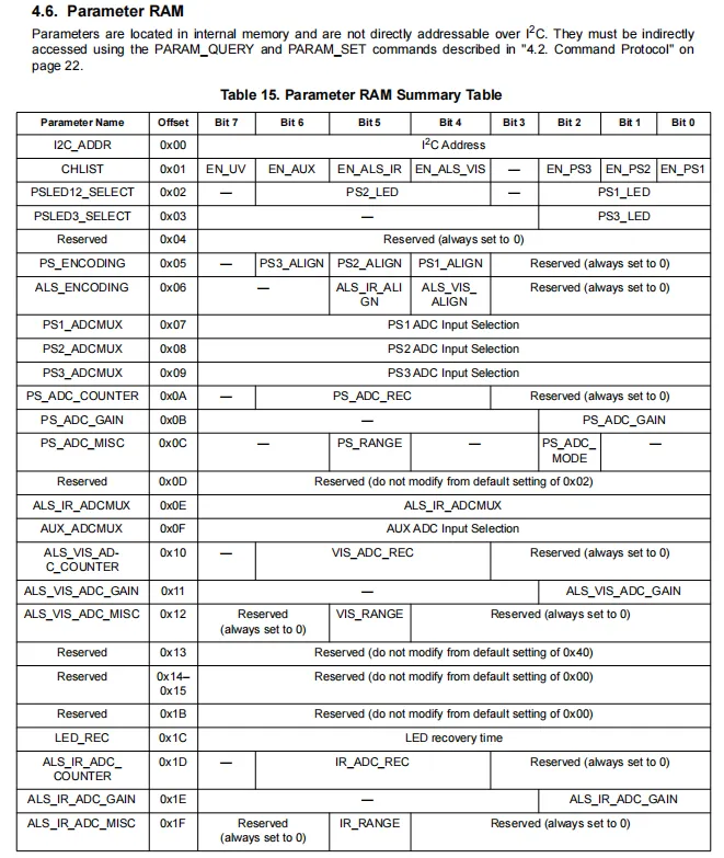
The parameter RAM (Parameter RAM) configuration table of the SI1145 is used to store internal chip parameters that cannot be directly accessed via I²C, and indirect read and write operations on these parameters need to be performed via the PARAM_QUERY and PARAM_SET commands.
- Measurement Channel Enable /
CHLISTregister (offset 0x01) controls the enabling of channels includingPS1/2/3,ALSvisible light/infrared, and ultraviolet. LEDandADCConfiguration:PSLEDxx_SELECTselects the infraredLEDfor proximity detection;PS/ALS_ENCODINGsets data alignment;PS/ALS_ADCMUXconfiguresADCinput channels;ADC_COUNTER/GAIN/MISCcontrolsADCrecovery count, gain and measurement mode.- Other key parameters: including
I²Caddress setting,LEDrecovery time, etc. Some parameters are reserved items and shall be kept at their default values; users only need to modify specific configuration bits.
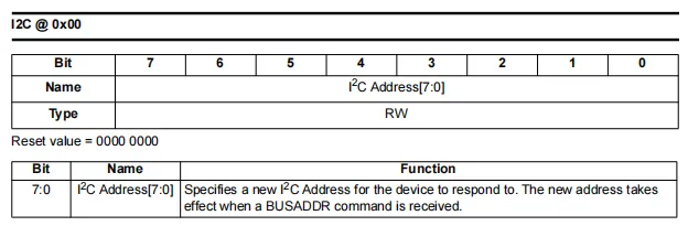
SI1145 I2C address configuration parameter (offset 0x00) is a read-write RAM configuration item with a reset value of 0x00.
Bit7:0(I²CAddress[7:0]): Used to set a newI²Cslave address for the chip. The written address value does not take effect immediately; the chip will only switch to the new address to respond to subsequent communications after the host sends theBUSADDRcommand, which can be used to resolve address conflicts on theI²Cbus.
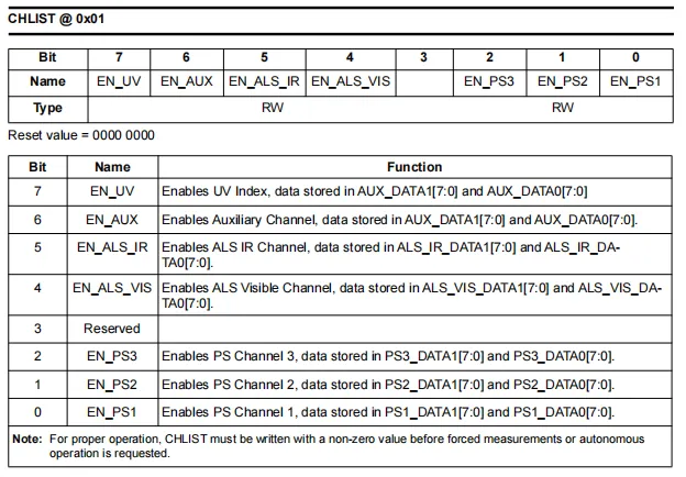
SI1145 's CHLIST parameter (offset 0x01) is used to configure the enable of measurement channels. Its reset value is 0, and it must be set to a non-zero value to perform forced or automatic measurement.
Bit7(EN_UV): Enables the ultraviolet index measurement, and the data is stored inAUX_DATA0/1.Bit6(EN_AUX): Enables auxiliary channel measurement, and the data is also stored inAUX_DATA0/1.Bit5(EN_ALS_IR): Enables infrared ambient light measurement, with the data stored inALS_IR_DATA0/1.Bit4(EN_ALS_VIS): Enables visible light ambient light measurement, with the data stored inALS_VIS_DATA0/1.Bit3: Reserved bit, must be set to 0.Bit2-0(EN_PS3/PS2/PS1): Enables the 3 proximity detection channels respectively, with the data stored sequentially inPS3/PS2/PS1_DATA0/1.
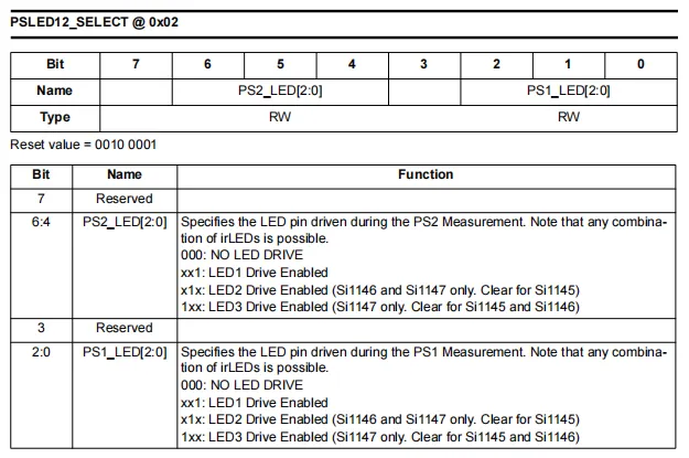
SI1145 's PSLED12_SELECT parameter (offset 0x02) has a reset value of 0010 0001 (i. e. 0x21), which is used to configure the infrared PS1 and PS2 channel LED driver pins during proximity detection.
Bit7,Bit3: reserved bits, which must be kept at 0.Bit6-4(PS2_LED[2:0]): Specify thePS2measurement-drivenLEDpin.000: Do not drive anyLED.xx1: drivesLED1.x1x: DrivesLED2(supported only onSi1146/1147; must be set to 0 forSi1145).1xx: DriveLED3(only supported bySi1147;Si1145/1146should be set to 0).
Bit2-0(PS1_LED[2:0]): Specifies theLEDpins to be driven duringPS1measurement. The encoding rule is the same as above; theSi1145only supports drivingLED1.
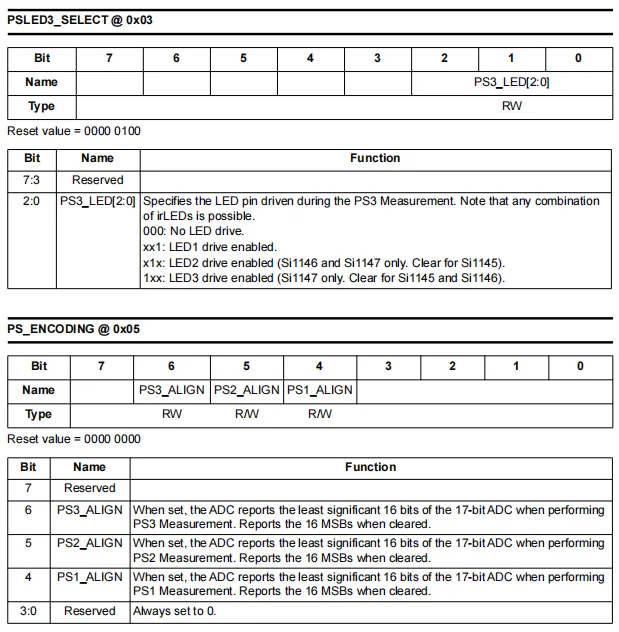
PSLED3_SELECT(offset0x03, reset value0x04)- Bits [2:0]
PS3_LEDare used to configure the infraredLEDpin driven during PS3 channel proximity detection, with the encoding rule consistent with that ofPSLED12_SELECT:000: No driving of anyLEDxx1: DriveLED1x1x: DriveLED2(only supported bySi1146/1147, set to 0 forSi1145)1xx: DriveLED3(only supported bySi1147;Si1145/1146should be set to 0)
- The upper 5 bits are reserved bits and shall be set to 0.
- Bits [2:0]
PS_ENCODING(Offset0x05, Reset Value0x00)- Used to configure the data alignment mode of the three proximity detection channels for
ADC, and truncate the 17-bitADCresult to 16-bit output:PS3_ALIGN(bit 6),PS2_ALIGN(bit 5),PS1_ALIGN(bit 4): When set to 1, the lower 16 bits of the 17-bit data are taken; when set to 0, the upper 16 bits are taken.
- The remaining bits are reserved bits and shall be set to 0.
- Used to configure the data alignment mode of the three proximity detection channels for
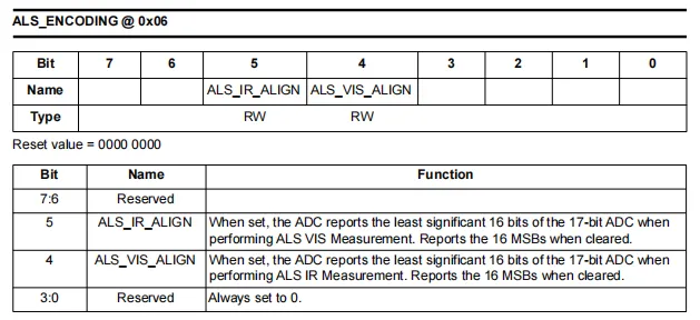
SI1145 ALS_ENCODING parameter (offset 0x06, reset value 0x00) is used to configure the data alignment mode of the ambient light channel ADC.
Bit7-6,Bit3-0: Reserved bits, must always be set to 0.Bit5(ALS_IR_ALIGN): Controls the 17-bitADCresult truncation mode of the ambient infrared light (ALS IR) channel. When set to 1, the lower 16 bits of data are output; when set to 0, the upper 16 bits of data are output.Bit4(ALS_VIS_ALIGN) : Controls the 17-bitADCresult interception method of the visible ambient light (ALS VIS) channel. When set to 1, outputs low 16-bit data; when set to 0, outputs high 16-bit data.
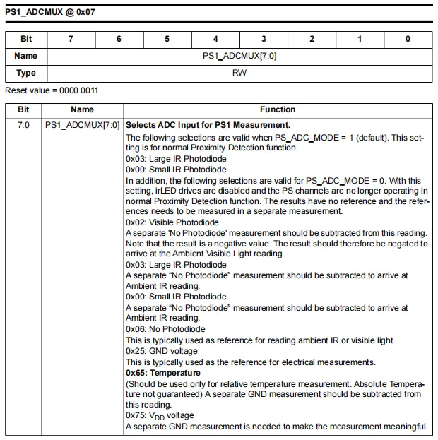
SI1145 's PS1_ADCMUX parameter (offset: 0x07, reset value: 0x03) is used to configure the ADC input source selection for the PS1 channel.
- This parameter is a readable and writable 8-bit register, used to specify
PS1the input channel ofADCduring measurement, and supports multiple measurement modes:- Default mode (
PS_ADC_MODE= 1, proximity detection):0x03: Select a large-sized infrared photodiode (Large IR Photodiode, default)0x00: Select a small-sized infrared photodiode (Small IR Photodiode)
- Extended mode (
PS_ADC_MODE= 0, non-standard proximity detection):0x02: Visible light photodiode (differential processing is required in conjunction with the "photodiode-free" measurement)0x06: No photodiode (used as the reference standard for ambient light measurement)0x25: Ground voltage (GND, used as a reference for electrical measurements)0x65: Temperature sensor (only for relative temperature measurement, theGNDreading shall be subtracted)0x75: Power supply voltage (VDD, the reading ofGNDshall be subtracted)
- Default mode (
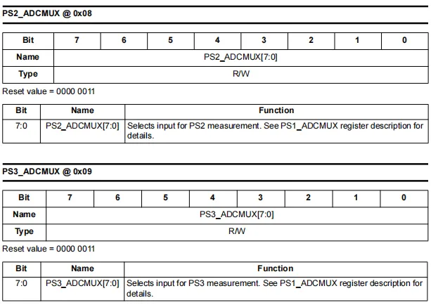
SI1145 's PS2_ADCMUX (offset 0x08 ) and PS3_ADCMUX (offset 0x09 ) parameters are both readable and writable 8-bit registers with reset values of 0000 0011 (i.e. 0x03 ). ADC input source selection for configuring PS2 and PS3 channels , respectively:
- Default value
0x03indicates selecting a large-sized infrared photodiode for standard proximity detection. - Other supported configurations (such as small-sized infrared tubes, visible light photodiodes, temperature sensors, power supply voltage, etc.) are the same as those of
PS1_ADCMUX, and reference can be made to the description of this register.
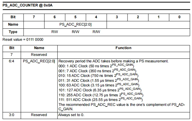
SI1145 's PS_ADC_COUNTER parameters (offset 0x0A , reset value 0x70 ) are used to configure the recovery period of the proximity detection ( PS ) channel ADC .
Bit7: Reserved bit, must be set to 0.Bit6-4(PS_ADC_REC [2:0]) : Set the recovery period of theADCbefore performingPSmeasurement, in units ofADCclocks. Period =2 ^ (n + 1) - 1clock, each clock cycle is50 ns × 2 ^ PS_ADC_GAIN. The reset value0111corresponds to the longest recovery period (511 clocks).Bit3-0: Reserved bit, must always be set to 0.- It is recommended to set
PS_ADC_RECtothe complement of PS_ADC_GAINto optimize the measurement timing and noise performance.
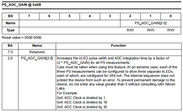
SI1145 PS_ADC_GAIN parameter (offset: 0x0B, reset value: 0x00) is used to configure the PS (proximity detection) channel's ADC gain.
Bit7-3: Reserved bits, must be set to 0.Bit2-0(PS_ADC_GAIN[2:0]): Controls the infraredLEDpulse width andADCintegration time of the PS channel. A larger value corresponds to a longer time (amplified by a factor of2^PS_ADC_GAIN), resulting in higher measurement sensitivity but a corresponding increase in power consumption.- For example:
0x0corresponds to 1x clock,0x4corresponds to 16x clock,0x5corresponds to 32x clock.
- For example:
- To prevent permanent damage to the device, do not set this value higher than 5; otherwise, damage may be caused by excessive
LEDdrive current.
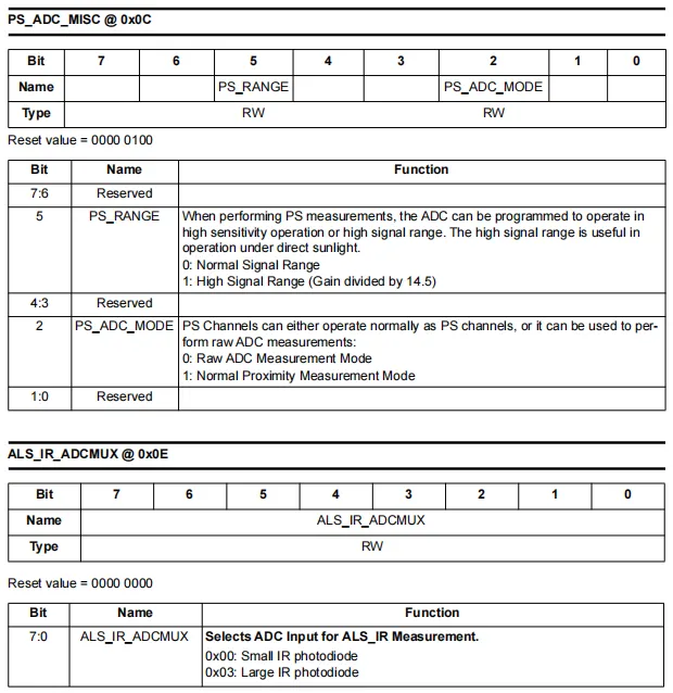
PS_ADC_MISC (offset 0x0C, reset value 0x04)
Bit7-6,Bit4-3,Bit1-0: Reserved bits, must be set to 0.Bit5(PS_RANGE): Configures the measurement range of thePSchannel'sADC. 0 corresponds to normal mode (high sensitivity); 1 corresponds to high signal range mode (gain divided by 14.5, suitable for scenarios with direct strong light exposure).- Bit2 (
PS_ADC_MODE): Configure the operating mode of thePSchannel. 0 indicates the originalADCmeasurement mode (noLEDdriving, available for other measurements);1indicates the normal proximity detection mode (default).
ALS_IR_ADCMUX (Offset: 0x0E, Reset Value: 0x00)
- An 8-bit read-write register used to configure the input source of the
ALS_IRchannel for infrared ambient lightADC. 0x00: Select a small-sized infrared photodiode (default value).0x03: Select a large-sized infrared photodiode.- This channel can only be configured with an infrared photodiode and cannot be set to any other mode.
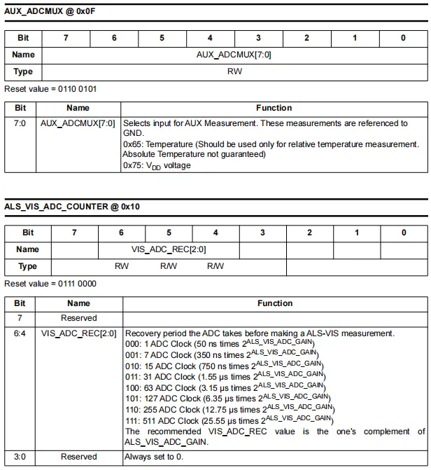
AUX_ADCMUX (offset 0x0F, reset value 0x65)
- An 8-bit read-write register used to configure the
AUXchannel'sADCinput source, with measurement results referenced toGND. 0x65: Temperature sensor (default value, only used for relative temperature measurement, absolute temperature accuracy cannot be guaranteed).0x75: Power supply voltage (VDD) measurement.
ALS_VIS_ADC_COUNTER (Offset: 0x10, Reset Value: 0x70)
Bit7,Bit3–0: Reserved bits, must be set to 0.Bit6-4(VIS_ADC_REC[2:0]): Set theADCrecovery period before visible light ambient light (ALS-VIS) measurement, in units ofADCclock cycles.- Period =
(2^(n+ 1) - 1) × 50 ns × 2^ALS_VIS_ADC_GAIN - Reset value
111corresponds to the maximum recovery period (511 clock cycles).
- Period =
- It is recommended to set
VIS_ADC_RECtothe complement of ALS_VIS_ADC_GAINto optimize the measurement timing and noise performance.
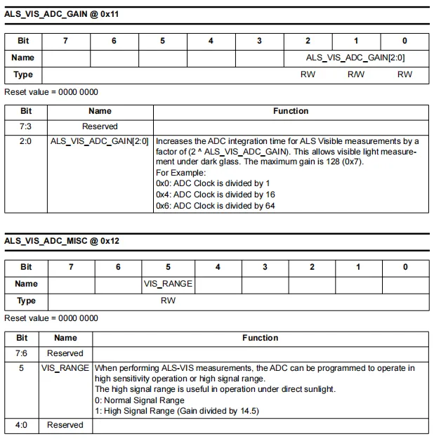
ALS_VIS_ADC_GAIN (offset 0x11, reset value 0x00)
- Bits [2:0]
ALS_VIS_ADC_GAIN[2:0]are used to set the integration time of theADCfor visible light measurement, with amplification by a factor of2^N(whereNis the set value), so as to improve the measurement sensitivity in low-light environments; the maximum gain can reach 128x (0x7). - For example:
0x0corresponds to 1x clock,0x4corresponds to 16x,0x6corresponds to 64x. - The upper 5 bits are reserved bits and shall be set to 0.
ALS_VIS_ADC_MISC (Offset: 0x12, Reset Value: 0x00)
- Only Bit5 (
VIS_RANGE) is valid, which is used to configure the measurement range of the visible light channel:0: Normal signal range, high-sensitivity mode (default).1: High signal range mode, with the gain divided by 14.5, which can prevent signal saturation under direct strong light (such as sunlight).
- The remaining bits are reserved bits and shall be set to 0.
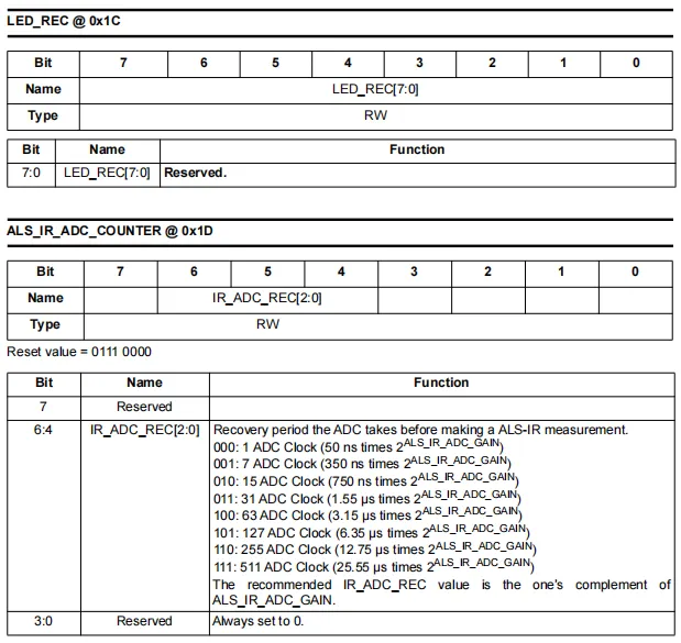
LED_REC (offset 0x1C)
- It is an 8-bit read-write register. All bits are reserved bits with no actual functional definition, and the default settings shall be maintained.
ALS_IR_ADC_COUNTER (Offset: 0x1D, Reset Value: 0111 0000)
- Configure the
ADCrecovery period for infrared ambient light (ALS-IR) measurements. Bit7,Bit3-0: Reserved bits, must be set to 0.Bit6-4(IR_ADC_REC[2:0]): Set the recovery period, in units ofADCclock cycles. The period =(2^(n+ 1) - 1) × 50 ns × 2^ALS_IR_ADC_GAIN. The reset value111corresponds to the maximum recovery period (511 clock cycles).- It is recommended to set
IR_ADC_RECto the complement ofALS_IR_ADC_GAINto optimize the measurement timing and noise performance.
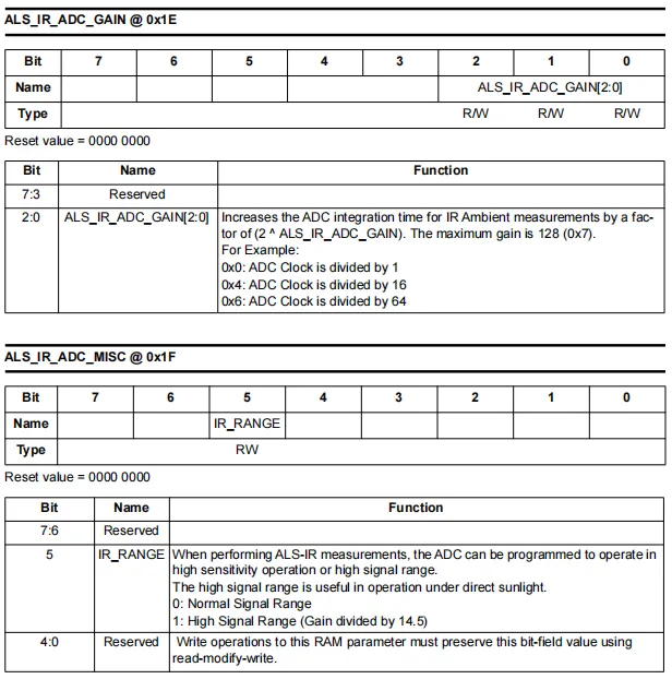
ALS_IR_ADC_GAIN (offset 0x1E, reset value 0x00)
- the lower 3 bits
ALS_IR_ADC_GAIN[2:0], which are used to set the integration time of theADCfor infrared ambient light measurement; the value is amplified by a factor of2^N(whereNis the set value), with a maximum gain of up to 128x (0x7), so as to improve the measurement sensitivity in low-light environments. - For example:
0x0corresponds to 1x clock,0x4corresponds to 16x,0x6corresponds to 64x. - The upper 5 bits are reserved bits and shall be set to 0.
ALS_IR_ADC_MISC (Offset 0x1F, Reset Value 0x00)
- Only Bit5 (
IR_RANGE) is valid, which is used to configure the measurement range of the infrared channel:0: Normal signal range, high-sensitivity mode (default).1: High signal range mode, where the gain is divided by 14.5 to avoid signal saturation under direct strong light (such as sunlight).
- The remaining bits are reserved bits and shall be kept at their original values. A "read-modify-write" operation shall be adopted during writing to avoid data corruption.
2.8 PCB Routing Precautions
None.
III. Circuit Engineering
3.1 Circuit Source Engineering
To obtain the source code of the circuit, please follow the official account [Freak Embedded]
3.2 Module Usage Instructions
The schematic diagram of this module is shown below:
SCH_Schematic1_SI1145-based UV monitoring module_v1.0.0_2026-05-11.pdf 2.1 MB
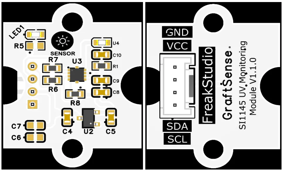
This module provides a IIC communication interface: it supports standard I2C communication rates, is compatible with 3.3V logic levels, and can stably transmit the digital signals of UV index, ambient light intensity and proximity detection collected by SI1145. Suitable for scenarios such as wearable devices, smart homes, screen dimming and gesture sensing, it provides the system with reliable 3-in-1 optical sensing data interaction capability.
3.3 Application Experiment
Here, we use the GraftPort-RP2040 development board for testing, and the SI1145-based ultraviolet monitoring module uses the I2C interface to communicate with the main controller.
Here, we first use the HY2.0-4P cable to connect the module to the GraftPort-RP2040 development board's I2C0 interface:
The module connections are shown in the following table:
Development Board Pins | Module Pins | Description |
Pin 4 |
|
|
Pin 5 |
|
|
Here, we need to search for the relevant driver packages on uPyPI: https://upypi.net/zh/
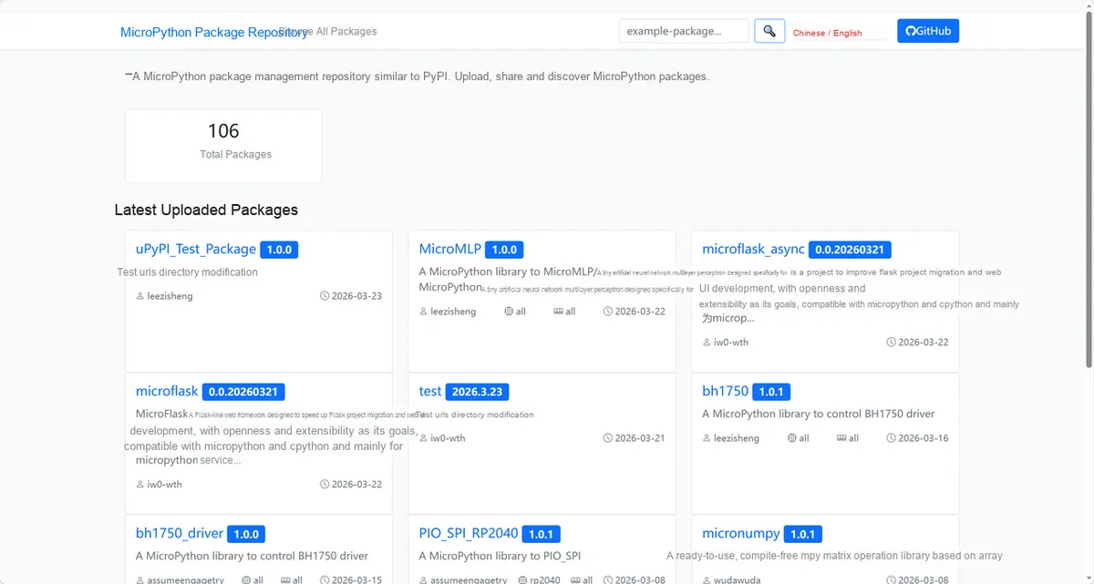
Enter si1145_driver to search, and the following will be displayed:
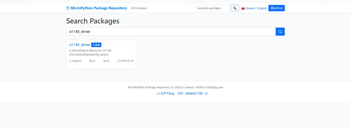
Click to copy the local installation command:
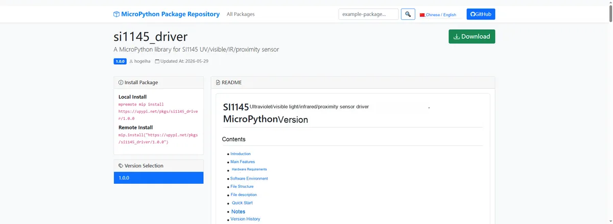
Import the module driver library code via the mip tool. Below are the usage commands for the mpremote tool:
mpremote mip install https://upypi.net/pkgs/si1145_driver/1.0.0Import the UV monitoring module based on SI1145 - MicroPython driver code, then copy the following main.py code into our project:
# Python env   : MicroPython v1.23.0
# -*- coding: utf-8 -*-
# @Time    : 2026/05/06
# @Author  : Nelio Goncalves Godoi
# @File    : main.py
# @Description : Code to test the SI1145 UV/visible light/infrared light/proximity sensor driver class
# @License : MIT

# ======================================== Import Modules =========================================

import time
import micropython
from machine import Pin, SoftI2C
from si1145 import (
    SI1145,
    SI1145_ADDR,
    SI1145_REG_PARTID,
    SI1145_PSALS_PAUSE,
    SI1145_PSALS_AUTO,
    SI1145_PS_FORCE,
    SI1145_ALS_FORCE,
    SI1145_PSALS_FORCE,
    SI1145_RESET,
    SI1145_REG_COMMAND,
)

# ======================================== Global Variables ============================================

# I2C pin and frequency configuration
I2C_SCL_PIN = 5
I2C_SDA_PIN = 4
I2C_FREQ = 100_000

# List of possible I2C addresses for the SI1145 device
TARGET_SENSOR_ADDRS = [0x60, 0x74]

# Device ID register and expected value (SI1145 PART_ID = 0x45)
DEVICE_ID_REG = SI1145_REG_PARTID
DEVICE_ID_EXPECTED = 0x45

# Print interval (ms)
last_print_time = 0
print_interval = 2000

# ======================================== Functions ============================================

def print_realtime_data():
    """Print real-time high-frequency data (high frequency, call commented out by default, can be called manually in the REPL)"""
    # Read the four channels of high-frequency data and print them
    print("UV index: %.2f" % sensor.read_uv)
    print("Visible: %d" % sensor.read_visible)
    print("IR: %d" % sensor.read_ir)
    print("Proximity: %d" % sensor.read_prox)


def switch_to_pause_mode():
    """Switch to paused measurement mode (mode switch, call commented out by default, can be triggered manually in the REPL)"""
    # Write the PSALS_PAUSE command to pause automatic measurement
    sensor._write8(SI1145_REG_COMMAND, SI1145_PSALS_PAUSE)
    print("Sensor switched to PSALS pause mode")


def switch_to_auto_mode():
    """Switch back to automatic continuous measurement mode (mode switch, call commented out by default, can be triggered manually in the REPL)"""
    # Write the PSALS_AUTO command to resume automatic measurement
    sensor._write8(SI1145_REG_COMMAND, SI1145_PSALS_AUTO)
    print("Sensor switched to PSALS auto mode")


def force_single_measurement():
    """Trigger one forced single PS+ALS measurement (batch operation, can be called in the REPL with one command)"""
    # Send the forced single measurement command
    sensor._write8(SI1145_REG_COMMAND, SI1145_PSALS_FORCE)
    # Wait for the measurement to complete
    time.sleep_ms(50)
    print("Forced single measurement done")
    print("UV: %.2f, Visible: %d, IR: %d, Prox: %d" % (
        sensor.read_uv, sensor.read_visible, sensor.read_ir, sensor.read_prox))


def reset_sensor():
    """Software reset the sensor (batch operation, can be called in the REPL with one command)"""
    # Send the reset command and reload the calibration
    sensor._reset()
    sensor._load_calibration()
    print("Sensor reset and recalibrated")


def test_boundary_address():
    """Boundary parameter scenario: instantiate with a legal address boundary value (can be called manually in the REPL)"""
    # The SI1145 address is fixed at 0x60; test the default address as the boundary
    try:
        tmp = SI1145(i2c=i2c_bus, addr=0x60)
        print("Boundary address 0x60 init ok")
        del tmp
    except Exception as e:
        print("Boundary address init failed: %s" % str(e))


def test_invalid_args():
    """Invalid parameter scenario: pass an illegal i2c parameter and verify that ValueError is raised (can be called manually in the REPL)"""
    # Passing None should trigger ValueError
    try:
        SI1145(i2c=None)
        print("Invalid arg test failed: no exception raised")
    except ValueError as e:
        print("Invalid arg test passed: ValueError caught - %s" % str(e))
    except Exception as e:
        print("Invalid arg test got unexpected exception: %s" % str(e))


# ======================================== Custom Classes ============================================

# ======================================== Initialization ==========================================

# Power-on delay, wait for the peripheral to stabilize
time.sleep(3)
print("FreakStudio: Using SI1145 UV/Visible/IR/Proximity sensor ...")

# Initialize software I2C bus
i2c_bus = SoftI2C(sda=Pin(I2C_SDA_PIN), scl=Pin(I2C_SCL_PIN), freq=I2C_FREQ)

# Scan I2C bus devices
print("START I2C SCANNER")
devices_list = i2c_bus.scan()

# Raise an error if there is no device on the bus
if len(devices_list) == 0:
    raise RuntimeError("No I2C device found")
print("I2C devices found: %d" % len(devices_list))

# Iterate over the scan results and match against the target address list
sensor = None
matched_addr = None
for device in devices_list:
    print("I2C address: %s" % hex(device))
    if device in TARGET_SENSOR_ADDRS:
        matched_addr = device

# Raise an error if none of the target addresses is found
if matched_addr is None:
    raise RuntimeError("Device not found at expected address")

# Read the PART_ID register and compare it with the expected value (the SI1145 may return 0x00 before reset, for reference only)
part_id = i2c_bus.readfrom_mem(matched_addr, DEVICE_ID_REG, 1)[0]
if part_id == DEVICE_ID_EXPECTED:
    print("Device found: SI1145 PART_ID=0x%02X at %s" % (part_id, hex(matched_addr)))
else:
    print("PART_ID=0x%02X (expected 0x%02X), attempting init anyway..." % (part_id, DEVICE_ID_EXPECTED))

# Instantiate the SI1145 sensor (the constructor already performs a reset + loads calibration internally)
sensor = SI1145(i2c=i2c_bus, addr=matched_addr)
print("SI1145 initialization successful")

# Record the time of the first print
last_print_time = time.ticks_ms()

# ========================================  Main Program  ===========================================

try:
    while True:
        current_time = time.ticks_ms()
        # Low-frequency core data acquisition: print once every print_interval milliseconds
        if time.ticks_diff(current_time, last_print_time) >= print_interval:
            # Read the UV index
            uv = sensor.read_uv
            # Read the visible light intensity
            vis = sensor.read_visible
            # Read the infrared light intensity
            ir = sensor.read_ir
            # Read the proximity
            prox = sensor.read_prox
            print("UV: %.2f | Visible: %d | IR: %d | Prox: %d" % (uv, vis, ir, prox))
            last_print_time = current_time

        # High-frequency function, commented out by default, can be called manually in the REPL
        # print_realtime_data()
        # Mode switch, commented out by default, can be triggered manually in the REPL
        # switch_to_pause_mode()
        # switch_to_auto_mode()
        # Batch operation, can be called in the REPL with one command
        # force_single_measurement()
        # reset_sensor()
        # Boundary parameter scenario, can be called manually in the REPL
        # test_boundary_address()
        # Invalid parameter scenario, can be called manually in the REPL
        # test_invalid_args()

        time.sleep_ms(10)

except KeyboardInterrupt:
    print("Program interrupted by user")
except OSError as e:
    print("Hardware communication error: %s" % str(e))
except Exception as e:
    print("Unknown error: %s" % str(e))
finally:
    print("Cleaning up resources...")
    # The SI1145 driver does not provide close/deinit; send the reset command to put the device into low-power standby
    try:
        sensor._write8(SI1145_REG_COMMAND, SI1145_RESET)
    except Exception:
        pass
    del sensor
    print("Program exited")
Burn the code, open the terminal, and the output is as follows:
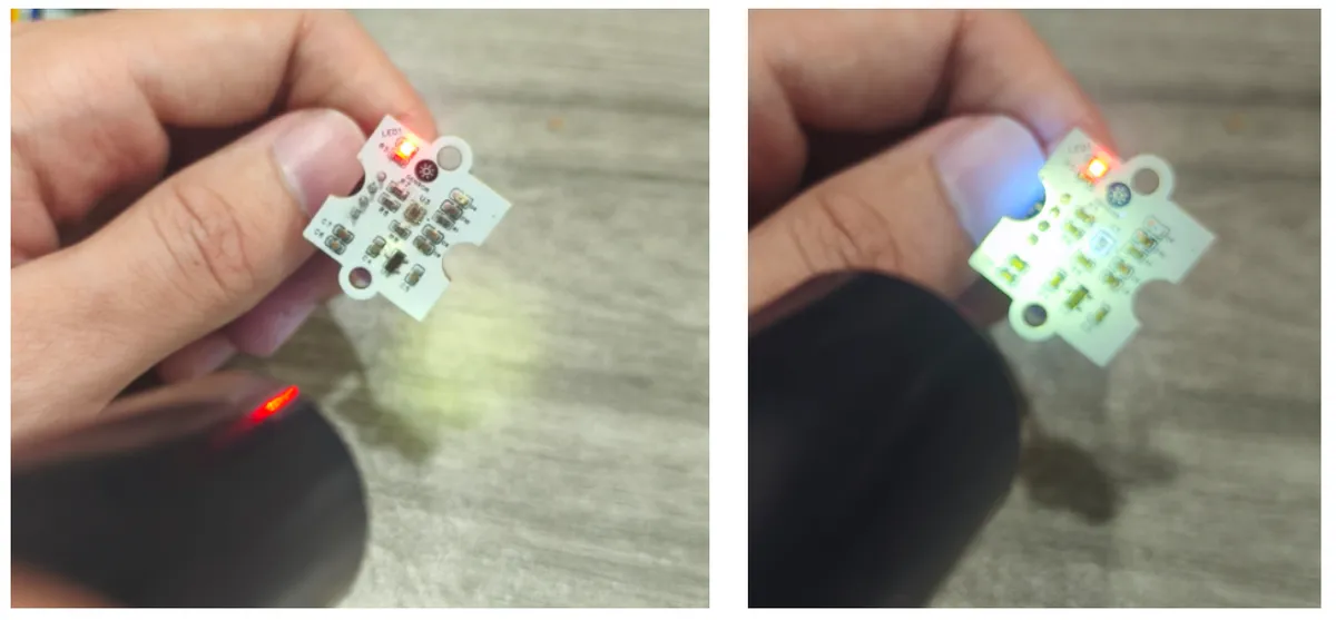
Irradiate the sensor with an ultraviolet lamp to change the value of the terminal sensor:
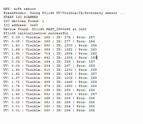
SI1145 UV / Visible / IR / Proximity Sensor features normal I2C communication and initialization, and can stably output four-channel data:
- The ultraviolet (UV) index value fluctuates with changes in ambient light;
- The visible (Visible) and infrared (IR) readings remain stable within a reasonable range;
- The proximity detection (Prox) shows significant value changes when there is an occlusion, with sensitive response and an overall normal working state.
IV. Drivers
si1145_driver-1.0.0.zip 13 KB
5. BOM & Recommended Alternative Parts
None.
VI. Revision History
Document Version | Date Modified | Modifier | Modify Content |
v1.0 | 2026-05-11 | Ling Gaoxing | Initialize the document |
v1.1 | 2026-06-06 | Xin Ruili | Create an open version of the document based on the internal document version v1.0. |
7. Relevant Materials
7.1 Chip Datasheet
SI1145-A10-GMR.pdf 1.4 MB
7.2 Unique Icons for PCB Silk Screen