Contents
- I. Module Introduction
- II. Introduction to Main Chips
- 2.1 Chip Overview
- 2.2 Pin Definition
- 2.3 Functional Block Diagram
- 2.4 Performance Parameters
- 2.5 Reference Circuit
- 2.6 Chip Configuration
- 2.7 Communication Interfaces and Related Protocols
- 2.8 PCB Routing Precautions
- III. Circuit Engineering
- 3.1 Circuit Source Engineering
- 3.2 Module Usage Instructions
- 3.3 Application Experiment
- IV. Drivers
- 5. BOM & Recommended Alternative Parts
- VI. Revision History
- 7. Relevant Materials
- 7.1 Chip Datasheet
- 7.2 Unique Icons for PCB Silk Screen
I. Module Introduction
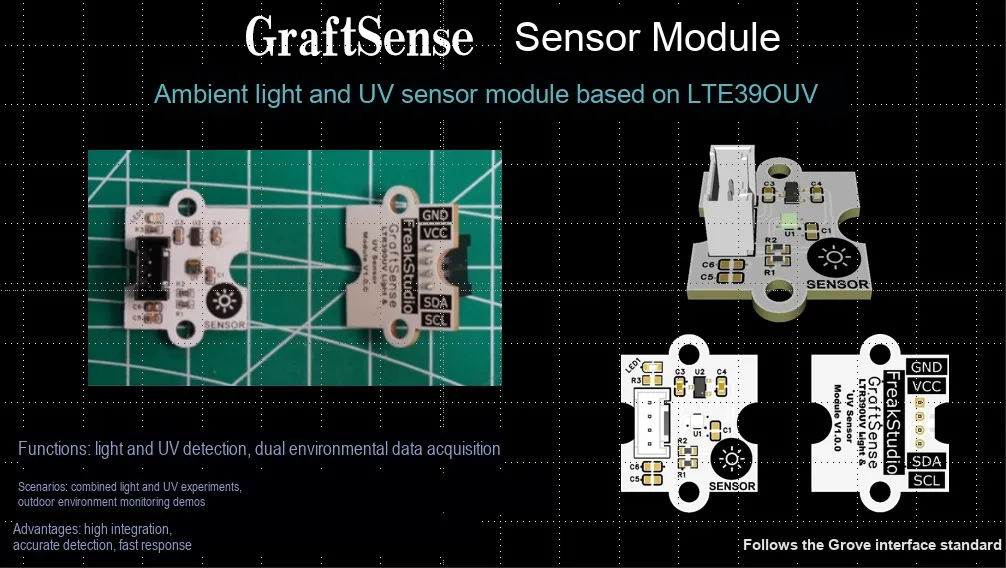
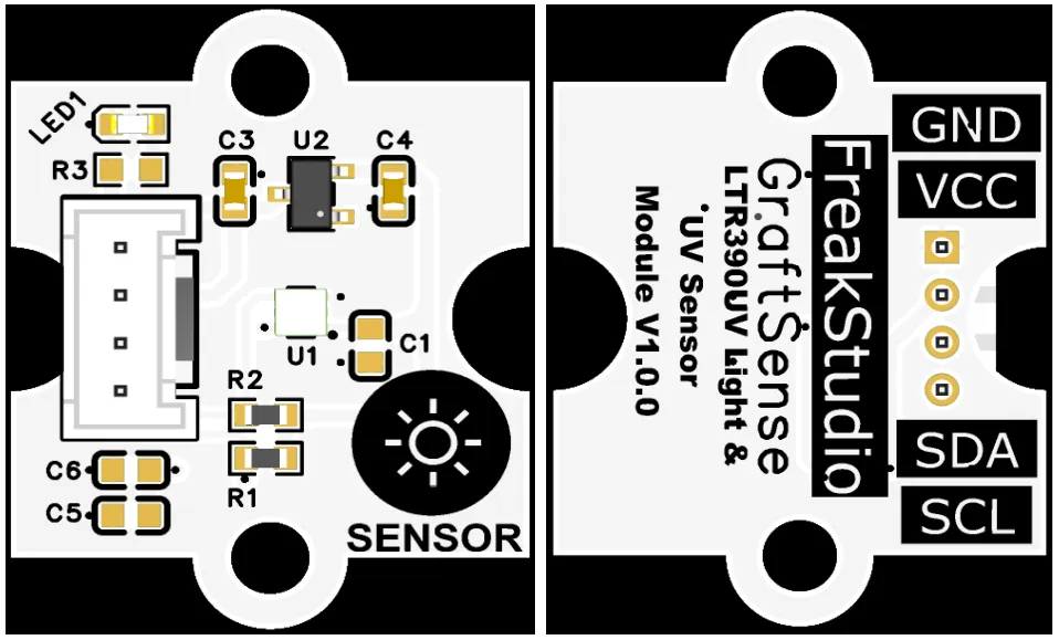
An ambient light and ultraviolet sensor module based on LTR390UV adopts the integrated two-in-one sensor solution of ams OSRAM LTR390UV, which integrates a photosensitive unit and a high-precision ADC, and can simultaneously detect the intensity of UVA / UVB ultraviolet rays (outputting the UVI index) and ambient light intensity (in lux);The module is equipped with LDO voltage regulator circuit, power filtering and indicator circuit, powered by 3.3V and communicates with the main controller via the I²C interface. It supports 13~20bit resolution, programmable threshold interrupt and temperature compensation, features low power consumption, and is suitable for scenarios such as wearable devices, outdoor monitoring and portable devices.
II. Introduction to Main Chips
LTR390UV is LiteOn 's integrated ambient light ( ALS ) and ultraviolet ( UVS ) sensor , which adopts a 2 × 2mm ultra-small package, I ² C interface, low power consumption, can synchronously detect visible light and UVA / UVB bands, built-in 18-bit ADC and temperature compensation, suitable for consumer electronics and outdoor UV detection.
2.1 Chip Overview
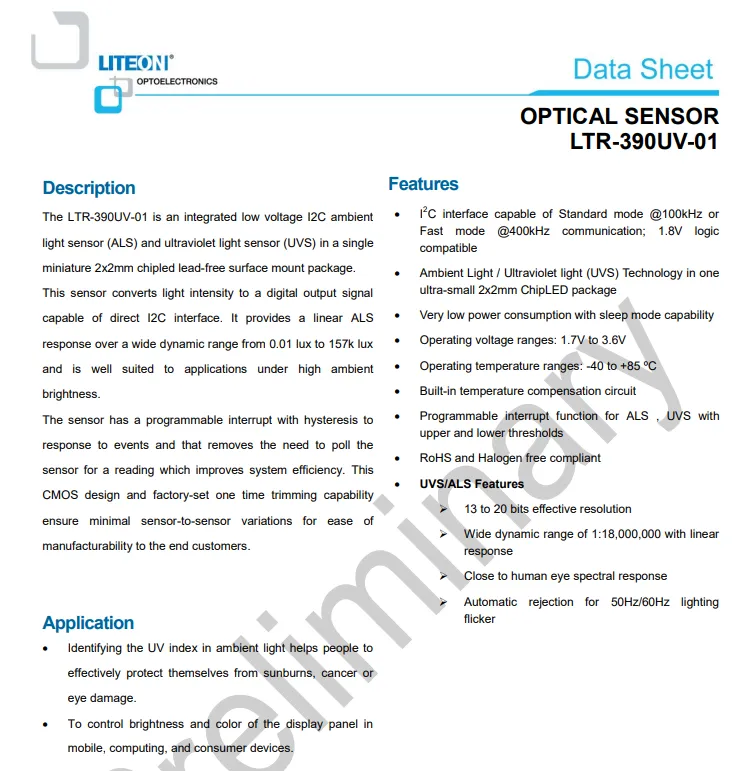
LTR-390UV-01 is Lite-On 's integrated ambient light (ALS) and ultraviolet (UVS) sensor. It features a compact 2×2mm package, supports I²C standard/fast mode, operates on a 1.7~3.6V power supply, and incorporates built-in temperature compensation and programmable interrupt. The ALS has a linear range of 0.01~157k lux, offers human-eye-matched spectral response and 50/60Hz flicker suppression, and can be applied for UV index detection and display brightness control in consumer electronics.
2.2 Pin Definition
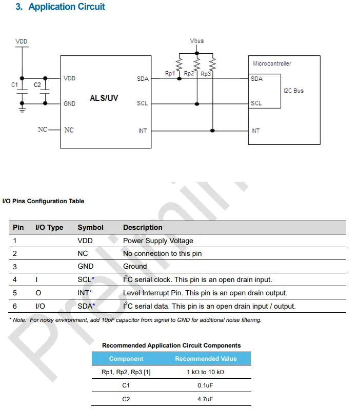
LTR-390UV-01 has its power supply terminal VDD filtered by parallel-connected 0.1μF and 4.7μF capacitors;I²C interface pins SDA / SCL feature an open-drain structure and require an external 1~10kΩ pull-up resistor;INT is an open-drain interrupt output pin that can be directly connected to a microcontroller; it is recommended to add a 10pF capacitor to ground for the signal pins in noisy environments to improve anti-interference performance.
2.3 Functional Block Diagram
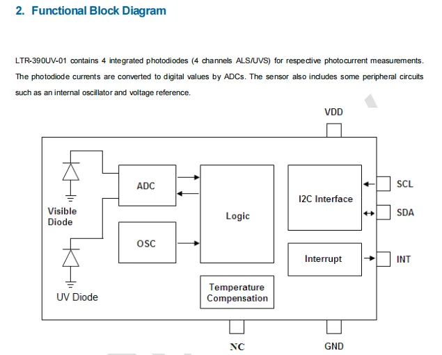
LTR-390UV-01 collects ambient light and ultraviolet light signals respectively through its built-in visible light and ultraviolet photodiodes; after being converted into digital values by ADC, the signals are processed by the logic unit in conjunction with the internal oscillator, voltage reference and temperature compensation circuit, and finally output data via the I²C interface, while a programmable interrupt signal can be provided through the INT pin.
2.4 Performance Parameters
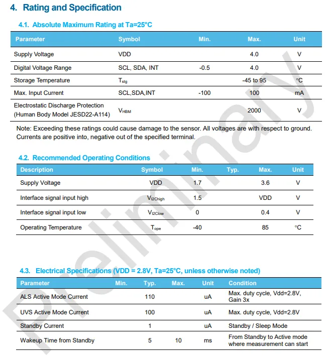
LTR-390UV-01 has both the supply voltage and the withstand voltage of its digital signal pins not exceeding 4.0V, ESD protection capability reaches 2000V (HBM); the recommended operating conditions are 1.7~3.6V power supply and a temperature range of -40~85℃; in terms of typical operating current, the ALS / UVS modes are 110μA/100μA respectively, the standby current is as low as 1μA, and the time from standby wake-up to measurable state is approximately 5~10ms.
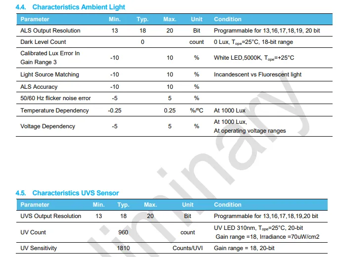
LTR-390UV-01 integrates ambient light (ALS) and ultraviolet (UVS) detection functions. For the ALS, the resolution can be configured from 13 to 20 bits, with a typical error within ±10%, supports 50/60Hz strobe suppression, and has a temperature drift as low as ±0.25%/℃; for the UVS, the resolution also supports 13 to 20 bits, it outputs approximately 960 counts under 310nm ultraviolet light at 70µW/cm², with a typical sensitivity of 1810 Counts/ UVI.
2.5 Reference Circuit
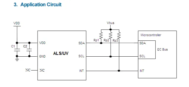
The power supply terminal of LTR-390UV is filtered and regulated via 0.1μF and 4.7μF capacitors. The I²C bus (SDA / SCL) is externally connected with pull-up resistors Rp1 / Rp2 to enable open-drain communication. The INT interrupt pin is directly connected to the microcontroller to realize the acquisition, transmission and event triggering of ambient light and ultraviolet data.
2.6 Chip Configuration
None.
2.7 Communication Interfaces and Related Protocols
2.7.1 I2C Communication
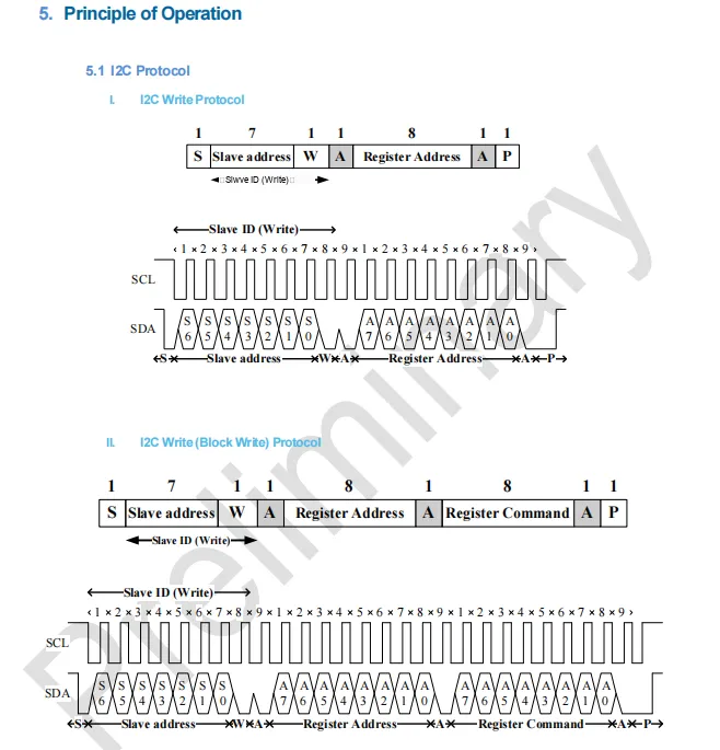
LTR-390UV 's I²C write protocol supports two modes: In the basic single-byte write mode, the master sends a start bit, a slave address (write bit), and a register address, then sends a stop bit after receiving an ACK; in the burst write mode, the master continues to send a register command byte following the register address to complete multi-byte writing, the whole process is clock-synchronized by SCL, SDA transmits data and ACK signals.
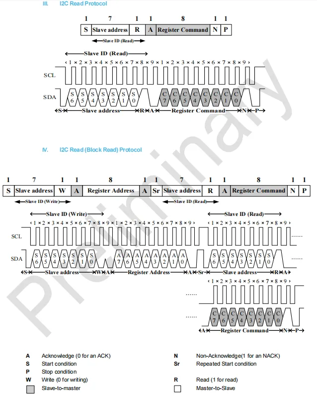
LTR-390UV in single-byte read mode, after the host sends a start bit, a read address and receives the slave's acknowledgment, it reads the register command byte, and finally sends NACK and a stop bit; in block read mode, the register address is first sent via a write operation, then switched to read mode by a repeated start bit to continuously read multiple data bytes, the whole process is synchronized by the SCL clock, and the host terminates the transmission with a NACK.
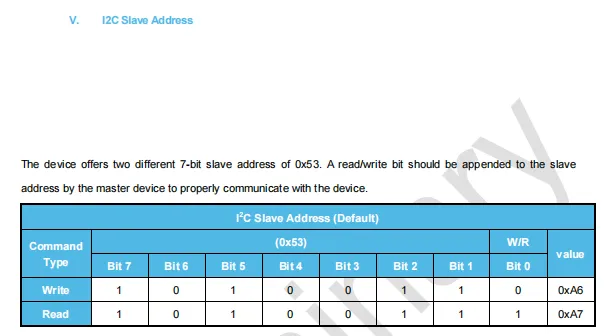
The 7-bit base address of the I²C slave address of LTR-390UV is 0x53. The master needs to append the read/write bit to form the complete address: the value for write operation is 0xA6 (with the least significant bit being 0), and the value for read operation is 0xA7 (with the least significant bit being 1).
2.7.2 Registers
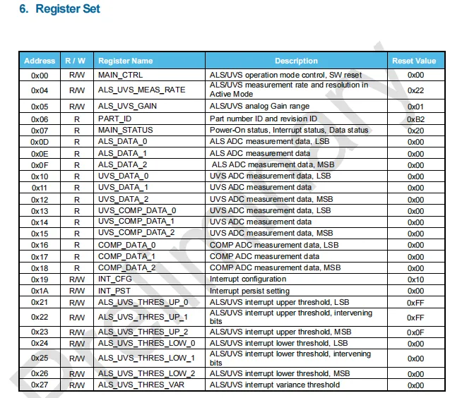
LTR-390UV register list, covering control, measurement, data and interrupt registers: MAIN_CTRL (0x00) controls the operating mode and reset, ALS_UVS_MEAS_RATE (0x04) and ALS_UVS_GAIN (0x05) configure the sampling rate and gain;ALS_DATA and UVS_DATA series registers store 16-bit ambient light and ultraviolet ADC results;INT_CFG and other registers are used to set the interrupt threshold and trigger conditions, and some registers (such as PART_ID) are read-only for chip identification and status query.
2.7.2.1 MAIN_CTRL Control Register (Address: 0x00, Default Value: 0x00)
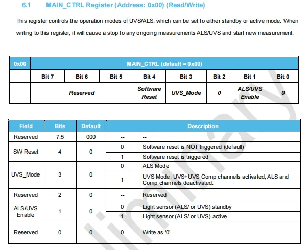
LTR-390UV 's MAIN_CTRL control register (address 0x00, default value 0x00) is used to configure the sensor' s operating mode: Bit4 triggers a software reset, Bit3 (UVS_Mode) selects the ALS or UVS channel, and Bit1 (ALS / UVS Enable) controls the sensor to enter standby or active state; writing to this register will abort the current measurement and initiate a new measurement process.
2.7.2.2 ALS_UVS_MEAS_RATE Register (Address 0x04, Default Value 0x22)
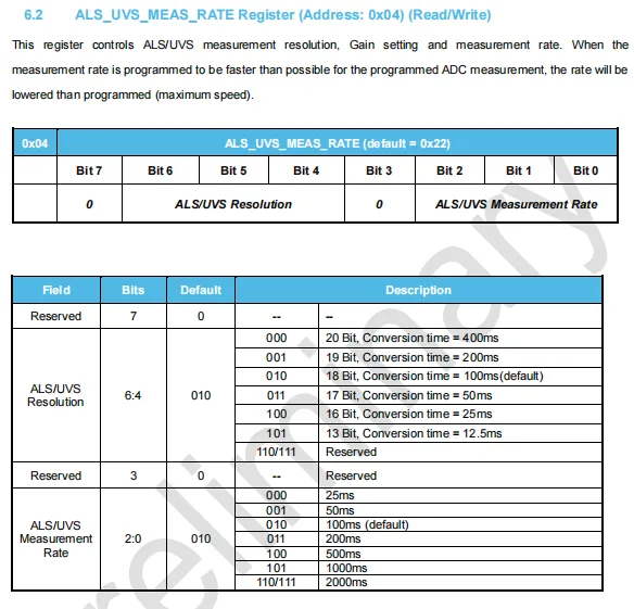
LTR-390UV ALS_UVS_MEAS_RATE register (address 0x04, default value 0x22) is used to configure the sensor's ADC resolution and measurement rate: Bits 6:4 set the resolution (13~20 bits, corresponding to 12.5~400ms conversion time, default 18 bits / 100ms), and Bits 2:0 set the measurement period (25~2000ms, default 100ms);If the set rate is faster than the conversion time of the selected resolution, the sensor will automatically reduce to the maximum speed actually supported for operation.
2.7.2.3 ALS_UVS_GAIN Gain Control Register (Address: 0x05, Default Value: 0x01)
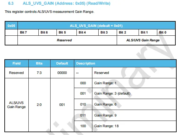
LTR-390UV ALS_UVS_GAIN gain control register (address 0x05, default value 0x01) is used to set the analog gain of the ALS / UVS channel: Bit2:0 can be configured as 1x, 3x (default), 6x, 9x or 18x, and the upper bits Bit7:3 are reserved bits.
2.7.2.4 PART_ID Register (Address 0x06, Default Value 0xB2)
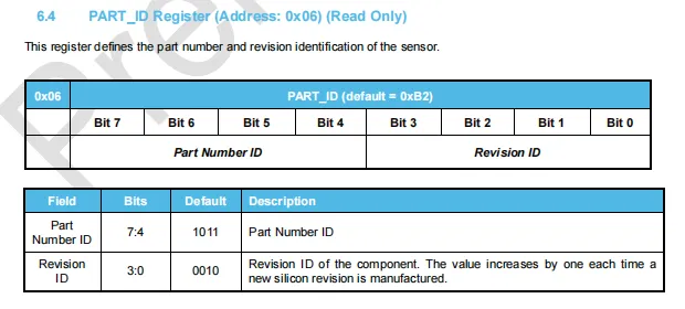
LTR-390UV 's read-only PART_ID register (address 0x06 , default value 0xB2 ) for chip identification: the high 4 bits 1011 are the product number ID , the low 4 bits 0010 are the version number ID , and the version number will be incremented by 1 every time the silicon version is updated.
2.7.2.5 MAIN_STATUS Status Register (Address 0x07, Default Value 0x20)
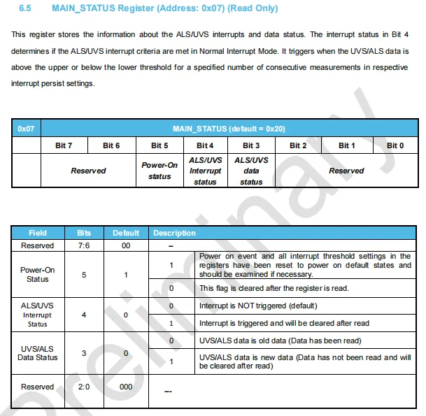
LTR-390UV 's read-only MAIN_STATUS status register (address 0x07 , default value 0x20 ) is used to feedback the sensor's operating status: Bit5 is the power-on status flag, automatically cleared after reading the register; Bit4 is the ALS / UVS interrupt status, set to 1 when triggered, cleared after the read operation; Bit3 is the data status, set to 1 indicates the presence of unread new data, cleared after the read operation; the remaining bits are reserved bits.
2.7.2.6 Ambient Light Data Register (ALS_DATA, addresses 0x0D / 0x0E / 0x0F, all read-only)
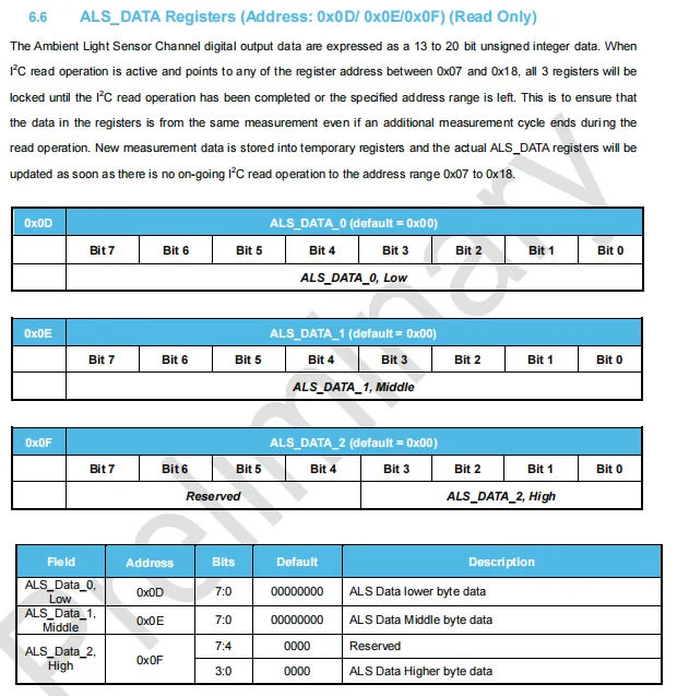
LTR-390UV ambient light data register (ALS_DATA, addresses 0x0D / 0x0E / 0x0F, all read-only): the 13~20-bit ambient light ADC result is stored in three segments, where 0x0D is the low byte, 0x0E is the middle byte, and the lower 3 bits of 0x0F serve as the high byte;I²C will lock this set of registers when reading the address range from 0x07 to 0x18 to ensure that the data read belongs to the same measurement cycle, and the registers will be automatically unlocked and updated after the read operation is completed.
2.7.2.7 Ultraviolet Data Register (UVS_DATA, Address 0x10 / 0x11 / 0x12, Read-Only)
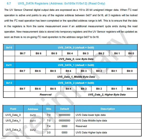
LTR-390UV has an ultraviolet data register (UVS_DATA, addresses 0x10 / 0x11 / 0x12, read-only), where the 16th to 20th bits of the ultraviolet ADC result are stored in three segments: 0x10 is the low byte, 0x11 is the middle byte, and the lower 3 bits of 0x12 serve as the high byte; when I²C reads the address range from 0x07 to 0x18, this set of registers will be locked to ensure that the read data comes from the same measurement cycle, and new data will be temporarily stored in a temporary register and updated after the read operation is completed.
2.7.2.8 UV Compensation Channel Data Register (UVS_COMP_DATA, Address 0x13 / 0x14 / 0x15, Read-Only)
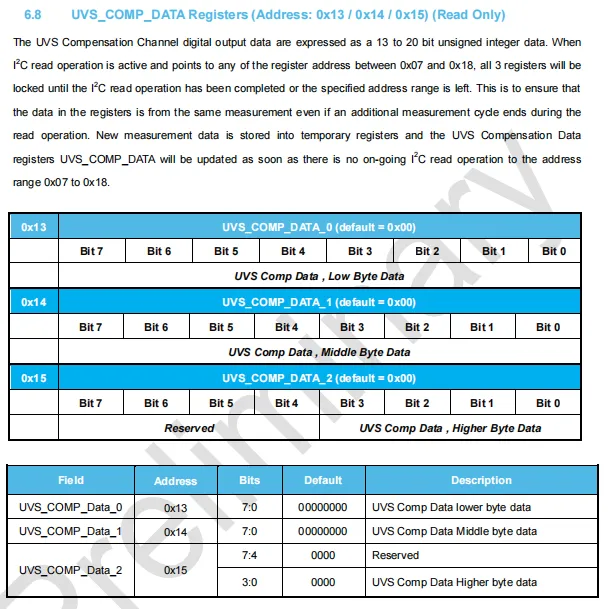
LTR-390UV has an ultraviolet compensation channel data register (UVS_COMP_DATA, addresses 0x13 / 0x14 / 0x15, read-only), where the 8-bit compensation channel ADC result spanning bits 13 to 20 is stored in three segments: 0x13 holds the low byte, 0x14 holds the middle byte, and the lower 3 bits of 0x15 hold the high byte; when I²C reads the address range from 0x07 to 0x18, this set of registers will be locked to ensure the read data comes from the same measurement cycle, and new data is temporarily stored in a temporary register to be updated after the read operation is completed.
2.7.2.9 Ambient Light Compensation Channel Data Register (COMP_DATA, Address 0x16/ 0x17 / 0x18, Read-Only)
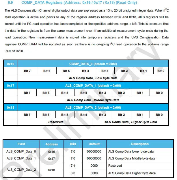
LTR-390UV 's ambient light compensation channel data register (COMP_DATA, addresses 0x16/ 0x17 / 0x18, read-only) stores the 13~20-bit compensation channel ADC result in three segments: 0x16 is the low byte, 0x17 is the middle byte, and the lower 3 bits of 0x18 form the high byte. When I²C reads the address range from 0x07 to 0x18, this register set will be locked to ensure that the read data comes from the same measurement cycle; new data will be temporarily stored in a temporary register and updated after the read operation is completed.
2.7.2.10 INT_CFG Interrupt Configuration Register (Address: 0x19, Read/Write, Default Value: 0x10)
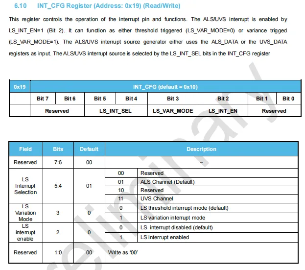
LTR-390UV 's INT_CFG interrupt configuration register (address 0x19, read/write, default value 0x10) is used to control the interrupt function: Bit2 (LS_INT_EN) is the interrupt enable bit, Bit3 (LS_VAR_MODE) selects threshold trigger or difference trigger mode, Bit5:4 (LS_INT_SEL) selects the interrupt source as the ALS channel (default) or UVS channel, and the remaining bits are reserved.
2.7.2.11 INT_PST Interrupt Persistence Register (Address: 0x1A, Read/Write, Default Value: 0x00)
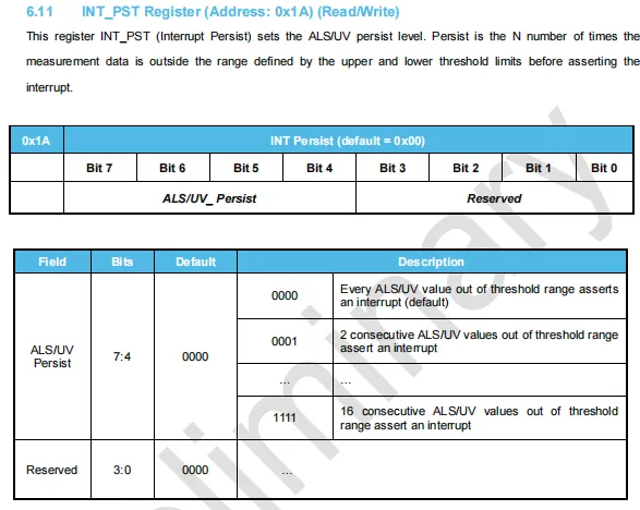
LTR-390UV INT_PST Interrupt Persistence Register (address 0x1A, read/write, default value 0x00), which is used to set the consecutive times of interrupt triggering: Bit7 to 4 define the ALS / UV_Persist value, ranging from 0000 to 1111 (corresponding to triggering an interrupt after 1 to 16 consecutive measurements exceed the threshold range; the default 0000 means triggering an interrupt whenever the threshold is exceeded), and the lower 4 bits are reserved bits.
2.7.2.12 Interrupt Threshold Register (UVS / ALS_THRES)
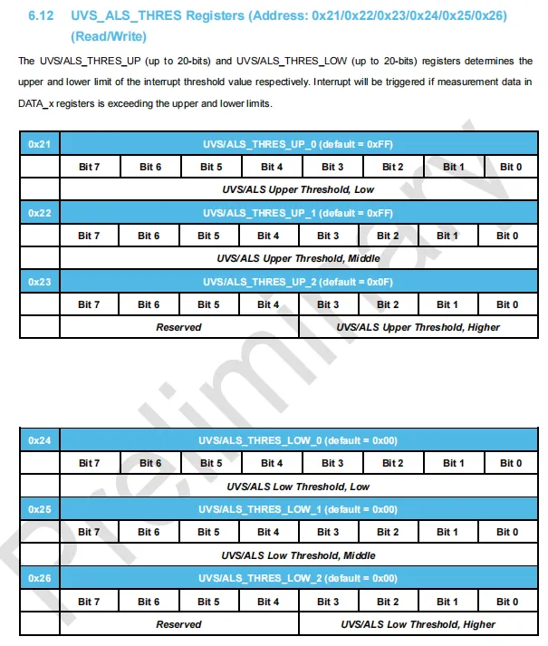
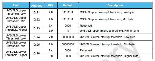
LTR-390UV interrupt threshold registers (UVS / ALS_THRES), located at addresses 0x21 to 0x26, are readable and writable, and are used to configure the upper and lower limit trigger conditions for the ALS / UVS channels: the upper threshold consists of 0x21 (low byte), 0x22 (middle byte), and the lower 4 bits of 0x23 (high byte), with a default value of 0xFFFFF;The lower threshold consists of 0x24 (low byte), 0x25 (middle byte), and the lower 4 bits of 0x26 (high byte), with a default value of 0x00000; an interrupt is triggered when the measured data exceeds the set range.
2.7.2.13 UVS_ALS_THRES_VAR Difference Interruption Threshold Register (Address: 0x27, Read/Write, Default Value: 0x00)
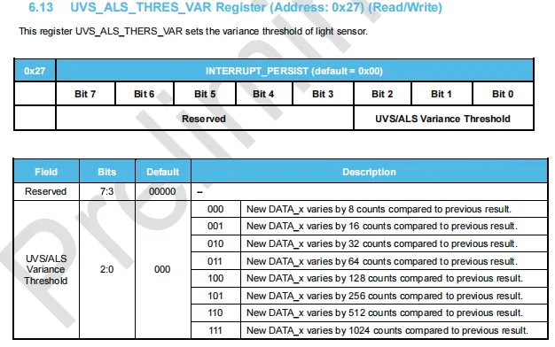
LTR-390UV UVS_ALS_THRES_VAR differential interrupt threshold register (address 0x27, read-write, default value 0x00) is used to configure the trigger condition in differential mode: Bit2 to Bit0 set the differential threshold for adjacent measurement data, which can be selected from 8,16,32,64,128,256,512 or 1024 counts; the high-order Bit7 to Bit3 are reserved bits.
2.8 PCB Routing Precautions
None.
III. Circuit Engineering
3.1 Circuit Source Engineering
To obtain the source code of the circuit, please follow the official account [Freak Embedded]
3.2 Module Usage Instructions
The schematic diagram of this module is shown below:
SCH_Schematic1_Ambient Light and UV Sensor Module Based on LTR390UV_v1.0.0_2026-05-11.pdf 2.1 MB
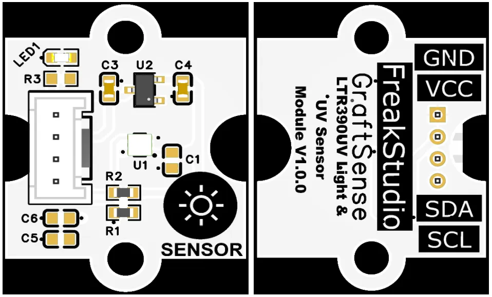
This module provides an IIC communication interface: it supports standard I2C communication rates, is compatible with 3.3V logic level, and can stably transmit the digital signals of LTR390UV collected UVA / UVB ultraviolet index and ambient light intensity. It is suitable for scenarios such as wearable devices, outdoor monitoring, and portable devices, providing the system with reliable 2-in-1 optical sensing data interaction capability.
3.3 Application Experiment
Here, we use the GraftPort-RP2040 development board for testing, and the LTR390UV-based ambient light and ultraviolet sensor module uses the I2C interface to communicate with the main controller.
Here, we first use the HY2.0-4P cable to connect the module to the GraftPort-RP2040 development board's I2C0 interface:
Development Board Pins | Module Pins | Description |
Pin 4 |
|
|
Pin 5 |
|
|
Here, we need to search for the relevant driver packages on uPyPI: https://upypi.net/zh/
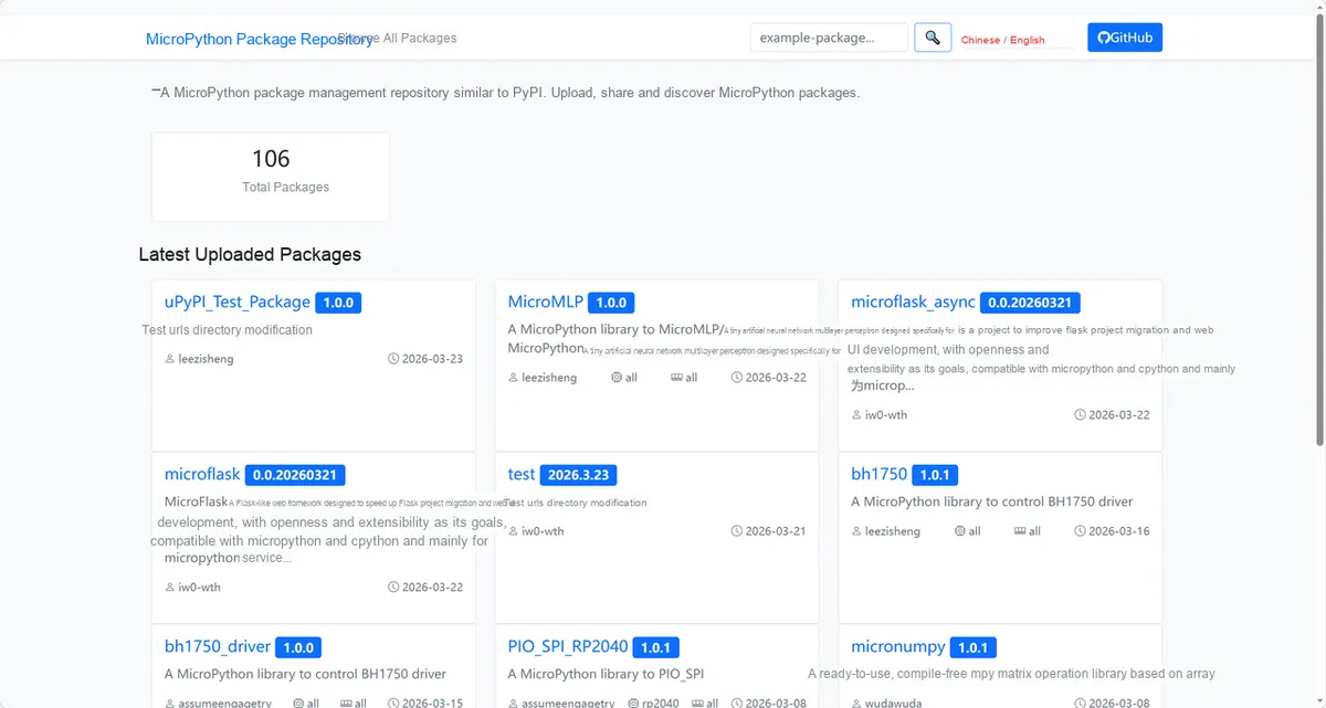
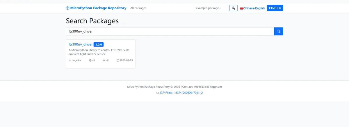
Enter ltr390uv_driver to search, and the following will be displayed:
Click to copy the local installation command:
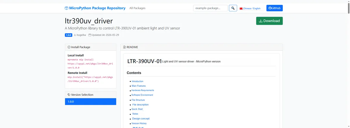
Import the module driver library code via the mip tool. Below are the usage commands for the mpremote tool:
mpremote mip install https://upypi.net/pkgs/ltr390uv_driver/1.0.0Import the ambient light and ultraviolet sensor module based on LTR390UV - MicroPython driver code, then copy the following main.py code into our project:
# Python env   : MicroPython v1.23.0
# -*- coding: utf-8 -*-
# @Time    : 2026/4/16 PM 2:30
# @Author  : MicroPython Developer
# @File    : main.py
# @Description : LTR390UV UV/ambient light sensor I2C auto-scan and data acquisition program


# ======================================== Import Modules =========================================

import sys
from machine import Pin, SoftI2C
from sensor_pack_2.bus_service import I2cAdapter
import ltr390uv
import time


# ======================================== Global Variables ============================================

# Automatically identify the sensor address, define a global target address list (supports multiple addresses; use [] even for a single one)
TARGET_SENSOR_ADDRS = [0x53]  # LTR390UV default address

# I2C initialization (compatible with I2C/SoftI2C)
I2C_SDA_PIN = 4
I2C_SCL_PIN = 5
I2C_FREQ = 400_000


# ======================================== Functions ============================================


def show_header(caption: str, symbol: str = "*", count: int = 40):
    """
    Print a separator header
    Args: caption - title text; symbol - separator character; count - number of separator repetitions

    Raises: None

    Notes: Used to output a clear section marker on the console

    ==========================================
    Print a formatted header line
    Args: caption - title text; symbol - separator character; count - repetition count

    Raises: None

    Notes: Used to output clear section markers in console
    """
    print(count * symbol[0])
    print(caption)
    print(count * symbol[0])


# ======================================== Custom Classes ============================================


# ======================================== Initialization configuration ===========================================

time.sleep(3)
print("FreakStudio: LTR390UV sensor auto scan and data acquisition")
i2c_bus = SoftI2C(sda=Pin(I2C_SDA_PIN), scl=Pin(I2C_SCL_PIN), freq=I2C_FREQ)
# Start scanning for devices on the I2C bus
devices_list: list[int] = i2c_bus.scan()
print("START I2C SCANNER")

# Check the I2C device scan result
if len(devices_list) == 0:
    print("No i2c device !")
    raise SystemExit("I2C scan found no devices, program exited")
else:
    print("i2c devices found:", len(devices_list))

# Iterate over the address list to initialize the target sensor
sensor = None  # Placeholder for the sensor object initialization
for device in devices_list:
    if device in TARGET_SENSOR_ADDRS:
        print("I2c hexadecimal address:", hex(device))
        try:
            # Automatically identify and initialize the corresponding sensor
            adapter = I2cAdapter(i2c_bus)
            sensor = ltr390uv.LTR390UV(adapter=adapter)
            print("Sensor initialization successful")
            break
        except Exception as e:
            print(f"Sensor Initialization failed: {e}")
            continue
else:
    # Target device not found, raise an exception
    raise Exception("No target sensor device found in I2C bus")


# ========================================  Main Program  ============================================

# Use the already initialized sensor object
als = sensor

# Read the sensor ID information
_id = als.get_id()
print(f"Part number id: {_id[0]}; Revision id: {_id[1]};")
# Perform a software reset
als.soft_reset()
print("Software reset successfully!")

# Start ALS measurement mode (ambient light)
als.start_measurement(uv_mode=False)
# Get the conversion cycle time
cct_ms = als.get_conversion_cycle_time()
# Print the current configuration parameters
print(f"uv_mode: {als.uv_mode}")
print(f"meas_rate: {als.meas_rate}")
print(f"resolution: {als.resolution}")
print(f"gain: {als.gain}")
# Get the sensor status
status = als.get_status()
print(status)

# Display the ALS mode header
show_header(f"ALS mode. LUX out! uv_mode: {als.uv_mode}")

# Loop to acquire ambient light data 1000 times
for i in range(1000):
    time.sleep_ms(cct_ms)
    print(f"lux: {als.get_illumination(raw=False)}")

# Switch to UV measurement mode
als.start_measurement(uv_mode=True)
# Re-obtain the conversion cycle time
cct_ms = als.get_conversion_cycle_time()

# Display the UV mode header
show_header(f"UV mode. RAW only out! uv_mode: {als.uv_mode}")

# Initialize the counter
cnt = 0
# Iterate to acquire raw UV data
for raw in als:
    time.sleep_ms(cct_ms)
    print(f"raw: {raw}")
    cnt += 1
    # Exit the program after 3000 acquisitions
    if cnt > 3_000:
        sys.exit(0)
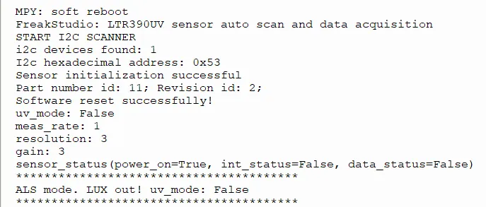
Burn the code, open the terminal, and the output is as follows:
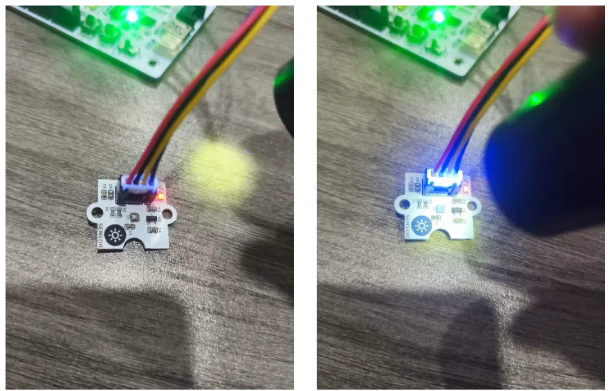
Irradiate the sensor with an ultraviolet lamp:
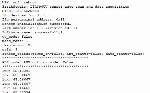
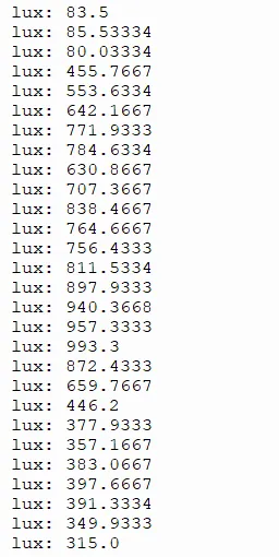
The LTR390UV sensor functions properly in I2C communication and initialization. When operating in ALS mode, it can stably output illumination intensity (lux) data, with readings fluctuating significantly in response to changes in ambient light, indicating normal operating response.
IV. Drivers
ltr390uv_driver-1.0.0.zip 31 KB
5. BOM & Recommended Alternative Parts
None.
VI. Revision History
Document Version | Date Modified | Modifier | Modify Content |
v1.0 | 2026-05-11 | Ling Gaoxing | Initialize the document |
v1.1 | 2026-06-06 | Xin Ruili | Create an open version of the document based on the internal document version v1.0. |
7. Relevant Materials
7.1 Chip Datasheet
LTR390UV.pdf 1.2 MB
7.2 Unique Icons for PCB Silk Screen