Contents
- I. Module Introduction
- II. Introduction to Main Chips
- 2.1 Chip Overview
- 2.2 Pin Definition
- 2.3 Functional Block Diagram
- 2.4 Performance Parameters
- 2.5 Reference Circuit
- 2.6 Chip Configuration
- 2.7 Communication Interfaces and Related Protocols
- 2.8 PCB Routing Precautions
- III. Circuit Engineering
- 3.1 Circuit Source Engineering
- 3.2 Module Usage Instructions
- 3.3 Application Experiment
- IV. Drivers
- 5. BOM & Recommended Alternative Parts
- VI. Revision History
- 7. Relevant Materials
- 7.1 Chip Datasheet
- 7.2 Unique Icons for PCB Silk Screen
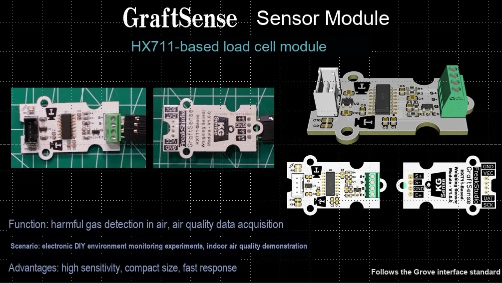
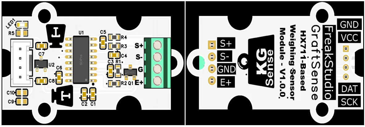
I. Module Introduction
Weighing sensor module based on HX711, which adopts HX711 high-precision 24-bit A / D conversion chip solution, has a built-in low-noise programmable gain amplifier that can convert the weak analog signal of the weighing sensor into a digital signal; the module is equipped with LDO voltage regulator circuit, power filtering and indicator circuit, powered by 3.3V/5V, communicates with the main controller through a two-wire serial interface, adapts to resistance strain gauge weighing sensors with different sensitivities, has strong anti-interference ability, and is suitable for scenarios such as electronic scales, pressure detection, industrial weighing and DIY force measuring equipment.
II. Introduction to Main Chips
HX711 is a 24-bit high-precision analog-to-digital conversion chip specifically designed for load cells. It integrates dual-channel differential inputs, a programmable gain amplifier, and a regulated power supply, featuring a simple interface and low cost, and is widely used in electronic scales.
2.1 Chip Overview
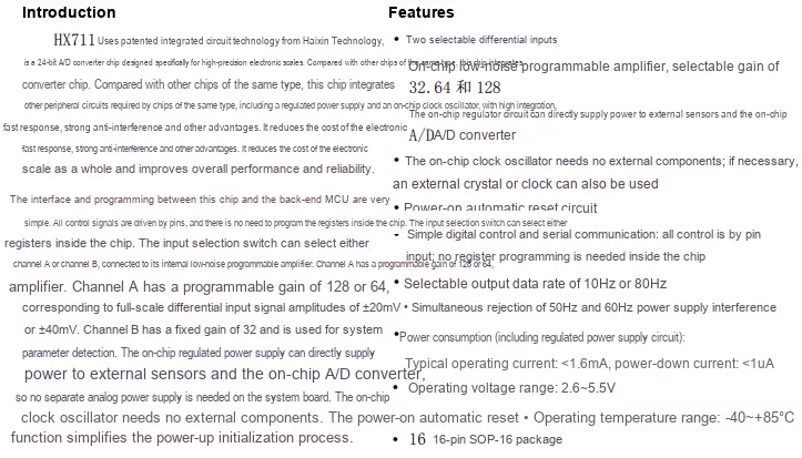
HX711 is a 24-bit A / D converter chip designed specifically for high-precision electronic scales. It integrates a regulated power supply, a clock oscillator, and a low-noise programmable amplifier (with a gain of 64/128 for Channel A and a fixed gain of 32 for Channel B). It supports dual-channel differential input, 10Hz/80Hz data rate, and 50/60Hz power supply interference rejection. Featuring a simple interface that requires no register programming, it operates at a supply voltage of 2.6~5.5V, boasts low power consumption, and is packaged in SOP-16 package.
2.2 Pin Definition
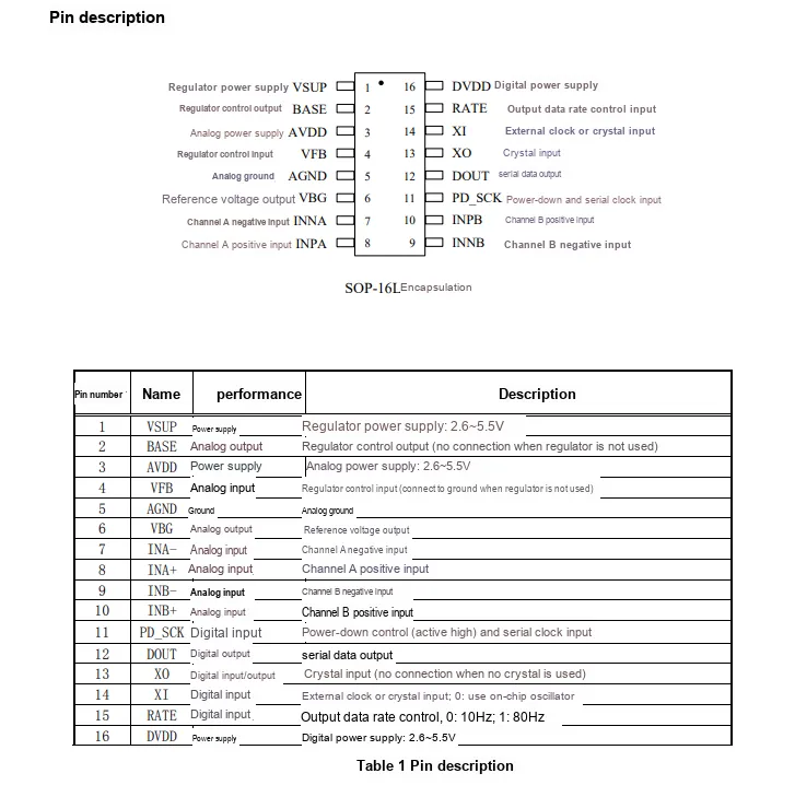
HX711 is SOP-16 packaged, with core pin functions as follows: Pin 1/16 serves as power supply (VSUP / DVDD), Pin 3 is analog power supply AVDD; Pins 7/8 are differential inputs for Channel A, Pins 9/10 are differential inputs for Channel B; Pin 11 (PD_SCK) controls power-down and serial clock, Pin 12 (DOUT) is the data output pin; Pin 15 (RATE) selects 10Hz/80Hz data rate; the remaining pins are related to voltage regulation, clock and ground.
2.3 Functional Block Diagram
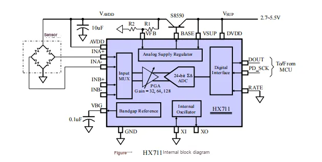
HX711 receives the differential signal from an external weighing sensor through the A / B channel. After being switched by the internal multiplexer, the signal is sent to a programmable gain amplifier (with selectable gains of 32,64, or 128 times). The amplified signal is converted from analog to digital by a 24-bit Σ-Δ type ADC, and then communicates with the MCU via the digital interface through the DOUT and PD_SCK pins. Meanwhile, the on-chip voltage regulator, bandgap reference, and oscillator provide stable power supply, reference voltage, and clock signals for the entire system, enabling high-precision weight Data Acquisition.
2.4 Performance Parameters
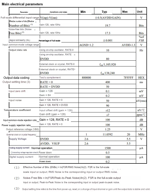
HX711 has core parameters as follows: the 24-bit ADC features an effective resolution of 19.7 bits, a noise-free resolution of 17.3 bits, and an integral nonlinearity of ±0.001% FSR when operating at a gain of 128 and a rate of 10Hz; it supports 10/80Hz data rates, with an input noise as low as 50nV (rms), and both power supply and common-mode rejection ratios reach 100dB; its typical reference voltage is 1.25V, power supply voltage ranges from 2.6V to 5.5V, and the operating current is approximately 1500μA on the analog side and around 100μA on the digital side.
2.5 Reference Circuit
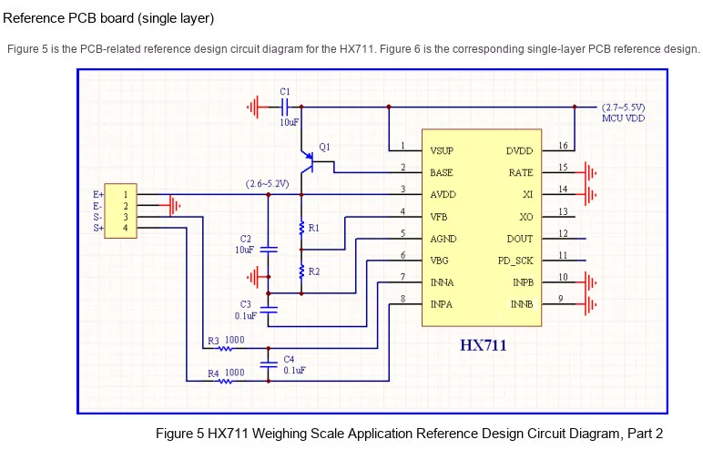
HX711 reference circuit for weighing applications: a 2.6-5.2V power supply supplies the chip's AVDD analog power via a 10uF filter capacitor; the differential signal output from the external weighing sensor is filtered by an RC network and then fed to the A channel's INPA / INNA pins. After internal amplification and 24-bit analog-to-digital conversion, the chip communicates with the DOUT and PD_SCK pins to interface with an MCU to realize weight data acquisition and transmission.
2.6 Chip Configuration
None.
2.7 Communication Interfaces and Related Protocols
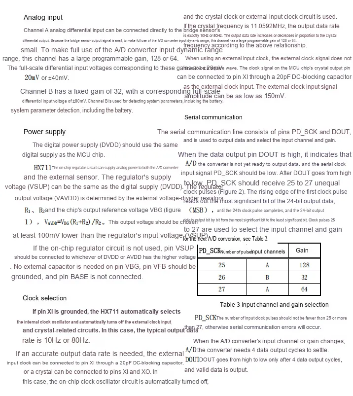
HX711 DOUT being at high level indicates that the data is not ready; after it is pulled low, 24 clock pulses need to be input to read out the 24-bit data;The 25th to 27th pulses are used for channel and gain selection, with different pulse numbers corresponding to different configurations (the 25th corresponds to channel A / gain 128, the 26th corresponds to channel B / gain 32, the 27th corresponds to channel A / gain 64); a pulse count less than 25 or greater than 27 will result in a communication error. After channel/gain switching, 4 output cycles must elapse before DOUT goes low again and outputs valid data.
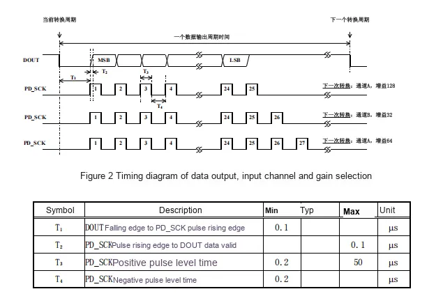
HX711 in the serial communication timing sequence, DOUT being pulled low indicates that data is ready, and the MCU reads the 24-bit data via the PD_SCK; the 25th to 27th clock pulses are used to select the channel and gain for the next conversion, and the number of pulses corresponds respectively to Channel A with a gain of 128, Channel B with a gain of 32, and Channel A with a gain of 64; meanwhile, the high and low levels of PD_SCK must meet the minimum pulse width requirements (high/low level ≥ 0.2μs, time from rising edge to data valid ≤ 0.1μs).
2.8 PCB Routing Precautions
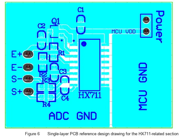
III. Circuit Engineering
3.1 Circuit Source Engineering
To obtain the source code of the circuit, please follow the official account [Freak Embedded]
3.2 Module Usage Instructions
The schematic diagram of this module is shown below:
SCH_Schematic1_Load Cell Module Based on HX711_v1.0.0_2026-05-11.pdf 2.2 MB
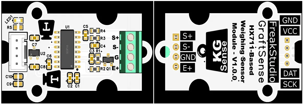
This module provides dual-line serial interfaces DAT and SCK : half-duplex communication using SPI -like protocol, compatible with 3.3V/5V level, and can stably transmit 24-bit high-precision weighing digital signals collected by HX711 , suitable for electronic scales, pressure detection, industrial weighing and DIY force measurement equipment and other scenarios, providing reliable weak weight signal amplification and analog-to-digital conversion data interaction capabilities for the system.
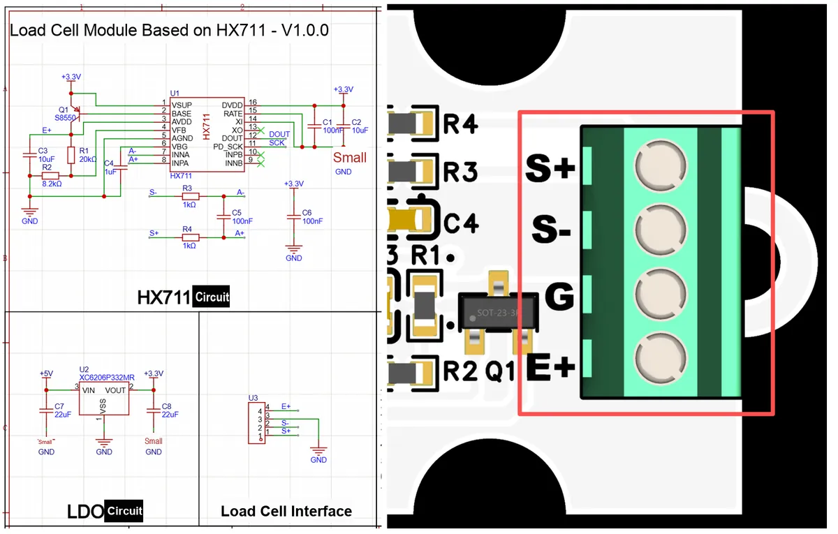
Note that the silkscreen labels of the load cell interface on our HX711 module are S+, S-, G, E+, which differ from the commonly seen E+ / E- / A+ / A- definitions online. The corresponding relationship is as follows:
| Module Silkscreen | Actual Meaning | Corresponding Sensor Wire | Circuit Connection Description |
|---|---|---|---|
| E+ | Excitation Power Positive (Excitation+) | Red wire (power positive, connected to E+) | 3.3V supply output from the module LDO, powers the sensor bridge |
| G | Excitation Power Negative (Excitation-, i.e., E-) | Black wire (power negative, connected to E-) | Connected directly to GND inside the module, provides the negative supply for the sensor bridge |
| S+ | Signal Output Positive (Signal+, i.e., A+) | Green wire (signal positive, connected to S+A) | Connected to the A+ pin (pin 8) of the HX711, as the positive end of the differential signal |
| S- | Signal Output Negative (Signal-, i.e., A-) | White wire (signal negative, connected to S-A) | Connected to the A- pin (pin 7) of the HX711, as the negative end of the differential signal |
It should be noted that the HX711 communication has no protocol and is purely timing-controlled; any timing error will directly lead to data invalidation, so all codes / frameworks must meet the following requirements:
- Clock pulse: The width of the high and low levels of SCK shall be ≥ 0.2μS (a microsecond-level delay is sufficient to meet the requirement);
- Read Timing: After DOUT indicates that the data is ready, the reading must be completed within 10 ms; otherwise, the data will be invalidated.
- Reading process: During data reading, switching the SCK level arbitrarily is prohibited, and the clock shall be output strictly in accordance with the timing sequence of 24-bit data + gain bit;
- Data Judgment: When the DOUT pin is at a low level, it indicates that the ADC conversion is complete and the data is ready to be read.
Before using this module, we need to prepare the following items:
| Item | Purpose | Reference Description |
|---|---|---|
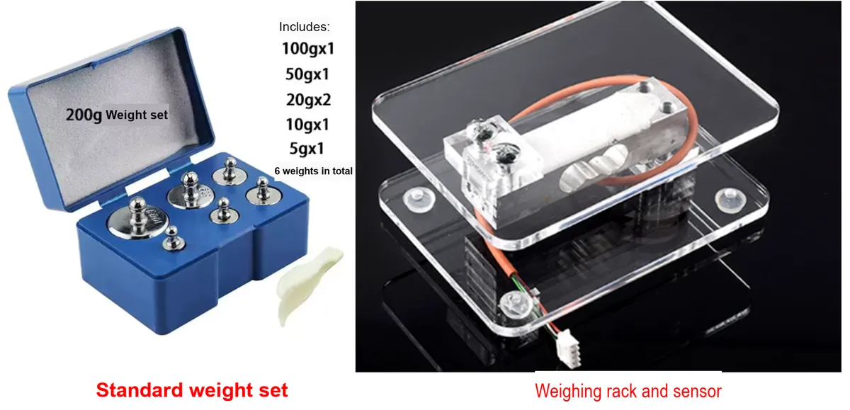
| Cantilever beam load cell | Deforms under force, producing a bridge signal | Common 4-wire type: red / black / green / white |
| Standard weight set | Used for range calibration | At least one weight of known mass is required |
| Weighing stand (optional) | Holds the sensor and keeps the force stable | Without a stand, make sure the sensor is fixed level |
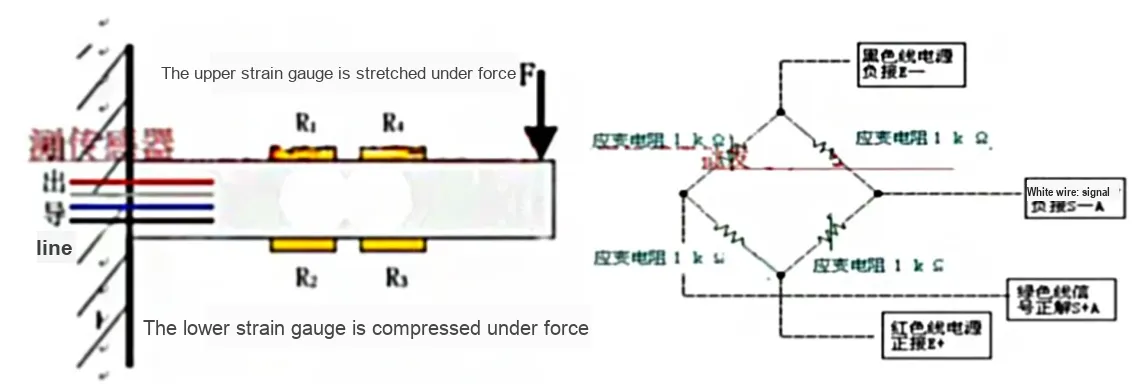
The load sensor adopts a cantilever beam structure, with 4 strain gauges (R1/R2/R3/R4) attached to its surface:
- When a force
Fis applied downward, the beam bends, causing the upper strain gauges R1/R4 to be stretched and their resistance to increase; - The following strain gauges R2/R3 are compressed, resulting in a decrease in their resistance;
- Four strain gauges form a Wheatstone bridge, with power supplied by
E+/E-, and the differential output signal is exported viaS+/S-.
HX711 is a 24-bit high-precision ADC, with its core functions as follows:
- Provide a stable 3.3V excitation power supply for the sensor (output via LDO XC6206);
- Amplify the weak differential signal output by the bridge (default gain: 128x);
- It converts analog signals into 24-bit digital signals and communicates with the main controller via the
DOUT/SCKpins.
After completing the assembly of the weighing frame, the wiring of the modules and weighing sensors, and the wiring of the main controller and modules, wait for the modules to stabilize after power-on, and we first need to perform zero calibration (tare to eliminate no-load error):
- Do not place any object on the sensor to ensure it is in an unloaded state;
- Continuously read the raw ADC values for 10 to 20 times, and calculate the average value;
- Set this average value as the zero offset value (subsequent readings will automatically subtract this value to achieve the "zero reset" effect).
⚠️ After replacing the sensor, mounting position or module, the zero point must be recalibrated!
Next, perform range calibration: place a standard weight of known mass on the sensor, continuously read the raw ADC values for multiple times, calculate the average value and then compute the calibration coefficient:
Calibration factor = (ADC average for weight - zero-point ADC value) / actual weight of the weightSave the calibration coefficients for subsequent conversion of ADC values to weight.
⚠️ Calibration sequence must not be reversed: Zero point calibration must be performed first, followed by range calibration!
When weighing an object, read the real-time 24-bit raw ADC value output of the module. The calculation formula for the actual weight is as follows:
Actual weight = (current ADC value - zero offset value) / calibration factorOf course, this module also supports low-power control:
- Sleep: Pull
SCKpin high, and the HX711 will enter the low-power mode; - Wake-up: Pull the
SCKpin low to restore the module to working state.
3.3 Application Experiment
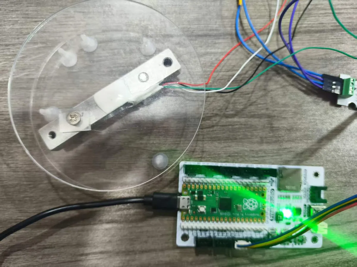
Here, we use the GraftPort-RP2040 development board for testing, and the HX711-based weighing sensor module uses the DIO interface to communicate with the main controller.
Here, we first use the HY2.0-4P connection cable to connect the module to the GraftPort-RP2040 development board's DIO0 interface:
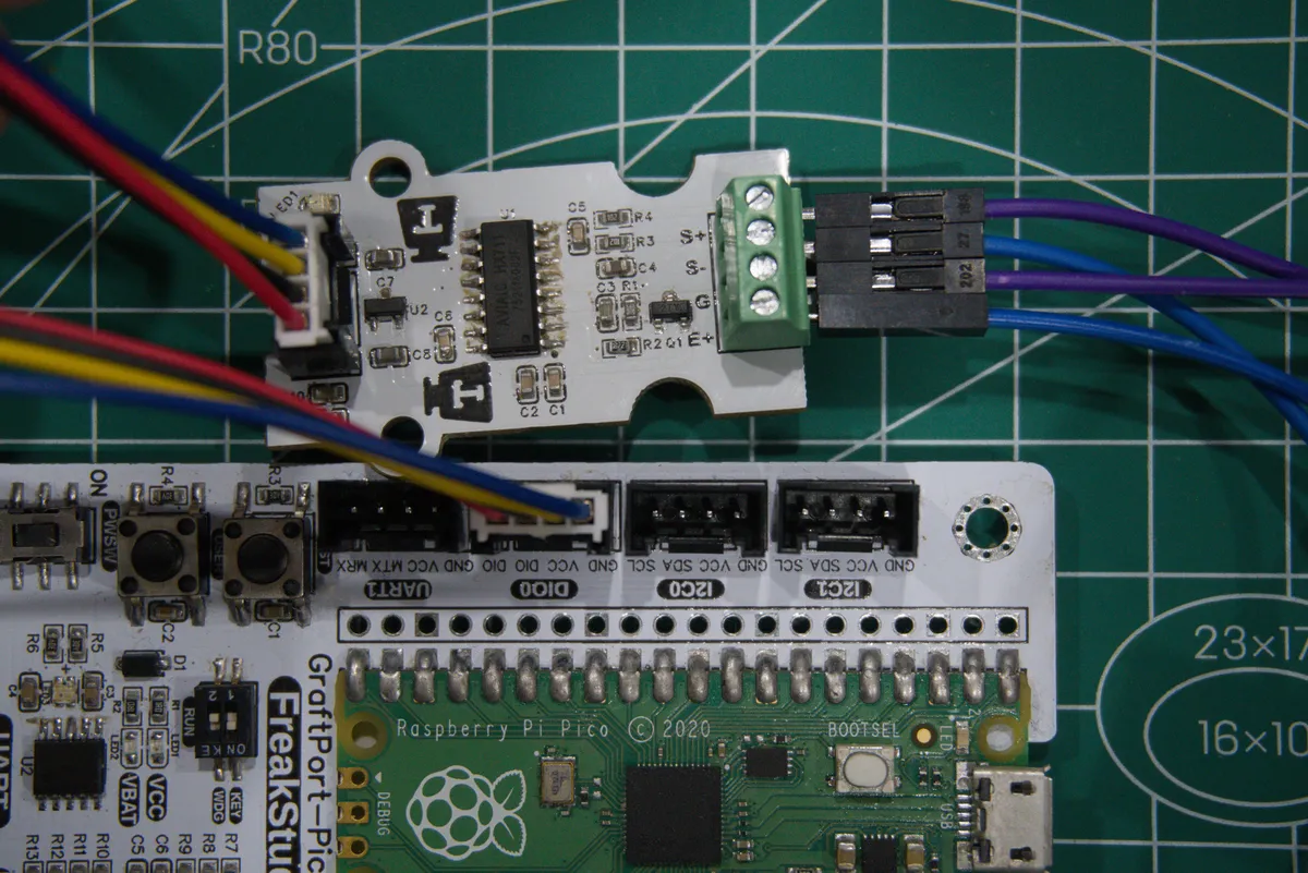
Development Board Pins | Module Pins | Description |
Pin 6 |
| HX711 sensor DATA pin |
Pin 7 |
| HX711 Sensor SCK |
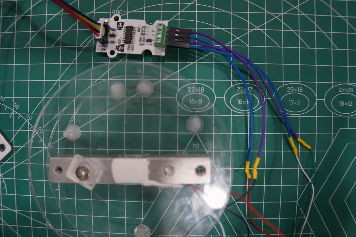
Sensor Wiring:
Support frame | Module Terminals | Description |
White |
| Positive-phase input of weighing signal |
Green |
| Weighing signal inverted input |
Red |
| Sensor power supply negative terminal |
Black |
| Sensor power supply positive terminal |
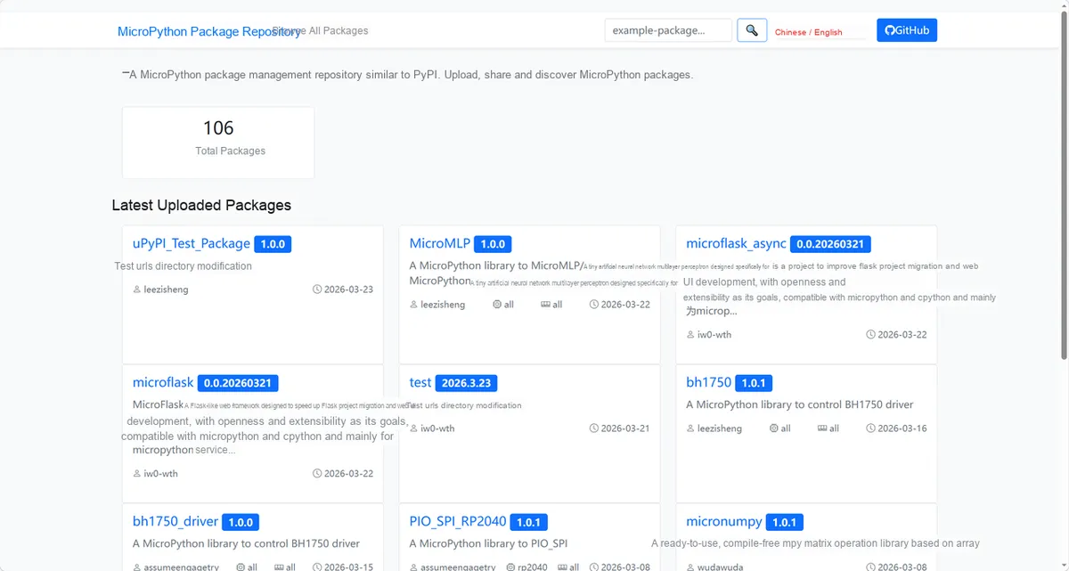
Here, we need to search for the relevant driver packages on uPyPI: https://upypi.net/zh/
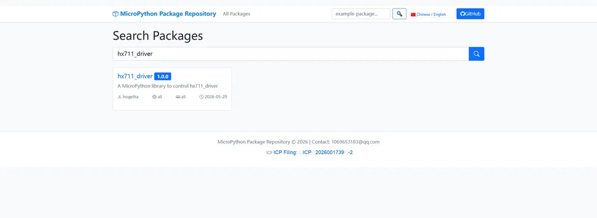
Enter hx711_driver to search, and the following will be displayed:
Click to copy the local installation command:
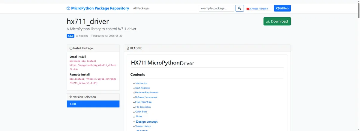
Import the module driver library code via the mip tool. Below are the usage commands for the mpremote tool:
mpremote mip install https://upypi.net/pkgs/hx711_driver/1.0.0Here, we will first briefly explain the usage of the driver library: the module just powered on has no calibration coefficients, and the values read out are raw values, so calibration is required to display the actual weight.
- First run the code above to perform tare (zeroing with no load);
- Do not place any object, record the original value:
print (hx.read_average ())→ denote it asValue 0; - Place a weight of known mass (e. g., 100g) and record the reading:
print (hx.read_average ())→ denote it asValue 1; - Calculate the calibration coefficient:
Calibration factor = (value1 - value0) / weight of the calibration weightMeanwhile, set the coefficients in the code:
hx.set_scale(校准系数)Import the MicroPython driver code for the HX711-based weighing sensor module, then copy the following main.py code into our project:
# Python env   : MicroPython v1.23.0
# -*- coding: utf-8 -*-
# @Time    : 2026/1/15 2:30 PM
# @Author  : hogeiha
# @File    : main.py
# @Description : HX711 load cell calibration and measurement program, supporting tare, calibration and real-time weight display

# ======================================== Import Modules =========================================
from hx711_gpio import HX711
from machine import Pin
import time

# ======================================== Global Variables ============================================
# Calibration weight mass, in grams
CAL_WEIGHT = 100

# ======================================== Functions ============================================

# ======================================== Custom Classes ============================================

# ======================================== Initialization configuration ===========================================
# Wait for the system to stabilize
time.sleep(3)
print("FreakStudio: HX711 sensor initialization starting")

# Define the data pin and clock pin
# 6 = DATA, 7 = SCK
pin_DATA = Pin(6, Pin.IN, pull=Pin.PULL_DOWN)
pin_SCK = Pin(7, Pin.OUT)

# Initialize the HX711 sensor
try:
    hx = HX711(pin_SCK, pin_DATA, gain=128)
    print("HX711 initialization successful")
    time.sleep(1)
except Exception as e:
    print("Sensor initialization failed:", e)
    while True:
        pass

# ========================================  Main Program  ============================================
# Perform tare operation
print("Please keep no load, starting tare...")
time.sleep(2)

# Read the average of 20 readings as the offset
offset = hx.read_average(times=20)
hx.set_offset(offset)
# Synchronize the filter baseline value
hx.filtered = offset
print("Tare completed")
print("Zero offset value:", offset)

# Calibration procedure: place the standard weight
input("Please put the standard weight and press Enter to continue...")
time.sleep(2)

# Read the average of 20 readings after loading the weight
cal_raw = hx.read_average(times=20)
net_raw = cal_raw - hx.OFFSET

print("Raw value after loading:", cal_raw)
print("Net increment:", net_raw)

# Check whether the calibration increment is too small
if abs(net_raw) < 1000:
    raise ValueError("Calibration increment too small, please check HX711 wiring, sensor connection or weight correctness")

# Calculate the conversion factor and set it
scale_factor = net_raw / CAL_WEIGHT
hx.set_scale(scale_factor)

print("Calibration completed")
print("SCALE =", scale_factor)
print("----------------------------------------")

# Synchronize the filter again to avoid drift in the first few readings right after calibration
hx.filtered = hx.read_average(times=10)

# Main loop: continuously read and display the weight
while True:
    raw_value = hx.read()
    weight = hx.get_units()
    print("Raw value: {:>10.0f} | Weight: {:>8.2f} g".format(raw_value, weight))
    time.sleep(0.2)
Burn the code, open the terminal, and the output is as follows:
Calibration Procedure:
# Calibration weight mass, in grams
CAL_WEIGHT = 100 #Change to the mass of the calibration object in grams
Example of no-load operation:
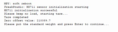
Place the calibration object after the terminal no-load calibration is completed:
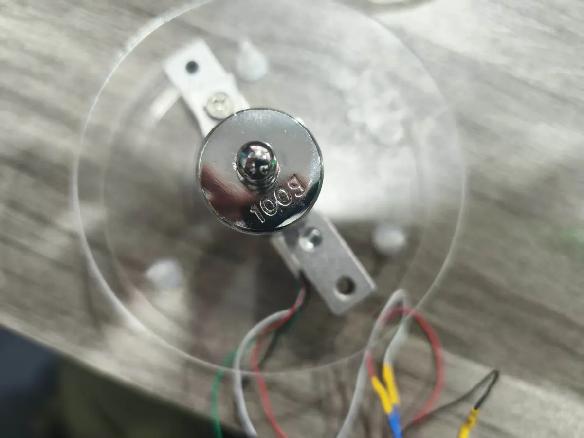
Place a 100g weight and press Enter to perform calibration:
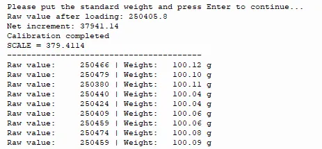
After the calibration is completed, we placed an iPhone 12 mini with a standard weight of 162g to verify the results:
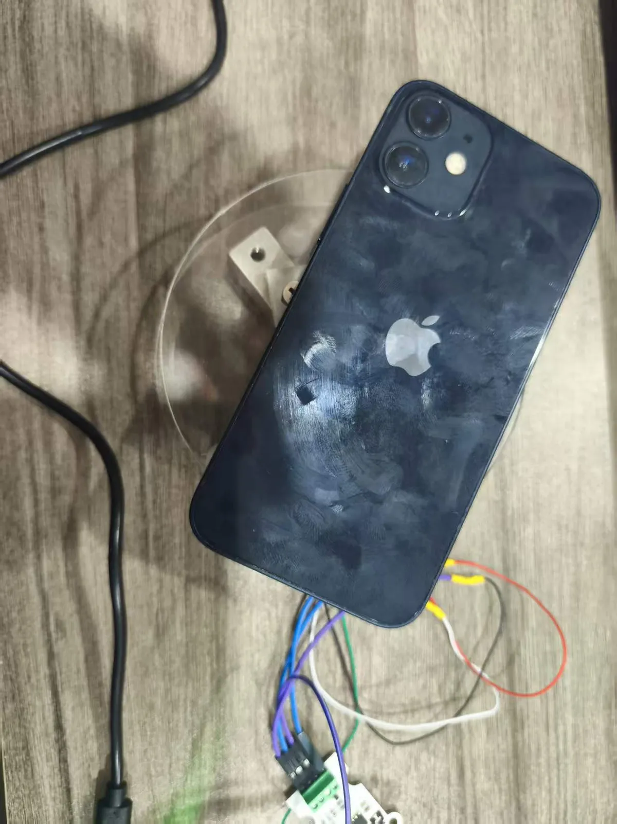
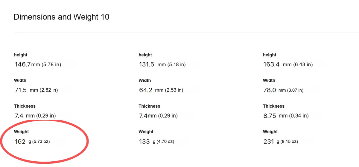
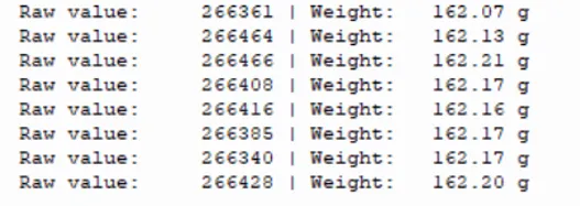
The output is 162g, which is consistent with the expectation.
Place a standard 50g weight to verify the result:
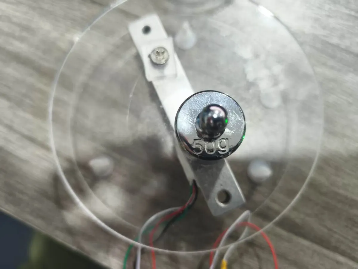
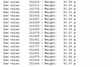
The output is 50g, which is consistent with the expectation.
IV. Drivers
hx711_driver-1.0.0.zip 11 KB
5. BOM & Recommended Alternative Parts
None.
VI. Revision History
Document Version | Date Modified | Modifier | Modify Content |
v1.0 | 2026-05-12 | Ling Gaoxing | Initialize the document |
v1.1 | 2026-06-06 | Xin Ruili | Create an open version of the document based on the internal document version v1.0. |
7. Relevant Materials
7.1 Chip Datasheet
HX711.pdf 315 KB
7.2 Unique Icons for PCB Silk Screen