Contents
- I. Module Introduction
- II. Introduction to Main Chips
- 2.1 Chip Overview
- 2.2 Pin Definition
- 2.3 Functional Block Diagram
- 2.4 Performance Parameters
- 2.5 Reference Circuit
- 2.6 Chip Configuration
- 2.7 Communication Interfaces and Related Protocols
- 2.8 PCB Routing Precautions
- III. Circuit Engineering
- 3.1 Circuit Source Engineering
- 3.2 Module Usage Instructions
- 3.3 Application Experiment
- IV. Drivers
- 5. BOM & Recommended Alternative Parts
- VI. Revision History
- 7. Relevant Materials
- 7.1 Chip Datasheet
- 7.2 Unique Icons for PCB Silk Screen
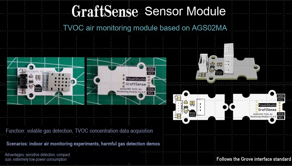
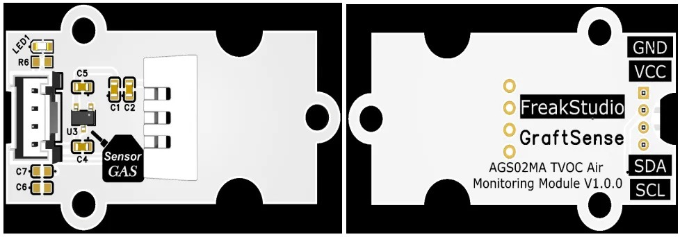
I. Module Introduction
TVOC Air Monitoring Module Based on AGS02MA, which adopts the AGS02MA MEMS gas sensor solution, can detect the concentration of total volatile organic compounds (TVOC) and directly output digital signals at the ppb level; the module is equipped with an LDO voltage regulator circuit, power filtering and indicator circuit, powered by a wide voltage range of 3.3~5.5V, communicates with the main controller via the I²C interface, featuring fast response and long-term stability, and is suitable for scenarios such as air purifiers, fresh air systems, and household air quality detectors.
II. Introduction to Main Chips
AGS02MA is a MEMS process TVOC gas sensor from Aosong Electronics. It has I2C digital output, factory calibration , 3.3-5.5V wide voltage power supply, and can detect various volatile organic compounds such as formaldehyde, ammonia, and benzene. It has the characteristics of low power consumption, high sensitivity, fast response, and long-term stability.
2.1 Chip Overview
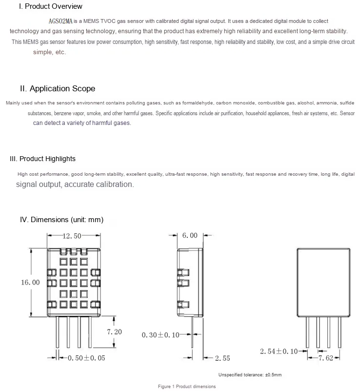
AGS02MA is a MEMS TVOC gas sensor from Aosong Electronics. It features digital signal output, low power consumption, high sensitivity, fast response and excellent stability. It can detect various harmful gases including formaldehyde, carbon monoxide and ammonia, and is suitable for devices such as air purifiers and fresh air systems. It measures 16×12.5×6mm in dimension and adopts a through-hole package.
2.2 Pin Definition
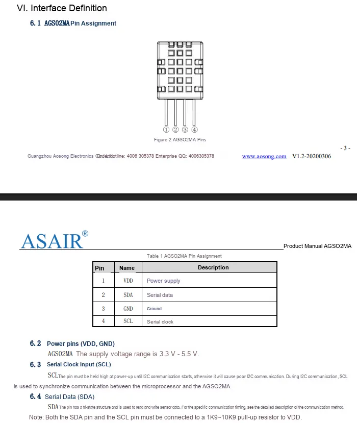
AGS02MA adopts a 4-pin DIP package: Pin 1 VDD serves as the power supply (operating voltage range: 3.3-5.5V), Pin 2 SDA acts as the I²C serial data line, Pin 3 GND is the ground pin, and Pin 4 SCL functions as the I²C serial clock line. During communication, SDA and SCL require external pull-up resistors of 1kΩ to 10kΩ connected to VDD to enable synchronous data transmission with the main controller.
2.3 Functional Block Diagram
None.
2.4 Performance Parameters
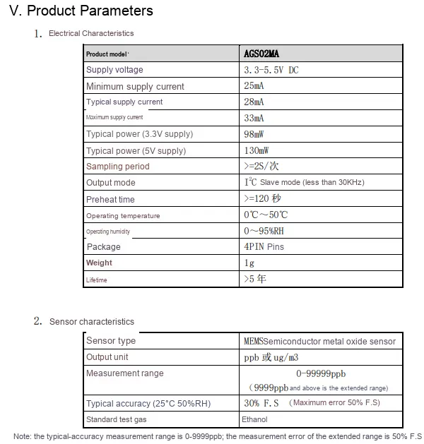
AGS02MA supports a 3.3-5.5V power supply with a typical current of 28mA; 3.3V / 5V power supply delivers typical power consumption of 98mW and 130mW respectively. It features I²C slave mode output, a sampling period of ≥2 seconds, a warm-up time of ≥120 seconds, operating temperature and humidity range of 0-50℃ and 0-95% RH, and a service life of over 5 years.In terms of sensor characteristics, as a MEMS metal oxide sensor, it outputs readings in the unit of ppb/μg/m³, with a measurement range of 0-99999 ppb (standard accuracy range: 0-9999 ppb), a typical accuracy of 30% F.S (maximum error: 50% F.S), and ethanol is used as the standard test gas.
2.5 Reference Circuit
None.
2.6 Chip Configuration
None.
2.7 Communication Interfaces and Related Protocols
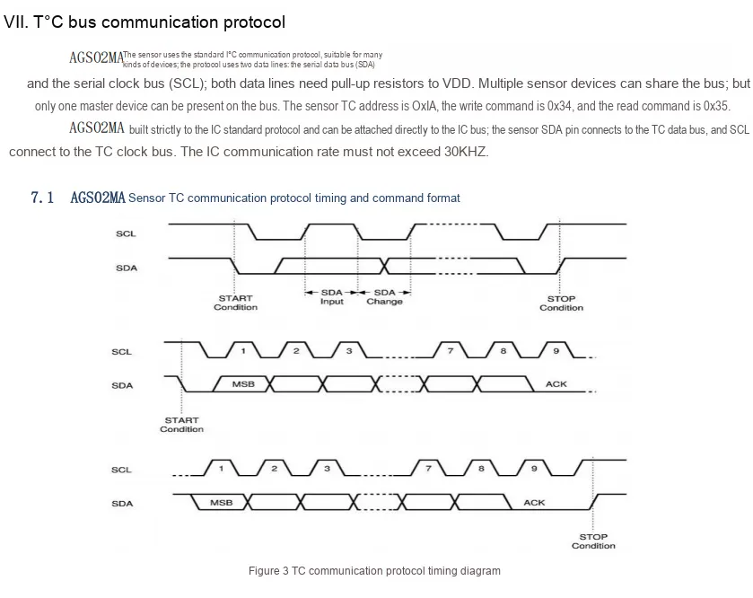
AGS02MA adopts the standard I²C Communication Protocol, with a device address of 0x1A, a write command of 0x34, a read command of 0x35, and a communication rate no higher than 30kHz; external pull-up resistors from SDA / SCL to VDD are required for communication, the timing follows the standard process of start, data transmission, acknowledge and stop, and a single host can control multiple devices.
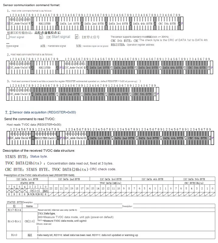
AGS02MA I²C communication complies with standard protocols and supports three formats: host write command, read command, and simplified read command. When reading TVOC data, the register address (default 0x00) must be sent first, followed by receiving the status byte, 24-bit concentration data, and CRC check byte; the status byte can identify the data mode (ppb/μg/m³) and data ready status, ensuring the accuracy and reliability of data transmission.
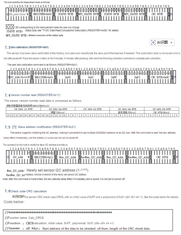
AGS02MA 's I²C command and check mechanism supports functions including modifying the measurement mode, zero point calibration (the command shall be sent after power-on for 5 minutes in clean air), reading the version number, and modifying the I²C address (the new address is saved after power-off), and also provides the CRC8 check algorithm with the initial value 0xFF and the polynomial 0x31 to ensure the reliability of communication data.
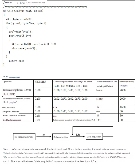
AGS02MA CRC8 checksum algorithm code and complete commands, including instructions for setting the TVOC measurement mode (ppb/μg/m³), Data Acquisition, zero point calibration, version reading and modifying the I²C address. It specifies the register address, parameters, returned data volume and processing time of each instruction, and marks key timing requirements such as a 30ms interval after a write command, a 2s wait after mode setting, and a Data Acquisition interval of no less than 1.5s to ensure stable communication.
2.8 PCB Routing Precautions
None.
III. Circuit Engineering
3.1 Circuit Source Engineering
To obtain the source code of the circuit, please follow the official account [Freak Embedded]
3.2 Module Usage Instructions
The schematic diagram of this module is shown below:
SCH_Schematic1_AGS02MA-Based TVOC Air Monitoring Module_v1.0.0_2026-05-11.pdf 2.1 MB
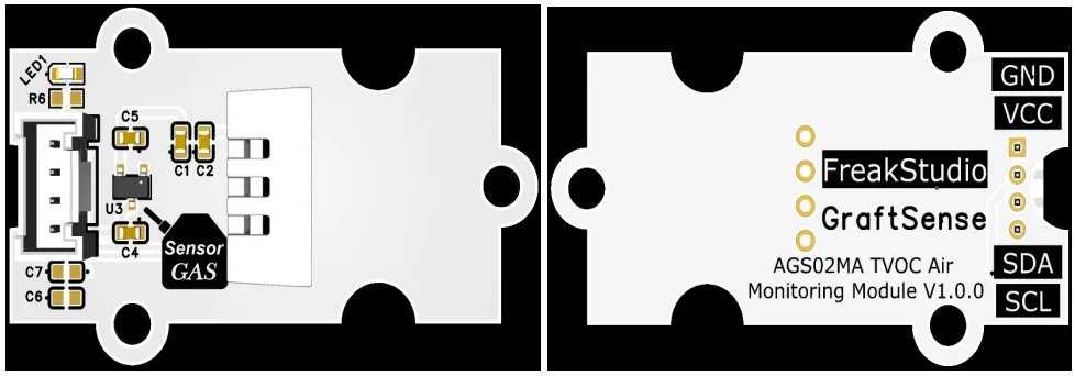
This module provides an IIC communication interface: it supports standard I2C communication baud rates, is compatible with a wide voltage level range of 3.3~5.5V, and can stably transmit the ppb-level AGS02MA -collected TVOC concentration digital signal. It is suitable for scenarios such as air purifiers, fresh air systems, and household air quality detectors, providing the system with reliable data interaction capability for volatile organic compound concentration.
3.3 Application Experiment
Here, we use the GraftPort-RP2040 development board for testing, and the AGS02MA-based TVOC air monitoring module uses the I2C interface to communicate with the main controller.
Here, we first use the HY2.0-4P cable to connect the module to the GraftPort-RP2040 development board's I2C0 interface:
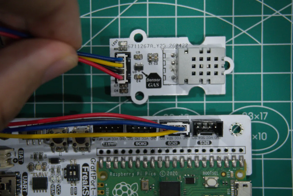
Development Board Pins | Module Pins | Description |
Pin 4 |
|
|
Pin 5 |
|
|
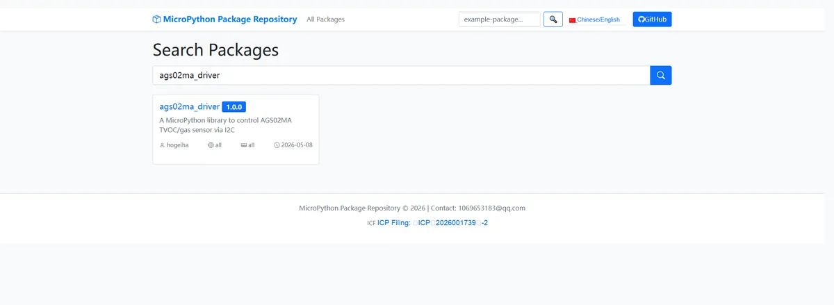
Here, we need to search for the relevant driver packages on uPyPI: https://upypi.net/zh/
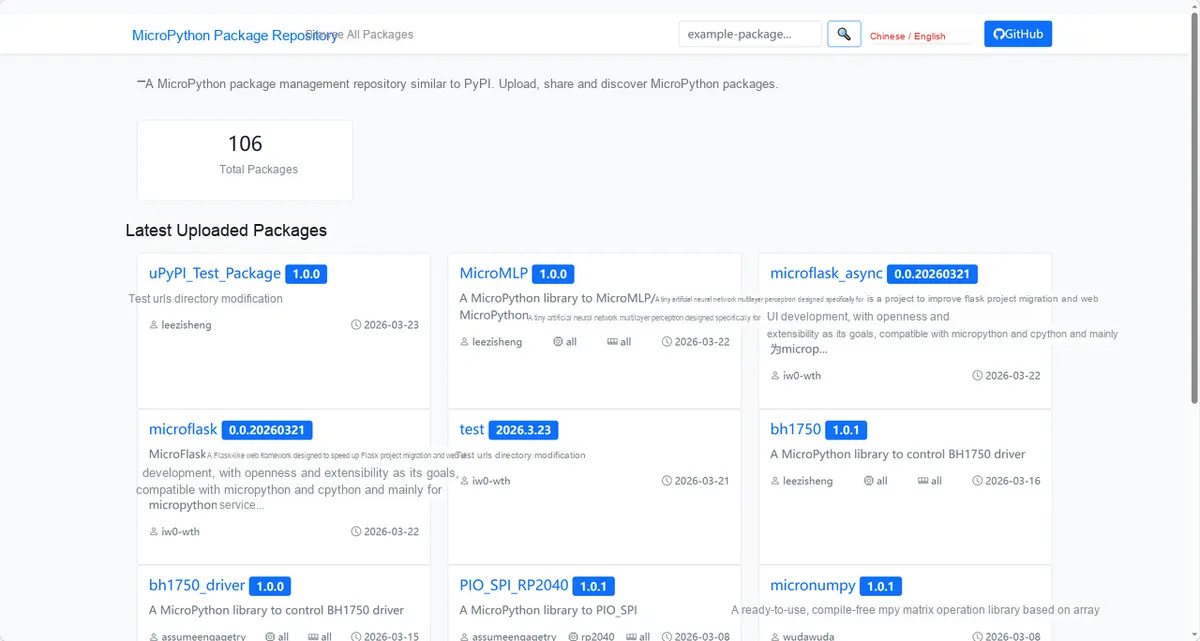
Enter ags02ma_driver to search, and the following will be displayed:
Click to copy the local installation command:
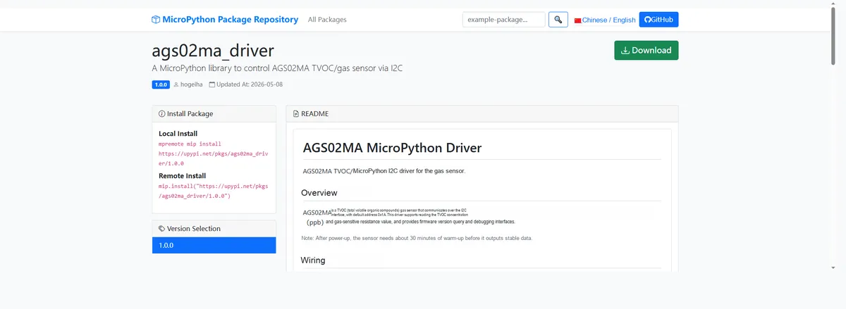
Import the module driver library code via the mip tool. Below are the usage commands for the mpremote tool:
mpremote mip install https://upypi.net/pkgs/ags02ma_driver/1.0.0Import the TVOC air monitoring module based on AGS02MA - MicroPython driver code, then copy the following main.py code into our project:
# Python env   : MicroPython v1.23.0
# -*- coding: utf-8 -*-
# @Time    : 2026/04/22 14:15
# @Author  : hogeiha
# @File    : main.py
# @Description : AGS02MA gas sensor reading example


# ======================================== Import Modules =========================================

import machine
import time
from ags02ma import AGS02MA


# ======================================== Global Variables ============================================

# I2C data pin number
I2C_SDA_PIN = 4

# I2C clock pin number
I2C_SCL_PIN = 5

# AGS02MA requires low-speed I2C communication
I2C_FREQ = 20000

# Sensor reading interval (seconds)
READ_INTERVAL = 10

# Sensor power-on warm-up wait time (seconds)
WARMUP_SECONDS = 120


# ======================================== Functions ============================================


# ======================================== Custom Classes ============================================


# ======================================== Initialization configuration ===========================================

# Wait for the system and sensor power to stabilize
time.sleep(3)

# Print the program function prompt
print("FreakStudio: AGS02MA gas sensor")

# Initialize the software I2C bus
i2c = machine.SoftI2C(
    scl=machine.Pin(I2C_SCL_PIN),
    sda=machine.Pin(I2C_SDA_PIN),
    freq=I2C_FREQ,
)

# Scan for devices on the I2C bus
devices = i2c.scan()

# Print I2C device scan result
print("Devices: {}".format(devices))

# Create AGS02MA sensor object
ags = AGS02MA(i2c)

# Read firmware version
firmware_version = ags.firmware_version() & 0x0000FF

# Print firmware version
print("Firmware version: {}".format(firmware_version))

# Print sensor warm-up notice
print("Warmup for {} seconds".format(WARMUP_SECONDS))


# ========================================  Main Program  ============================================

# Continuously read AGS02MA sensor data
while True:

    # Catch single-read exceptions to keep the example program from exiting
    try:

        # Read TVOC concentration value
        tvoc = ags.TVOC

        # Print TVOC concentration value
        print("TVOC: {}".format(tvoc))

    # Print English error when reading TVOC fails
    except RuntimeError as exc:
        print("TVOC read failed: {}".format(exc))

        # Print raw TVOC debug data
        print("TVOC raw: {}".format(ags.debug_read_raw(0x00)))

    # Catch single-read exceptions to keep the example program from exiting
    try:

        # Read gas sensor resistance value
        gas_resistance = ags.gas_resistance

        # Print gas sensor resistance value
        print("Gas resistance: {}".format(gas_resistance))

    # Print English error when reading gas sensor resistance fails
    except RuntimeError as exc:
        print("Gas resistance read failed: {}".format(exc))

        # Print raw gas sensor resistance debug data
        print("Gas resistance raw: {}".format(ags.debug_read_raw(0x20)))

    # Wait for the next read
    time.sleep(READ_INTERVAL)
Burn the code, open the terminal, and the output is as follows:
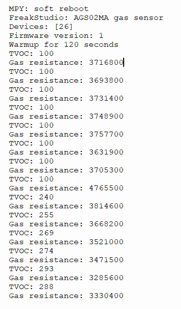
The AGS02MA gas sensor completed 120 seconds of preheating; in the initial stage, the TVOC reading stabilized at 100, and the gas resistance stabilized at approximately 3.7 MΩ.
IV. Drivers
5. BOM & Recommended Alternative Parts
None.
VI. Revision History
Document Version | Date Modified | Modifier | Modify Content |
v1.0 | 2026-05-11 | Ling Gaoxing | Initialize the document |
v1.1 | 2026-06-06 | Xin Ruili | Create an open version of the document based on the internal document version v1.0. |
7. Relevant Materials
7.1 Chip Datasheet
AGS02MA.pdf 713 KB
7.2 Unique Icons for PCB Silk Screen