Contents
- I. Module Introduction
- II. Introduction to Main Chips
- 2.1 Chip Overview
- 2.2 Pin Definition
- 2.3 Functional Block Diagram
- 2.4 Performance Parameters
- 2.5 Reference Circuit
- 2.6 Chip Configuration
- 2.7 Communication Interfaces and Related Protocols
- 2.8 PCB Routing Precautions
- III. Circuit Engineering
- 3.1 Circuit Source Engineering
- 3.2 Module Usage Instructions
- 3.3 Application Experiment
- IV. Drivers
- 5. BOM & Recommended Alternative Parts
- VI. Revision History
- VII. Relevant Materials
- 7.1 Chip Datasheet
- 7.2 Unique Icons for PCB Silk Screen
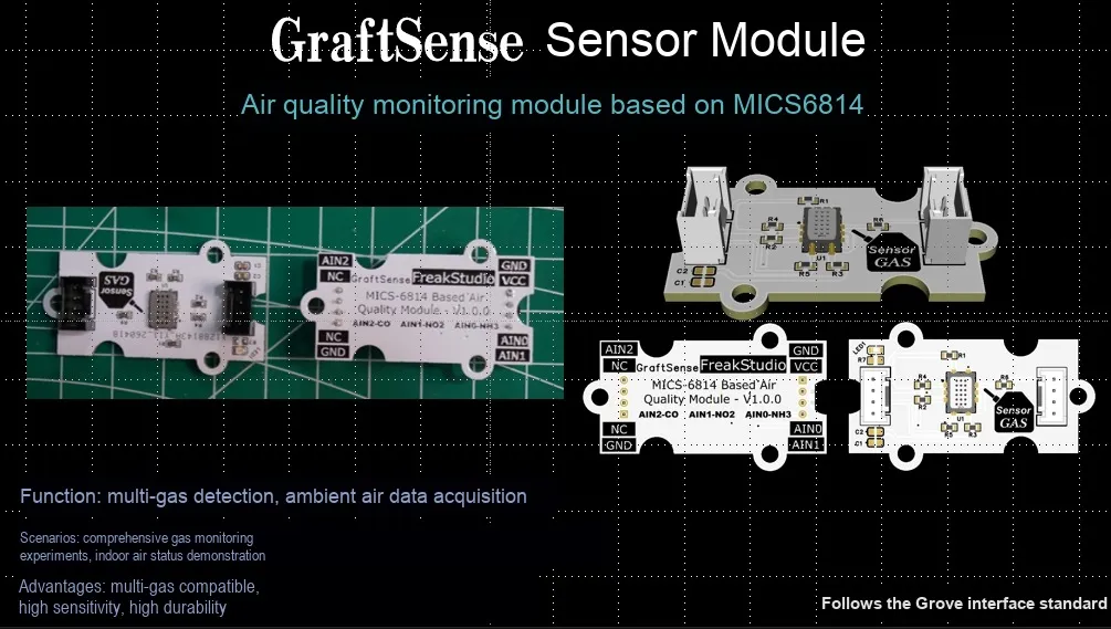
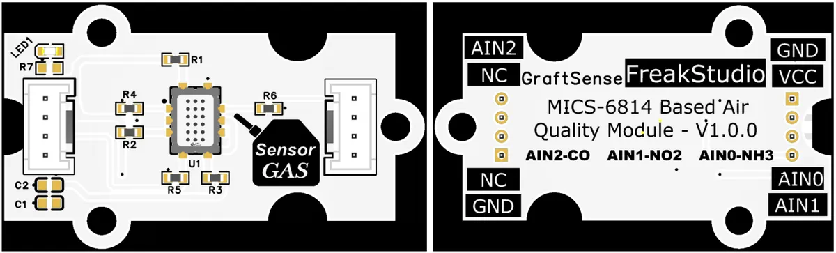
I. Module Introduction
MICS-6814-based air quality monitoring module that adopts the MICS-6814 multi-gas sensor solution, capable of simultaneously detecting the concentrations of carbon monoxide (CO), nitrogen dioxide (NO₂) and ammonia (NH₃), and outputs signals via the analog interfaces AIN0, AIN1 and AIN2; the module is equipped with power filtering and indicator light circuits, operates on 3.3V/5V power supply, features a simple peripheral circuit, and is applicable to scenarios such as indoor air quality monitoring, environmental detection, and industrial gas monitoring.
II. Introduction to Main Chips
MICS-6814 is a compact SGX Sensortech compact MEMS metal oxide gas sensor launched by the company, which integrates three independent sensing units, can simultaneously detect multiple gases such as CO, NO₂ and NH₃, features analog output and a small size (5×7×1.55mm), and is suitable for air quality monitoring and industrial gas detection.
2.1 Chip Overview
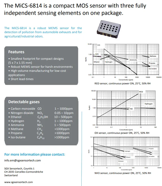
MICS-6814 is a compact SGX Sensortech MEMS gas sensor launched by, which incorporates three independent sensing units and can simultaneously detect a variety of gases including CO, NO₂, and NH₃. Measuring only 5×7×1.55mm, it is designed for harsh environments and suitable for scenarios such as automotive exhaust detection and industrial/agricultural odor monitoring.
2.2 Pin Definition
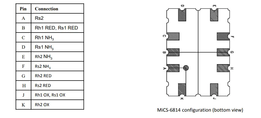
MICS-6814 has 10 pins corresponding to the heating resistors (Rh) and sensing resistors (Rs) of the three sensing units (RED, NH₃, OX) respectively: RED unit (for detecting CO and other gases) occupies pins B, G, H, A;NH₃ unit (for detecting ammonia and other gases) occupies pins C, D, E, F;OX unit (for detecting NO₂ and other gases) occupies pins J, K. For each unit, Rh serves as the heating terminal and Rs serves as the signal terminal, and an external circuit is required to realize voltage division acquisition of gas concentration.
2.3 Functional Block Diagram
None.
2.4 Performance Parameters
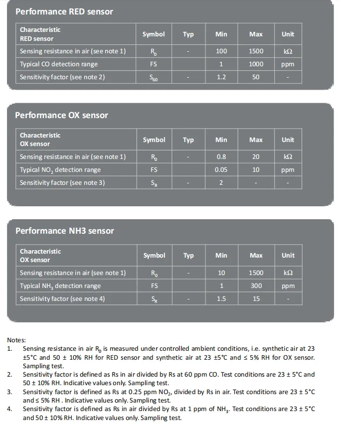
The above is the performance parameter table for the three sensing units of MICS-6814: RED unit (for CO detection): resistance in air is 100-1500kΩ, detection range is 1-1000ppm;OX unit (for NO₂ detection): resistance in air is 0.8-20kΩ, detection range is 0.05-10ppm;NH₃ unit (for ammonia detection): resistance in air is 10-1500kΩ, detection range is 1-300ppm, and sensitivity factors under different conditions are provided for each unit.
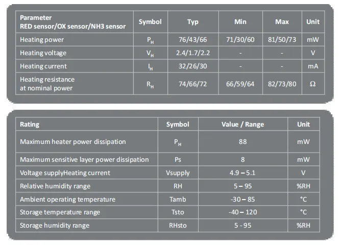
MICS-6814 typical heating voltage of the three sensing units are 2.4V , 1.7V , 2.2V , corresponding to the heating power 76mW, 43mW, 66mW; while specifying its working conditions, power supply voltage 4.9 - 5.1V , operating temperature - 30~ 85 ℃, humidity 5-95% RH, storage temperature - 40~ 120 ℃, and defines the maximum heating power and power consumption of the sensitive layer.
2.5 Reference Circuit
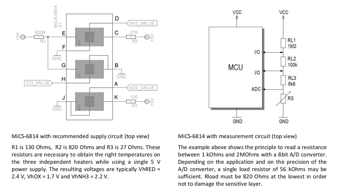
The left-side circuit steps down voltage for the three heating units of R1, R2, and R3 to MICS-6814, and under a single 5V power supply, it supplies heating voltages of approximately RED, OX, and NH₃ to the respective channels, i. e., around 2.4V, 1.7V, and 2.2V, to maintain the operating temperature of the sensing unit. The right-side circuit adopts a voltage division method, using the MCU 's ADC to sample the voltage across the sensing resistor RS, thereby converting the resistance variation caused by changes in gas concentration into a readable digital signal, enabling the detection of gases including CO, NO₂, and NH₃.
2.6 Chip Configuration
None.
2.7 Communication Interfaces and Related Protocols
None.
2.8 PCB Routing Precautions
None.
III. Circuit Engineering
3.1 Circuit Source Engineering
To obtain the circuit source project, please follow the official account [Freak Embedded]
3.2 Module Usage Instructions
The schematic diagram of this module is shown below:
SCH_Schematic1_Air Quality Monitoring Module Based on MICS6814_v1.0.0_2026-05-11.pdf 2.1 MB
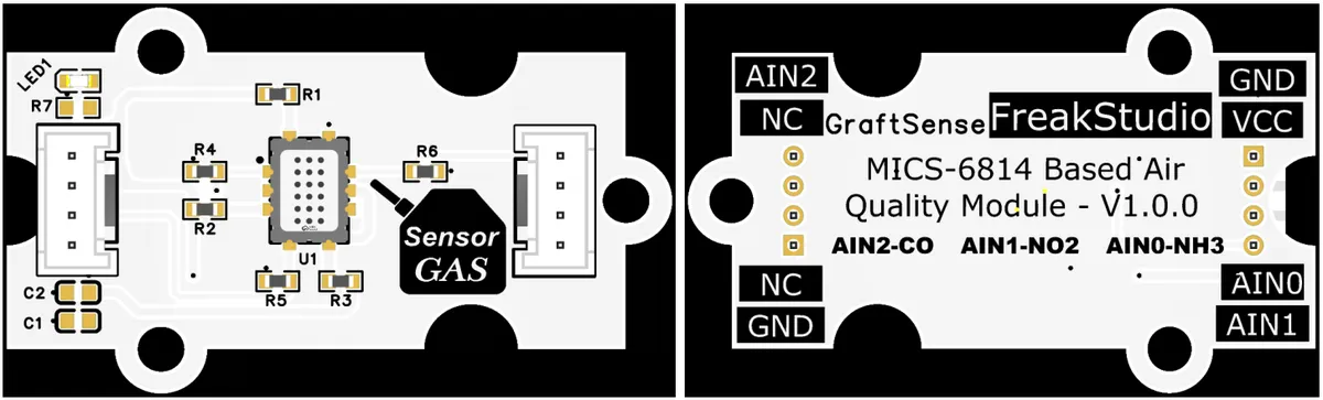
This module provides analog output AIN0 - AIN2 : where AIN0 outputs the analog voltage signal corresponding to the concentration of ammonia ( NH ), AIN1 outputs the analog voltage signal corresponding to the concentration of nitrogen dioxide ( NO2 ), AIN2 outputs the analog voltage signal corresponding to the concentration of carbon monoxide ( CO ), which can be directly connected to the main control ADC port to read the voltage value and convert the gas concentration, suitable for indoor air quality monitoring, environmental detection, smart home and other multi-gas detection scenarios.
3.3 Application Experiment
Here, we use the GraftPort-RP2040 development board for testing, and the MICS6814-based air quality monitoring module communicates with the main controller via the AIN interface.
Here, we first use the HY2.0-4P cable to connect the module to the GraftPort-RP2040 development board's AIN0 AIN1 interfaces:
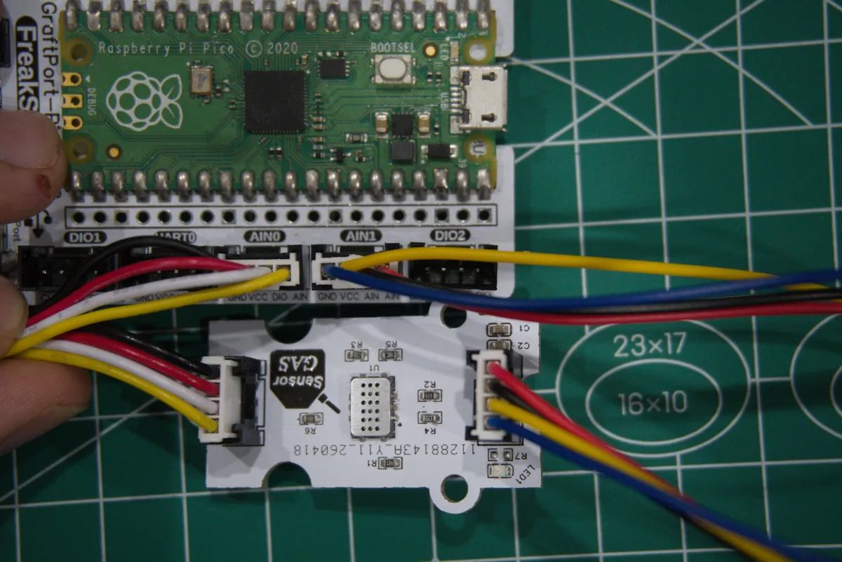
development board pins | Module Pins | Description |
Pin 26 |
|
|
Pin 19 |
| - |
Pin 28 |
|
|
Pin 27 |
|
|
Here, we need to search for the relevant driver packages on uPyPI: https://upypi.net/zh/

Enter mics6814_driver to search, and the following will be displayed:

Click to copy the local installation command:
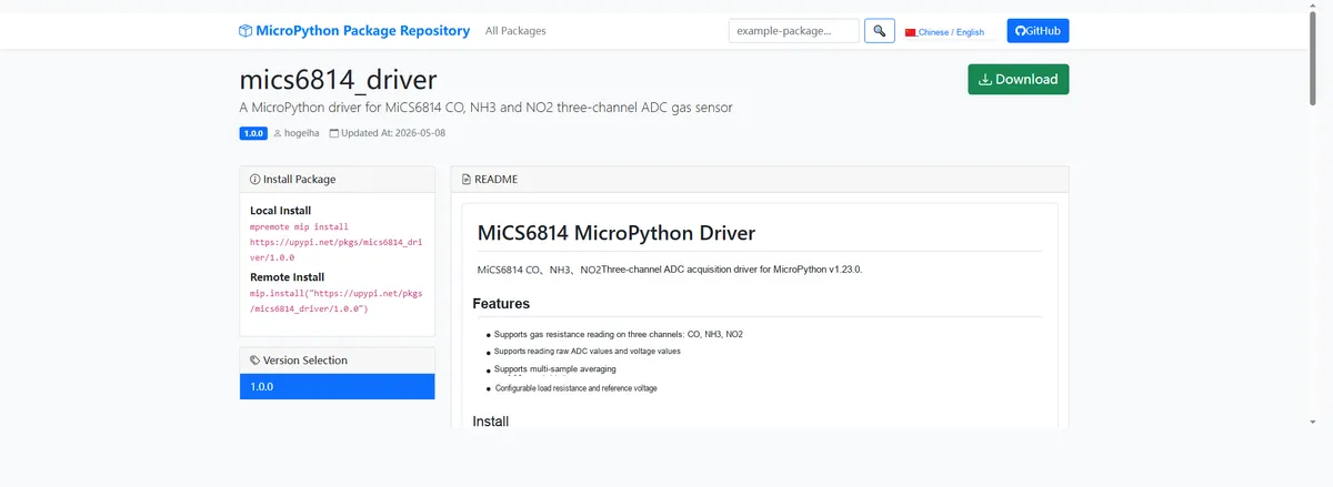
Import the module driver library code via the mip tool. Below are the usage commands for the mpremote tool:
mpremote mip install https://upypi.net/pkgs/mics6814_driver/1.0.0Import the MicroPython driver code for the MICS6814-based air quality monitoring module, then copy the following main.py code into our project:
# Python env   : MicroPython v1.23.0
# -*- coding: utf-8 -*-
# @Time    : 2026/4/21 PM
# @Author  : hogeiha
# @File    : main.py
# @Description : MiCS6814 CO, NH3, NO2 three-channel ADC reading example

# ======================================== Import Modules =========================================

import time
from mics6814 import MICS6814

# ======================================== Global Variables ============================================

# CO channel is connected to Pico GPIO26
CO_PIN = 26

# NH3 channel is connected to Pico GPIO27
NH3_PIN = 27

# NO2 channel is connected to Pico GPIO28
NO2_PIN = 28

# ======================================== Functions ============================================

# ======================================== Custom Classes ============================================

# ======================================== Initialization configuration ===========================================

time.sleep(3)
print("FreakStudio: MICS6814 CO NH3 NO2 ADC sensor")

# Create the MiCS6814 three-channel ADC acquisition object
gas = MICS6814(CO_PIN, NH3_PIN, NO2_PIN)

# ========================================  Main Program  ============================================

try:
    while True:
        # Read the resistance, voltage and raw ADC values of the CO, NH3 and NO2 channels
        readings = gas.read_all()

        # Print the sensor readings
        print(readings)

        # Read the sensor once per second
        time.sleep(1)
except KeyboardInterrupt:
    pass
Burn the code, open the terminal, and the output is as follows:
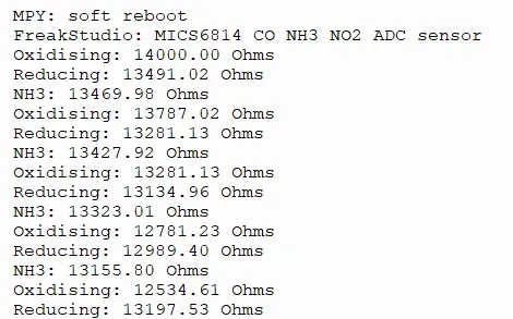
The MICS6814 gas sensor works properly and can stably output the resistance values corresponding to oxidizing gases, reducing gases and NH3; its readings fluctuate slightly with the environment and feature stable response.
IV. Drivers
mics6814_driver-1.0.0.zip 7 KB
5. BOM & Recommended Alternative Parts
None.
VI. Revision History
Document Version | Date of Revision | Modifier | Modify Content |
v1.0 | 2026-05-11 | Zero High-Luck | Initialize the document |
v1.1 | 2026-06-06 | Xin Ruili | Create an open version of the document based on the internal document version v1.0. |
VII. Relevant Materials
7.1 Chip Datasheet
MICS6814.pdf 373 KB
7.2 Unique Icons for PCB Silk Screen