Contents
- I. Module Introduction
- II. Introduction to Main Chips
- 2.1 Chip Overview
- 2.2 Pin Definition
- 2.3 Functional Block Diagram
- 2.4 Performance Parameters
- 2.5 Reference Circuit
- 2.6 Chip Configuration
- 2.7 Communication Interfaces and Related Protocols
- 2.8 PCB Routing Notes
- III. Circuit Engineering
- 3.1 Circuit Source Engineering
- 3.2 Module Usage Instructions
- 3.3 Application Experiment
- IV. Drivers
- 5. BOM & Recommended Alternative Parts
- 6. Revision History
- VII. Relevant Materials
- 7.1 Chip Datasheet
- 7.2 Unique Icons for PCB Silk Screen
I. Module Introduction
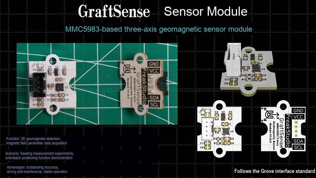
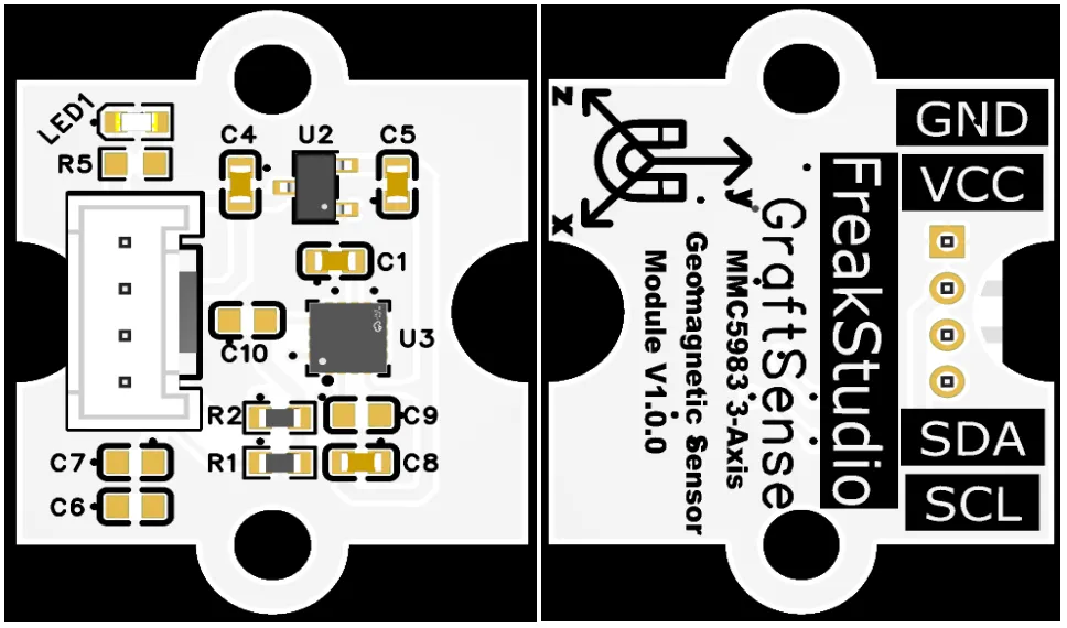
Triaxial geomagnetic sensor module based on MMC5983, which adopts the automotive-grade triaxial MMC5983 from MEMSIC Semiconductor AMR geomagnetic sensor solution, can measure the magnetic field strength of X / Y / Z three axes with high precision and output 18-bit digital signal, realizing the electronic compass function with a heading accuracy of ±0.5°;The module is equipped with LDO voltage regulator circuits, power filtering and indicator light circuits, operates on 3.3V power supply and supports I²C and high-speed SPI dual-interface communication. It features built-in automatic degaussing and temperature drift compensation, supports wide-temperature operation with low power consumption, and is suitable for automotive devices, drones, industrial navigation and various high-precision magnetic field detection scenarios.
II. Introduction to Main Chips
MMC5983 is a high-performance three-axis AMR magnetic sensor launched by MEMSIC, which is AEC-Q100 qualified (automotive grade), features a ±8G measurement range, 18-bit resolution, integrated AEC-Q100 I2C / SPI interface and signal processing, adopts LGA-16 package, delivers low power consumption, and is suitable for applications such as electronic compass, navigation and automotive.
2.1 Chip Overview
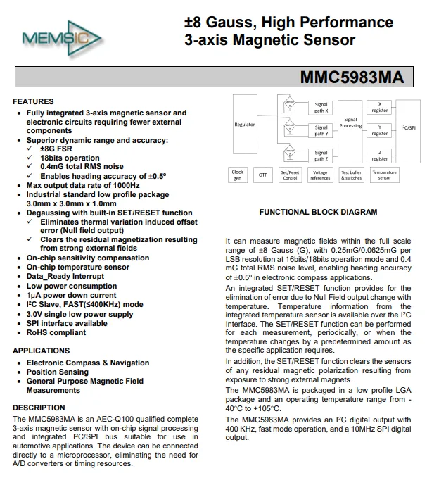
MMC5983MA 3-axis magnetic sensor is an automotive-grade (AEC-Q100) integrated solution, featuring a ±8G measurement range, 18-bit resolution, 0.4mG noise, ±0.5° heading accuracy, a maximum output rate of 1kHz, built-in SET / RESET degaussing function, temperature compensation and temperature sensor, supporting I²C (400kHz)/ SPI (10MHz) interfaces, low power consumption, and is packaged in a 3.0×3.0×1.0mm LGA package, suitable for electronic compass, navigation and automotive applications.
2.2 Pin Definition
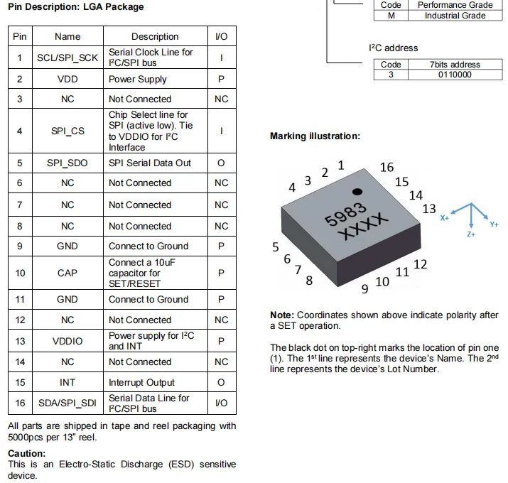
MMC5983MA LGA package pins: Pin 1 is the common clock line for I²C / SPI, Pin 16 is the common data line for I²C / SPI, Pin 4 is the SPI chip select (must be pulled high in I²C mode), Pin 5 is the SPI data output; Pin 2 VDD is the main power supply, Pin 13 VDDIO is the interface power supply, Pins 9/11 are ground, Pin 10 must be connected to a 10μF capacitor for the SET / RESET function, Pin 15 is the interrupt output, and the remaining pins are no connects.
2.3 Functional Block Diagram
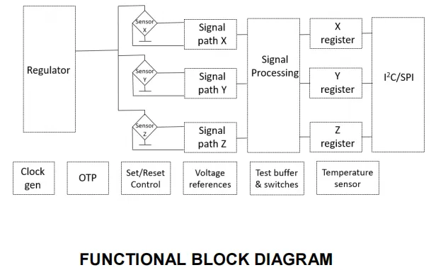
MMC5983MA is powered by an internal voltage regulator to drive the X / Y / Z three-axis magnetic sensor to acquire magnetic field signals, which are amplified and processed via respective signal paths before being sent to the signal processing unit. Meanwhile, in conjunction with modules including the on-chip clock generator, OTP calibration data, SET / RESET control, voltage reference and temperature sensor, it completes signal compensation and correction. Finally, the processed three-axis data is stored in registers and output to the main controller via the I²C or SPI interface.
2.4 Performance Parameters
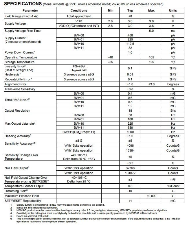
MMC5983MA at 25℃, VDD = 3.0V, has a magnetic field range of ±8G, an operating voltage of 2.8-3.6V, power consumption varying with output rate, ranging from a minimum of 1μA to a maximum of 450μA; it features 18-bit resolution, low noise (minimum 0.4mG RMS) and ±1.0° heading accuracy, and also provides key indicators such as linear error, repeatability error, temperature drift, as well as a wide temperature Scope of Work of -40~105℃.
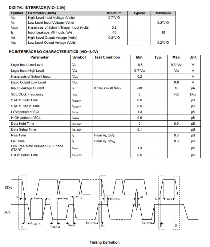
MMC5983MA features a digital interface and I²C timing parameters. The above diagram illustrates the general electrical characteristics such as high/low logic levels, hysteresis, and leakage current under the condition of VIO = 3.0V, and specifies the timing parameters of the I²C interface including the maximum clock frequency of 400kHz, the high/low level periods of SCL, setup/hold time for start/repeated start/stop conditions, data setup/hold time, and bus idle time.
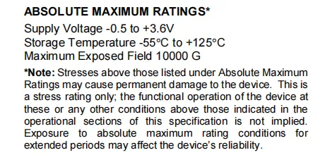
MMC5983MA has an absolute maximum rated supply voltage range of -0.5 to + 3.6 V, a storage temperature range of -55°C to + 125°C, and a maximum tolerable external magnetic field strength of 10000 G; it is emphasized that exceeding these limits may cause permanent damage, and long-term exposure to extreme conditions will also affect the device reliability.
2.5 Reference Circuit
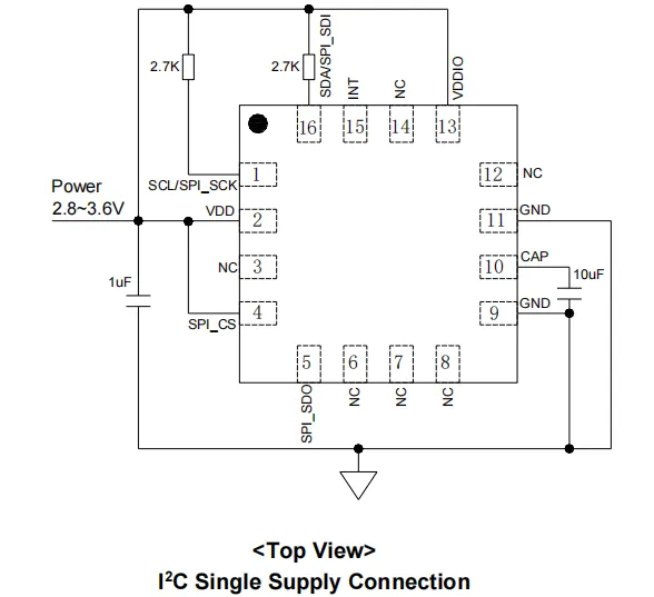
MMC5983MA has its VDD and VDDIO commonly powered by a 2.8~3.6V power supply, with a 1μF decoupling capacitor connected to the power terminal for filtering; pin 1 SCL and pin 16 SDA realize I²C bus level matching via 2.7kΩ pull-up resistors;Pin 4 SPI_CS is connected to a high power level to select the I²C mode; Pin 10 CAP is connected to a 10μF capacitor for the SET / RESET degaussing function; pins 9 and 11 are connected to ground, and the remaining floating pins are left unconnected, which realizes the basic power supply and I²C communication configuration of the sensor.
2.6 Chip Configuration
None.
2.7 Communication Interfaces and Related Protocols
2.7.1 I2C Communication
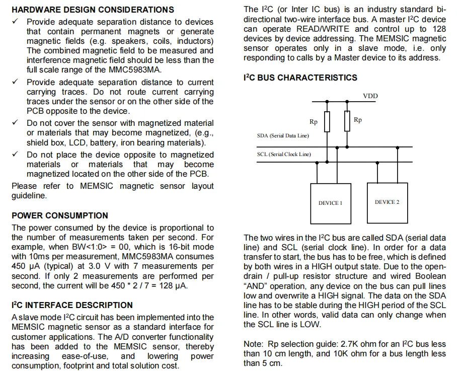
MMC5983MA works in I ² C slave mode, communicates with the host through SDA / SCL two wires, the bus needs to be connected to the pull-up resistor (such as 2.7kΩ), and the data transmission follows the timing rules of SDA stable when SCL is high and changing when it is low, supporting standard I ² C reading and writing and device addressing.
2.7.2 Registers
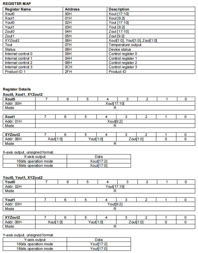
MMC5983MA defines its register mapping and data output format, lists the address and function of each register, in which the three-axis magnetic field data are stored in the Xout0 / 1, Yout0 / 1, and Zout0 / 1 registers respectively; the lower 2 bits of each axis are supplemented via the XYZout2 register, which supports both 16-bit and 18-bit data formats, and the chip also integrates temperature output, device status, control registers and the product ID register.
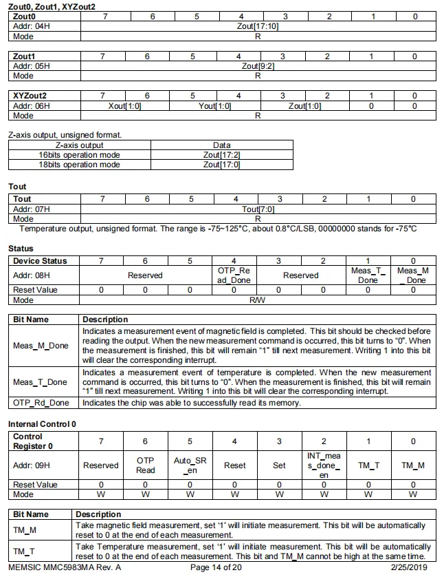
MMC5983MA registers include bit definitions and functional descriptions for: Z-axis magnetic field data (Zout0 / 1 and XYZout2), temperature data (Tout), device status register (with magnetic field/temperature measurement completion flags and OTP read status), and internal control register 0 (configurable for OTP read, automatic SET / RESET, measurement trigger, interrupt enable and other functions).
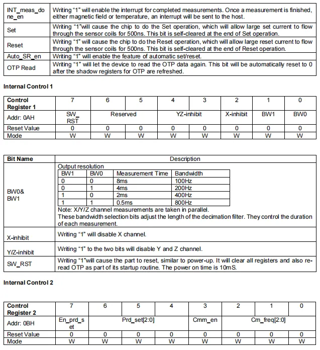
MMC5983MA has internal control registers: Internal Control 0 configures measurement completion interrupt, manual SET / RESET degaussing, automatic degaussing and OTP re-read functions;Internal Control 1 supports configuration of bandwidth (100Hz~800Hz), channel enable (X / Y / Z axis can be selectively disabled) and software reset;Internal Control 2 contains advanced configuration bits such as period setting, common-mode rejection and clock frequency.
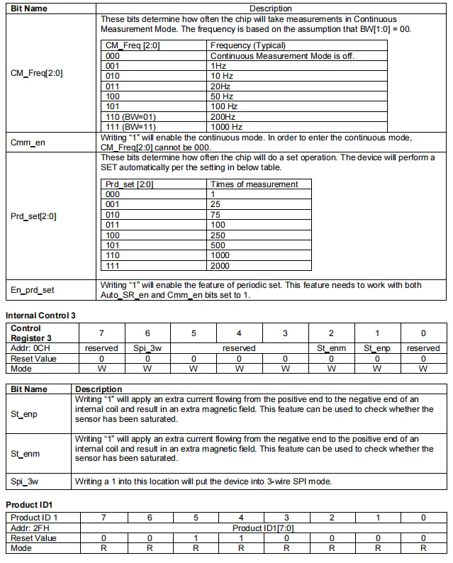
MMC5983MA has internal control registers and product ID;Internal Control 2 is used to configure the continuous measurement mode (set the sampling rate from 1 to 1000Hz via CM_Freq), automatic SET cycle (Prd_set) and cycle SET enable;Internal Control 3 supports 3-wire SPI mode and positive/negative self-test configuration;Product ID 1 register stores chip identification information, which can be used to verify the device model.
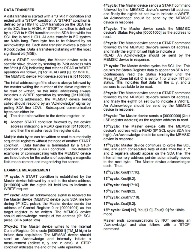
MMC5983MA ’s I²C data transmission process: taking magnetic measurement as an example, the master initiates communication via START / STOP conditions. First, it sends the device address and register address via a write command, then writes to the control register to trigger the measurement; after that, it reads the status register via a read command, and after confirming the measurement is completed, continuously reads the three-axis magnetic field data — the address pointer will automatically increment — and finally terminates the communication with a no-acknowledgment + STOP.
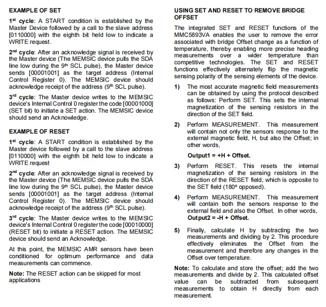
MMC5983MA features a SET / RESET function: the host triggers the SET / RESET operation by writing a command to the internal control register 0 via I²C, which can reverse the magnetic polarity of the sensor. Then, by subtracting the outputs measured in the SET and RESET states, the bridge offset and temperature drift can be eliminated, thus improving measurement accuracy and heading stability.
2.8 PCB Routing Notes
None.
III. Circuit Engineering
3.1 Circuit Source Engineering
To obtain the source code of the circuit, please follow the official account [Freak Embedded]
3.2 Module Usage Instructions
The schematic diagram of this module is shown below:
SCH_Schematic1_MMC5983-Based 3-Axis Geomagnetic Sensor Module_v1.0.0_2026-05-12.pdf 2.1 MB
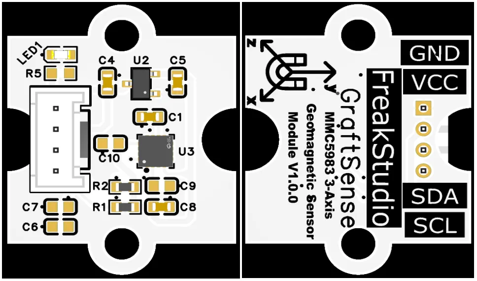
This module provides a IIC communication interface: it supports standard I2C communication rates, is compatible with 3.3V level, and can stably transmit the 18-bit digital signals of three-axis (X / Y / Z) magnetic field intensity collected by the MMC5983. It is applicable to vehicle-mounted equipment, drones, industrial navigation and various high-precision magnetic field detection scenarios, providing the system with reliable automotive-grade high-precision electronic compass and geomagnetic sensing data interaction capabilities.
3.3 Application Experiment
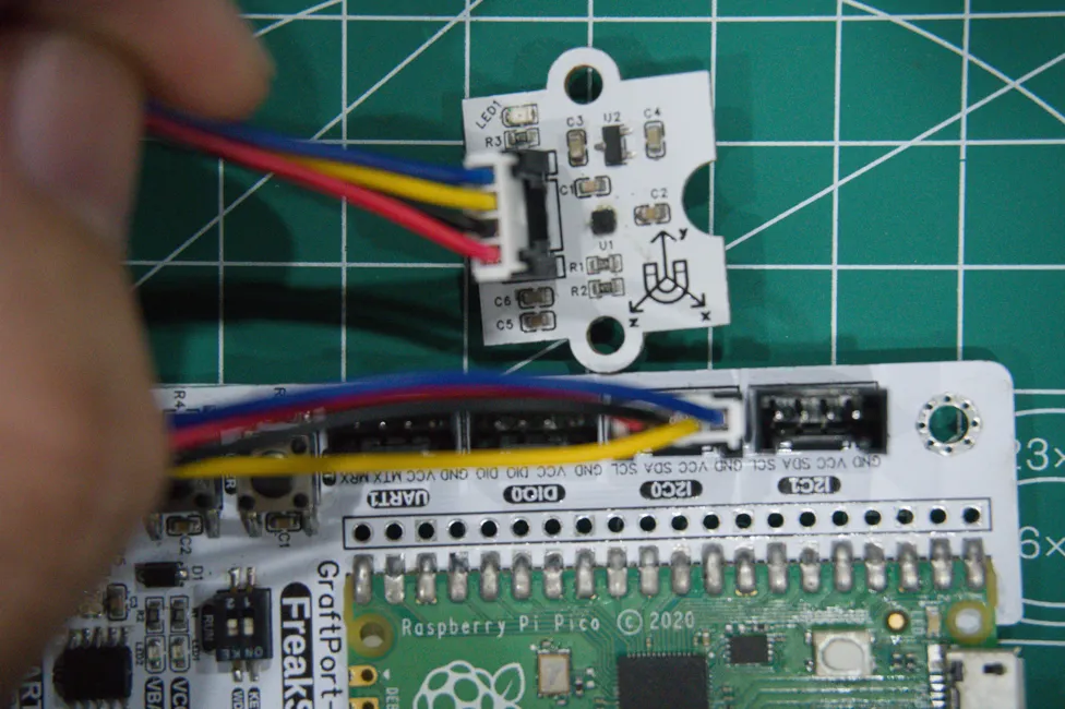
Here, we use the GraftPort-RP2040 development board for testing, and the MMC5983-based three-axis geomagnetic sensor module communicates with the main controller via the I2C interface.
Here, we first use the HY2.0-4P connection cable to connect the module to the GraftPort-RP2040 development board's I2C0 interface:
Development Board Pins | Module Pins | Description |
Pin 4 |
|
|
Pin 5 |
|
|
Here, we need to search for the relevant driver packages on uPyPI: https://upypi.net/zh/
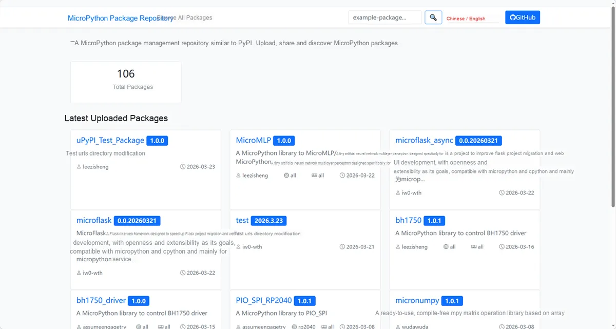
Enter mmc5983_driver to search, and the following will be displayed:

Click to copy the local installation command:
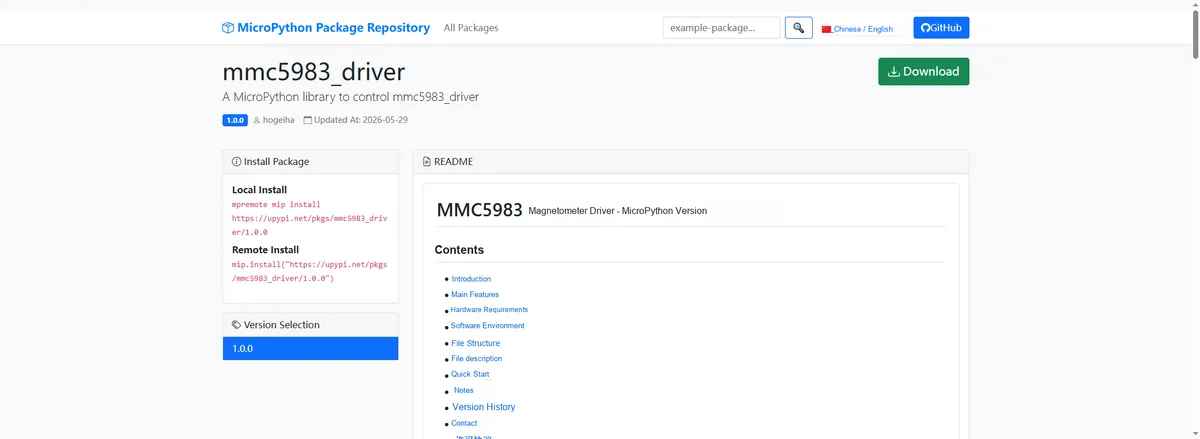
Import the module driver library code via the mip tool. Below are the usage commands for the mpremote tool:
mpremote mip install https://upypi.net/pkgs/mmc5983_driver/1.0.0Import the MicroPython driver code for the MMC5983-based 3-axis geomagnetic sensor module, then copy the following main.py code into our project:
# Python env   : MicroPython v1.23.0
# -*- coding: utf-8 -*-
# @Time    : 2025/1/15 3:00 PM
# @Author  : hogeiha
# @File    : main.py
# @Description : MMC5983 magnetometer continuous mode reading and operating mode iteration

# ======================================== Import Modules =========================================

# Import time module for delays
import time

# Import MicroPython Pin and SoftI2C classes
from machine import Pin, SoftI2C

# Import MMC5983 magnetometer driver library
from micropython_mmc5983 import mmc5983

# ======================================== Global Variables ============================================

# Automatically identify the sensor address, define a global target address list (supports multiple addresses; use [] even for a single one)
TARGET_SENSOR_ADDRS = [0x30]

# I2C pin and frequency definitions
I2C_SDA_PIN = 4
I2C_SCL_PIN = 5
I2C_FREQ = 400000

# ======================================== Functions ============================================

# ======================================== Custom Classes ============================================

# ======================================== Initialization configuration ===========================================

# Wait 3 seconds for the system to stabilize
time.sleep(3)
# Print startup message
print("FreakStudio: MMC5983 sensor continuous mode test")

# I2C initialization (compatible with I2C/SoftI2C)
i2c_bus = SoftI2C(sda=Pin(I2C_SDA_PIN), scl=Pin(I2C_SCL_PIN), freq=I2C_FREQ)


# Start scanning for devices on the I2C bus
devices_list: list[int] = i2c_bus.scan()
print("START I2C SCANNER")

# Check the I2C device scan result
if len(devices_list) == 0:
    print("No i2c device !")
    raise SystemExit("I2C scan found no devices, program exited")
else:
    print("i2c devices found:", len(devices_list))

# Iterate over the address list to initialize the target sensor
# Placeholder for the sensor object
sensor = None
for device in devices_list:
    if device in TARGET_SENSOR_ADDRS:
        print("I2c hexadecimal address:", hex(device))
        try:
            # Automatically identify and initialize the corresponding sensor
            sensor = mmc5983.MMC5983(i2c=i2c_bus)
            print("Sensor initialization successful")
            break
        except Exception as e:
            print(f"Sensor Initialization failed: {e}")
            continue
else:
    # Target device not found, raise an exception
    raise Exception("No target sensor device found in I2C bus")

# Set sensor to continuous measurement mode
sensor.operation_mode = mmc5983.CONTINUOUS

# ========================================  Main Program  ============================================

# Main loop: iterate through all operating modes and read magnetic field data
while True:
    # Iterate through all available operating modes
    for operation_mode in mmc5983.operation_mode_values:
        # Print current operating mode setting
        print("Current Operation mode setting: ", sensor.operation_mode)
        # Read magnetic field data 10 times consecutively in the current mode
        for _ in range(10):
            # Read X, Y, Z three-axis magnetic field strength (microtesla)
            magx, magy, magz = sensor.magnetic
            # Print magnetic field values, keeping two decimal places
            print(f"X: {magx:.2f}uT, Y: {magy:.2f}uT, Z: {magz:.2f}uT")
            # Print blank line as separator
            print()
            # Delay 0.5 seconds
            time.sleep(0.5)
        # Switch to the next operating mode
        sensor.operation_mode = operation_mode
Burn the code, open the terminal, and the output is as follows:
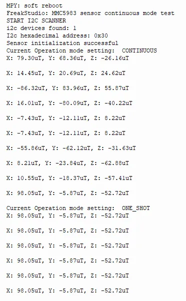
The I2C communication and initialization of the MMC5983 geomagnetic sensor function properly. In continuous mode, the three-axis geomagnetic readings update in real time as the attitude changes, and the readings remain stable after switching to single-shot mode, with normal operating response.
IV. Drivers
mmc5983_driver-1.0.0.zip 14 KB
5. BOM & Recommended Alternative Parts
None.
6. Revision History
Document Version | Date of Revision | Modifier | Modified Content |
v1.0 | 2026-05-12 | Ling Gaoxing | Initialize the document |
v1.1 | 2026-06-05 | Xin Ruili | Create an open version of the document, based on the internal document version v1.1. |
VII. Relevant Materials
7.1 Chip Datasheet
MMC5983.pdf 668 KB
7.2 Unique Icons for PCB Silk Screen