Contents
- I. Module Introduction
- II. Introduction to Main Chips
- 2.1 Chip Overview
- 2.2 Pin Definition
- 2.3 Functional Block Diagram
- 2.4 Performance Parameters
- 2.5 Reference Circuit
- 2.6 Chip Configuration
- 2.7 Communication Interfaces and Related Protocols
- 2.8 PCB Routing Notes
- III. Circuit Engineering
- 3.1 Circuit Source Engineering
- 3.2 Module Usage Instructions
- 3.3 Application Experiment
- IV. Drivers
- 5. BOM & Recommended Alternative Parts
- 6. Revision History
- VII. Relevant Materials
- 7.1 Chip Datasheet
- 7.2 Unique Icons for PCB Silk Screen
I. Module Introduction
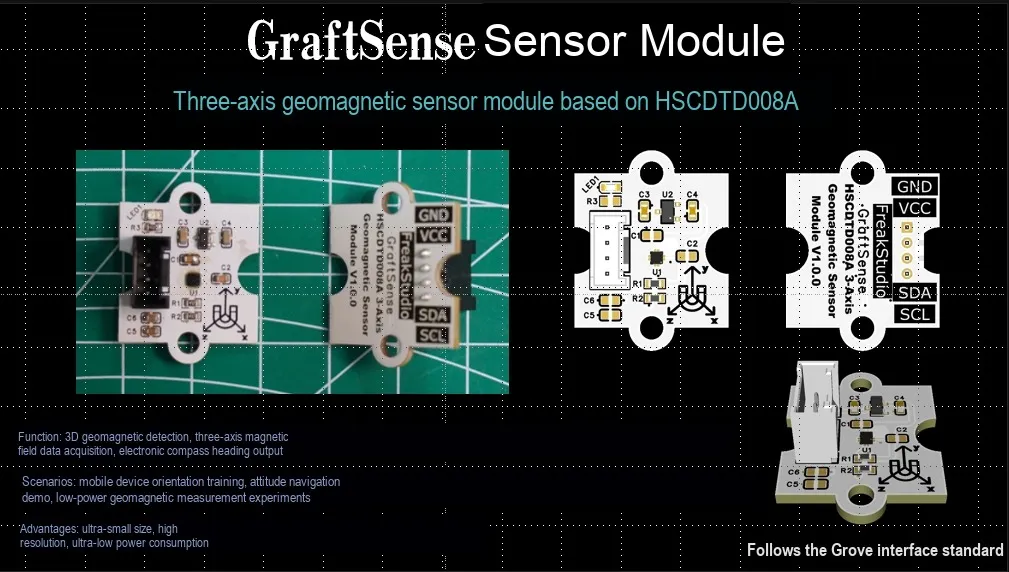
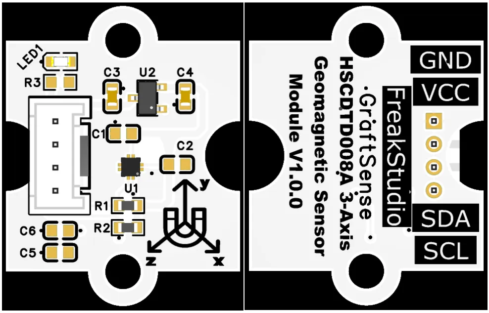
3-axis geomagnetic sensor module based on HSCDTD008A, which adopts the HSCDTD008A low-power 3-axis digital geomagnetic sensor solution, can measure the magnetic field strength of X / Y / Z three axes with high precision and output 14-bit digital signals, realizing electronic compass and orientation detection functions;The module is equipped with LDO voltage regulator circuit, power filtering and indicator circuit, powered by 3.3V and communicates with the main control via I²C interface. It has built-in temperature compensation, offset calibration and self-check functions, featuring extremely low power consumption and a resolution of up to 0.15μT/LSB, making it suitable for space and power consumption sensitive magnetic field sensing scenarios such as portable devices, wearable devices, and IoT terminals.
II. Introduction to Main Chips
HSCDTD008A is a 3-axis geomagnetic sensor with I²C interface, a measurement range of ±2.4mT, a resolution of 0.15μT/LSB, a supply voltage of 1.7–3.6V, and dimensions of 1.6×1.6×0.65mm FLGA-8 package, featuring low power consumption and built-in temperature compensation.
2.1 Chip Overview
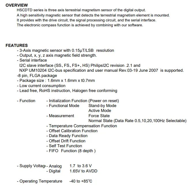
HSCDTD008A is a 3-axis geomagnetic sensor that integrates a driver circuit, signal processing and I²C interface, featuring a resolution of 0.15μT/LSB, supporting a data rate of 0.5~100Hz, temperature compensation, offset calibration and 8-level FIFO function. It adopts a 1.6×1.6×0.7mm FLGA-8 package, operates at 1.7-3.6V power supply, delivers low power consumption and complies with RoHS environmental protection standards.
2.2 Pin Definition
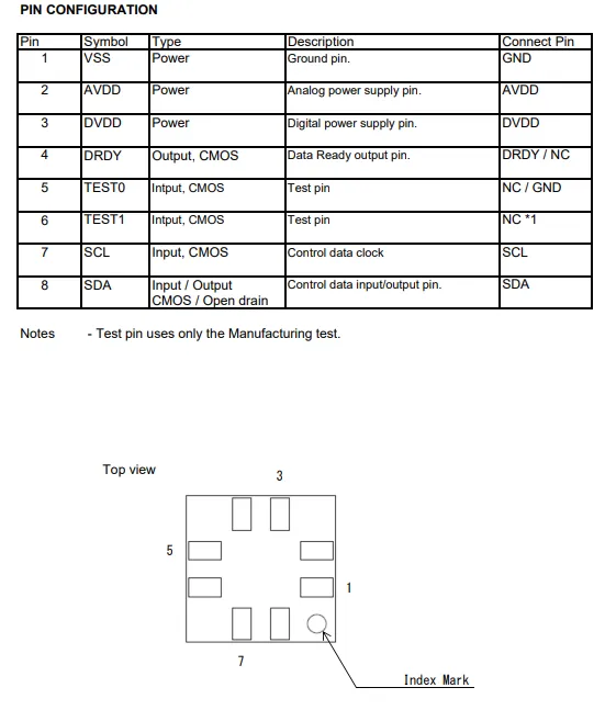
HSCDTD008A adopts an 8-pin FLGA package with clearly defined pin functions: Pin 1 is ground (VSS), Pins 2 and 3 are the analog power supply (AVDD) and digital power supply (DVDD) respectively; Pins 7 and 8 serve as the I²C clock (SCL) and data (SDA) lines, Pin 4 is the data ready (DRDY) output, and Pins 5 and 6 are test pins that should be left floating or grounded during normal operation.
2.3 Functional Block Diagram
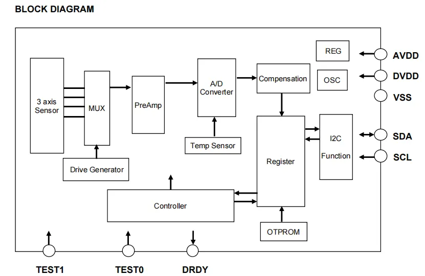
HSCDTD008A ’s driver generator provides excitation signals for the three-axis magnetic sensor; the acquired magnetic field signal is switched via a multiplexer, amplified by a preamplifier, and then converted into a digital signal by the ADC. Meanwhile, the data from the temperature sensor is also sent to the compensation module for temperature compensation and calibration, the processed data is stored in registers and can be output through the I²C interface. The controller coordinates the operation of each module according to the register configuration; at the same time, OTPROM stores calibration parameters, and the DRDY pin outputs a data ready signal, thereby realizing the geomagnetic measurement function.
2.4 Performance Parameters
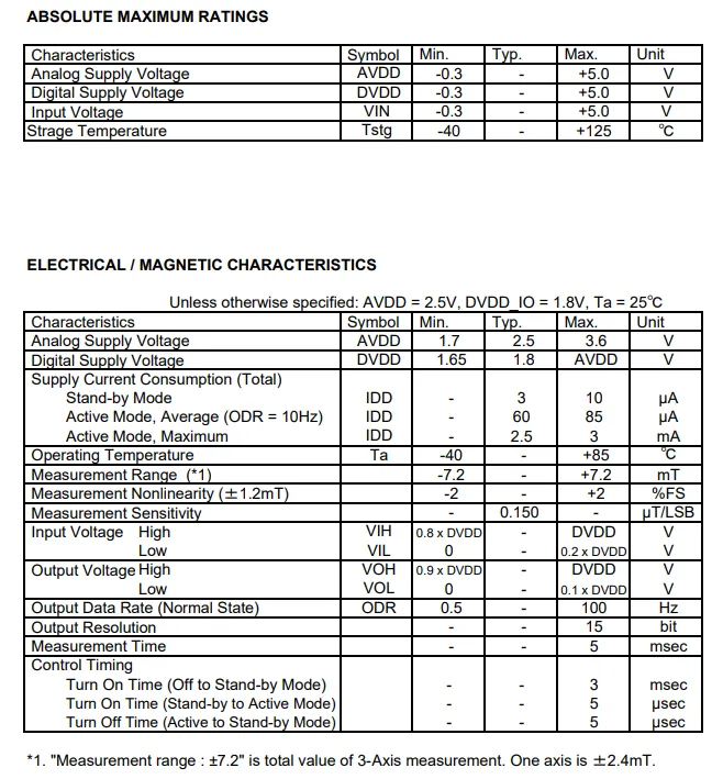
HSCDTD008A has absolute maximum rated analog/digital supply voltages of 1.7-3.6V and 1.65V~ respectively AVDD, with typical operating current of 3μA in standby mode and 60μA in 10Hz mode, a single-axis measurement range of ±2.4mT, a sensitivity of 0.15μT/LSB, 15-bit resolution, support for an output rate of 0.5~100Hz, and an operating temperature range of -40~+ 85°C.
2.5 Reference Circuit
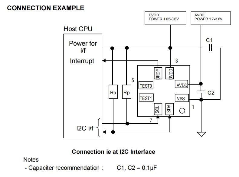
HSCDTD008A features AVDD (1.7–3.6 V) and DVDD (1.65–3.6 V) that supply power to the analog and digital circuits respectively, each connected to a 0.1 μF capacitor for filtering;SCL / SDA lines are connected to pull-up resistors Rp to communicate with the host's I²C interface, the DRDY pin can be connected to the host's interrupt pin for data-ready notification, and TEST0 / TEST1 pins are left floating or grounded to achieve stable power supply and digital communication for the sensor.
2.6 Chip Configuration
None.
2.7 Communication Interfaces and Related Protocols
2.7.1 I2C Communication
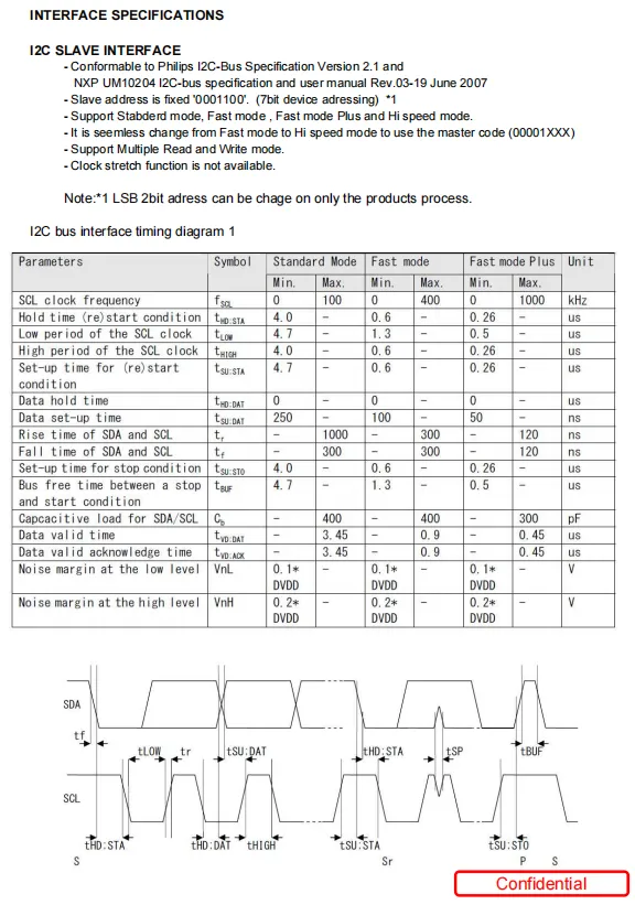
HSCDTD008A 's I ² C slave interface is compatible with the Philips I ² C 2.1 standard, with a fixed slave address of 0x18 , supporting standard, fast, fast enhancement, and high-speed modes, giving timing parameters such as SCL clock frequency, high and low level period, data establishment/hold time, and bus idle time under each mode, and with Sequence Diagram, the relationship between signal edge and key parameters is clarified.
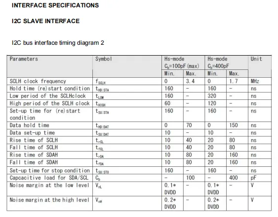
HSCDTD008A 's I²C high-speed mode (Hs - mode) interface timing, including parameters under the two conditions of bus capacitance of 100pF and 400pF, such as SCL clock frequency (max 3.4MHz/1.7MHz), high and low level periods, setup and hold time for start/repeated start conditions, data setup/hold time, signal rise/fall time and noise margin, etc.
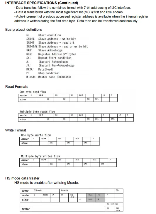
HSCDTD008A adopts the I²C bus protocol, where data is transmitted in big-endian format with the most significant bit first, and automatic increment of register addresses is supported. This paper also provides the bus timing definitions for single-byte/multi-byte read and write procedures, as well as the format specification for transmission switching via the master code in the high-speed (HS - mode) mode.
2.7.2 Registers
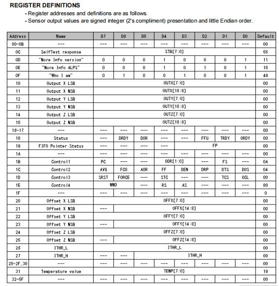
HSCDTD008A register table lists the addresses, names, bit definitions and default values of all registers ranging from 0x0C to 0x6F, covering self-test response, device information, 3-axis magnetic field output (little-endian signed format), status, FIFO pointers, control configurations, offset calibration, thresholds and temperature data, etc. Measurement control, data reading and function configuration of the sensor can be realized by reading and writing these registers.
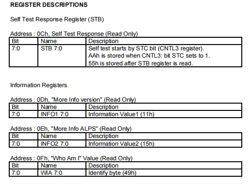
HSCDTD008A has registers including the self-test response register (0x0C, read-only; when self-test is initiated, 0xAA is written to it, and it becomes 0x55 after being read), as well as three read-only information registers: version information (0x0D, value 0x11), manufacturer information (0x0E, value 0x15) and device identification register (0x0F, value 0x49), which are used for self-test verification and device identification.
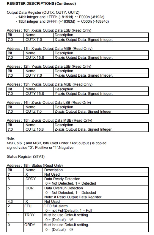
HSCDTD008A 's output data and status registers: the three-axis magnetic field data are stored in the X / Y / Z axis LSB / MSB registers in 14/15-bit signed integer format; the status register contains status flags including data ready (DRDY), data overrun (DOR) and FIFO full (FFU), which facilitate the host to determine data validity and read timing.
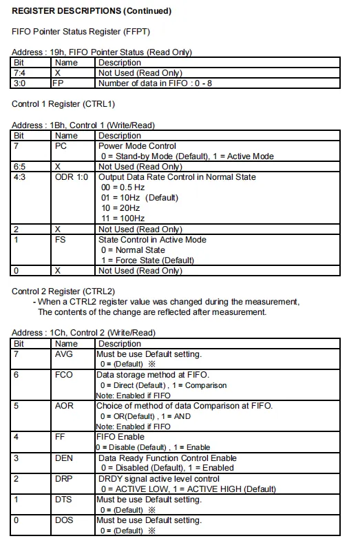
HSCDTD008A 's FIFO pointer status, Control Register 1 and Control Register 2: the lower 3 bits of the FIFO pointer status register (0x19) can be read to obtain the number of data entries (0-8) stored in the FIFO; Control Register 1 (0x1B) is used to configure the power mode (standby/active), output data rate (0.5-100Hz) and operating status.Control Register 2 (0x1C) supports the configuration of enable, data storage mode, comparison logic, data ready function, and the polarity of the enable, data storage mode, comparison logic, data ready function, and the polarity of the DRDY signal, and the modifications will take effect in the next measurement.
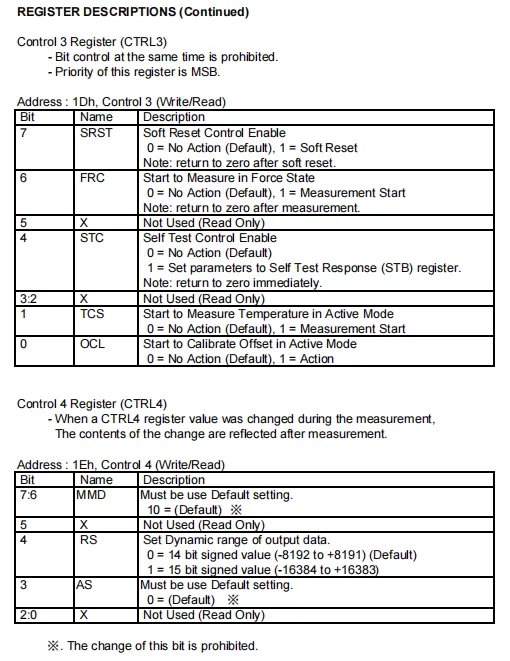
HSCDTD008A features Control Registers 3 and 4. Control Register 3 (0x1D) is configurable for software reset, forced state measurement, self-test, temperature measurement and offset calibration; note that the respective function bits must not be set simultaneously. Control Register 4 (0x1E) is used to set the dynamic range of output data, supporting 14-bit or 15-bit signed integer formats, with certain bits required to retain their default values.
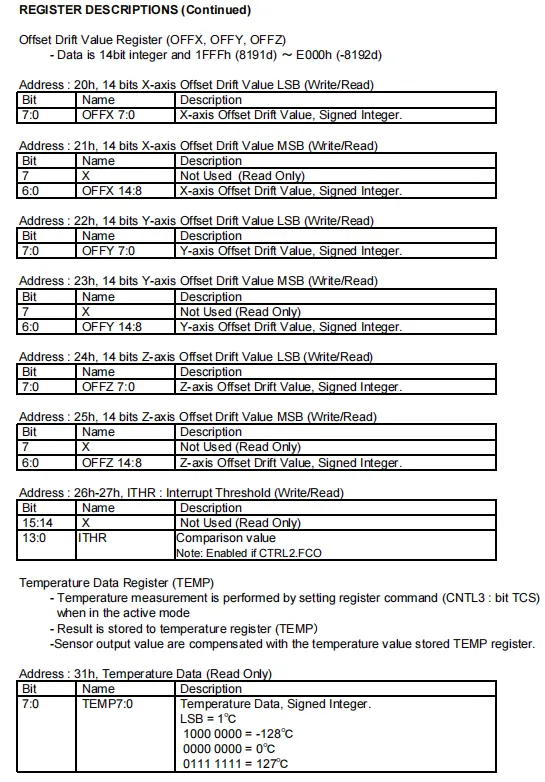
HSCDTD008A has offset drift, interrupt threshold and temperature data registers. The three-axis offset drift values are stored in their respective LSB / MSB registers in the format of 14-bit signed integers; the interrupt threshold register is used to configure the trigger value for the FIFO comparison mode; the temperature data register stores an 8-bit temperature value in units of 1℃/LSB, ranging from -128℃ to 127℃, which is used for temperature compensation of the sensor output.
2.8 PCB Routing Notes
None.
III. Circuit Engineering
3.1 Circuit Source Engineering
To obtain the source code of the circuit, please follow the official account [Freak Embedded]
3.2 Module Usage Instructions
The schematic diagram of this module is shown below:
SCH_Schematic1_3-Axis Geomagnetic Sensor Module Based on HSCDTD008A_v1.0.0_2026-05-12.pdf 2.0 MB
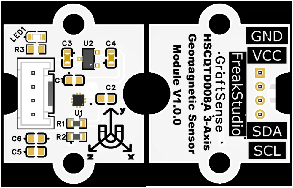
This module provides an IIC communication interface: it supports standard I2C communication rates, is compatible with 3.3V logic level, and can stably transmit the 14-bit digital signals of triaxial (X / Y / Z) magnetic field intensity collected by the HSCDTD008A. It is suitable for magnetic field sensing scenarios sensitive to space and power consumption such as portable devices, wearable devices and IoT terminals, and provides the system with reliable low-power, high-precision electronic compass and orientation sensing data interaction capabilities.
3.3 Application Experiment
Here, we use the GraftPort-RP2040 development board for testing, and the HSCDTD008A-based three-axis geomagnetic sensor module communicates with the main controller via the I2C interface.
Here, we first use the HY2.0-4P connection cable to connect the module to the GraftPort-RP2040 development board's I2C0 interface:
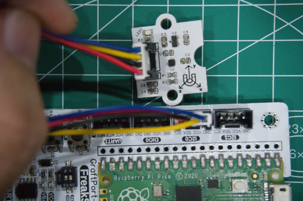
Development Board Pins | Module Pins | Description |
Pin 4 |
|
|
Pin 5 |
|
|
Here, we need to search for the relevant driver packages on uPyPI: https://upypi.net/zh/
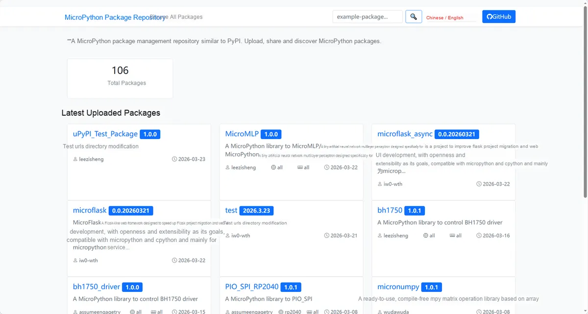
Enter hscdtd008a_driver to search, and the following will be displayed:
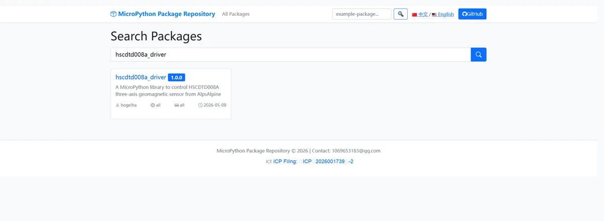
Click to copy the local installation command:
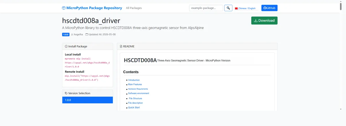
Import the module driver library code via the mip tool. Below are the usage commands for the mpremote tool:
mpremote mip install https://upypi.net/pkgs/hscdtd008a_driver/1.0.0Import the MicroPython driver code for the 3-axis geomagnetic sensor module based on HSCDTD008A, then copy the following main.py code into our project:
# Python env   : MicroPython v1.23.0
# -*- coding: utf-8 -*-
# @Time    : 2026/4/21 17:30
# @Author  : goctaprog
# @File    : main.py
# @Description : Test code for HSCDTD008A geomagnetic sensor driver
# @License : MIT

# ======================================== Import Modules =========================================

import time
import math
import sys
from machine import Pin, SoftI2C
import hscdtd008a
from sensor_pack.bus_service import I2cAdapter

# ======================================== Global Variables ============================================

# I2C pin and frequency configuration
I2C_SCL_PIN = 5
I2C_SDA_PIN = 4
I2C_FREQ = 400_000

# Target sensor I2C address list
TARGET_SENSOR_ADDRS = [0x0C]

# Expected chip ID (used for ID verification)
EXPECTED_CHIP_ID = 0x49

# Measurement loop parameters
MEAS_DELAY_MS = 250
MEAS_MAX_COUNT = 30

# ======================================== Functions ============================================

def show_state(sen: hscdtd008a.HSCDTD008A) -> None:
    """Print the sensor's current operating mode status"""
    print("in standby mode: %s; hi_dynamic_range: %s" % (sen.in_standby_mode(), sen.hi_dynamic_range))
    print("single meas mode: %s; continuous meas mode: %s" % (sen.is_single_meas_mode(), sen.is_continuous_meas_mode()))


def test_temperature(sen: hscdtd008a.HSCDTD008A, count: int = MEAS_MAX_COUNT) -> None:
    """Test the temperature measurement function, reading in a loop count times"""
    sen.enable_temp_meas(True)
    print("--- Temperature measurement test ---")
    show_state(sen)
    print(16 * "_")
    cnt = 0
    while cnt < count:
        status = sen.get_status()
        # Check the temperature data ready flag (TRDY, bit1)
        if status[3]:
            temp = sen.get_temperature()
            print("Sensor temperature: %d C" % temp)
            # Re-trigger the next temperature measurement
            sen.enable_temp_meas(True)
        else:
            print("status: %s" % str(status))
        time.sleep_ms(MEAS_DELAY_MS)
        cnt += 1


def test_force_mode(sen: hscdtd008a.HSCDTD008A, count: int = MEAS_MAX_COUNT) -> None:
    """Test single (Force) measurement mode, reading in a loop count times"""
    print("--- Magnetic field measurement: Force mode ---")
    show_state(sen)
    print(16 * "_")
    # Start single measurement mode
    sen.start_measure(continuous_mode=False)
    cnt = 0
    while cnt < count:
        status = sen.get_status()
        # Check the data ready (DRDY) or data overrun (DOR) flag
        if status[0] or status[1]:
            field = sen.get_axis(-1)
            # Trigger the next single measurement
            sen.start_measure(continuous_mode=False)
            print("magnetic field: X:%d Y:%d Z:%d" % (field[0], field[1], field[2]))
        else:
            print("status: %s" % str(status))
        time.sleep_ms(MEAS_DELAY_MS)
        cnt += 1


def test_continuous_mode(sen: hscdtd008a.HSCDTD008A, count: int = MEAS_MAX_COUNT) -> None:
    """Test periodic (Continuous) measurement mode, reading in a loop count times, with offset applied"""
    print("--- Magnetic field measurement: Continuous mode ---")
    # Enable offset application
    sen.use_offset = True
    sen.start_measure(continuous_mode=True)
    cnt = 0
    while cnt < count:
        status = sen.get_status()
        # Check the data ready flag (DRDY)
        if status[0]:
            field = sen.get_axis(-1)
            # Calculate the total magnetic field strength (square root of the sum of squares of the three axes)
            mag_strength = math.sqrt(field[0] ** 2 + field[1] ** 2 + field[2] ** 2)
            print("magnetic field: X:%d Y:%d Z:%d strength:%.2f" % (field[0], field[1], field[2], mag_strength))
        time.sleep_ms(MEAS_DELAY_MS)
        cnt += 1

# ======================================== Custom Classes ============================================

# ======================================== Initialization ==========================================

time.sleep(3)
print("FreakStudio: HSCDTD008A geomagnetic sensor test starting ...")

# Initialize I2C bus
i2c_bus = SoftI2C(sda=Pin(I2C_SDA_PIN), scl=Pin(I2C_SCL_PIN), freq=I2C_FREQ)

# Scan the I2C bus to check whether the device exists
devices_list = i2c_bus.scan()
print("I2C scan result: %s" % [hex(d) for d in devices_list])

if len(devices_list) == 0:
    raise RuntimeError("I2C scan found no devices")

# Look for the target sensor address in the scan results
sensor = None
for device_addr in devices_list:
    if device_addr in TARGET_SENSOR_ADDRS:
        print("Target sensor found at address: %s" % hex(device_addr))
        adapter = I2cAdapter(i2c_bus)
        sensor = hscdtd008a.HSCDTD008A(adapter)
        break

if sensor is None:
    raise RuntimeError("Target sensor not found on I2C bus")

# Read and verify the chip ID
chip_id = sensor.get_id()
print("Chip ID: %s (expected: %s)" % (hex(chip_id), hex(EXPECTED_CHIP_ID)))
if chip_id != EXPECTED_CHIP_ID:
    raise RuntimeError("Chip ID mismatch: got %s, expected %s" % (hex(chip_id), hex(EXPECTED_CHIP_ID)))

# Print the initial offset
print("Offset drift values: %s" % str(sensor.offset_drift_values))
print(16 * "_")
show_state(sensor)
print(16 * "_")

# Run self-test (must be in active mode)
sensor.start_measure(active_pwr_mode=True)
test_result = sensor.perform_self_test()
if not test_result:
    print("Sensor self-test FAILED: broken sensor or invalid mode")
    sys.exit(1)
print("Sensor self-test passed")

# ========================================  Main Program  ===========================================

try:
    while True:
        # Run the three test scenarios in turn
        test_temperature(sensor)
        print(16 * "_")
        test_force_mode(sensor)
        print(16 * "_")
        test_continuous_mode(sensor)
        print(16 * "_")
        # Exit the loop after all tests are complete
        break

except KeyboardInterrupt:
    print("Program interrupted by user")
except OSError as e:
    print("Hardware communication error: %s" % str(e))
except Exception as e:
    print("Unknown error: %s" % str(e))
finally:
    print("Cleaning up resources...")
    sensor.deinit()
    del sensor
    print("Program exited")
Burn the code, open the terminal, and the output is as follows:
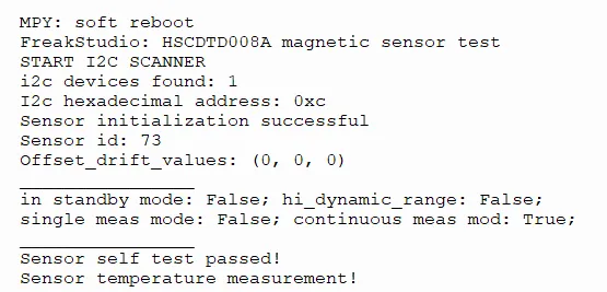
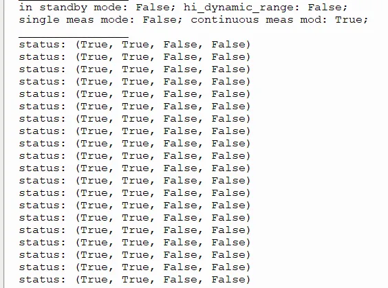
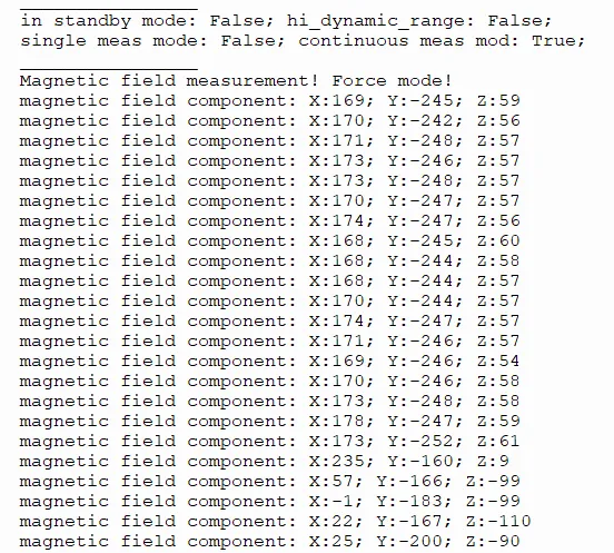
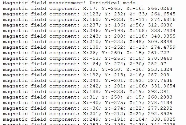
The HSCDTD008A magnetic sensor features normal I2C communication and initialization, passes the self-test, and supports the continuous measurement mode; in both force mode and periodic mode, the three-axis magnetic field data is stably output, with values updated in real time as the attitude changes.
IV. Drivers
hscdtd008a_driver-1.0.0.zip 27 KB
5. BOM & Recommended Alternative Parts
None.
6. Revision History
Document Version | Date of Revision | Modifier | Modified Content |
v1.0 | 2026-05-12 | Ling Gaoxing | Initialize the document |
v1.1 | 2026-06-05 | Xin Ruili | Create an open version of the document, based on the internal document version v1.1. |
VII. Relevant Materials
7.1 Chip Datasheet
HSCDTD008A.pdf 757 KB
7.2 Unique Icons for PCB Silk Screen