Contents
- I. Module Introduction
- II. Introduction to Main Chips
- 2.1 Chip Overview
- 2.2 Pin Definition
- 2.3 Functional Block Diagram
- 2.4 Performance Parameters
- 2.5 Reference Circuit
- 2.6 Chip Configuration
- 2.7 Communication Interfaces and Related Protocols
- 2.8 PCB Routing Notes
- III. Circuit Engineering
- 3.1 Circuit Source Engineering
- 3.2 Module Usage Instructions
- 3.3 Application Experiment
- IV. Drivers
- 5. BOM & Recommended Alternative Parts
- 6. Revision History
- VII. Relevant Materials
- 7.1 Chip Datasheet
- 7.2 Unique Icons for PCB Silk Screen
I. Module Introduction
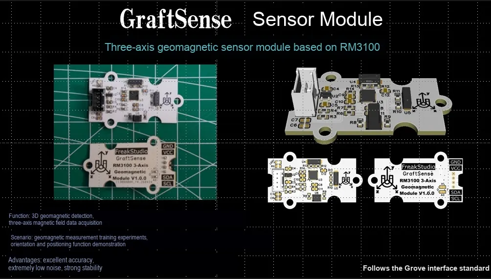
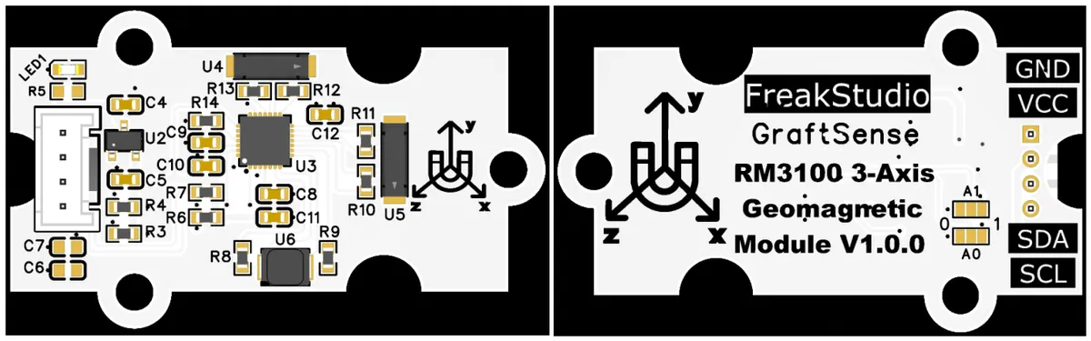
RM3100-Based Three-Axis Geomagnetic Sensor Module, adopts the RM3100 high-precision magnetic induction geomagnetic sensor solution. Leveraging its patented magnetic induction technology, it achieves ultra-low noise and ultra-high resolution, capable of accurately measuring the magnetic field intensities of the X / Y / Z three axes and outputting 16-bit digital signals, realizing the electronic compass function with a heading accuracy of up to ±0.25°;The module is equipped with an address selection circuit, LDO voltage regulator circuit, power filtering and indicator circuit. It is powered by 3.3V and communicates with the main controller via the I²C interface. Built-in with temperature compensation, it features no hysteresis, zero temperature drift and strong anti-interference capability, making it suitable for high-reliability scenarios such as industrial applications, drones and aerospace, as well as portable battery-powered devices.
II. Introduction to Main Chips
RM3100 is a PNI (now part of TDK) product high-precision 3-axis digital magnetometer that adopts patented fluxgate technology, featuring low noise, high resolution, and wide dynamic range, supports I2C / SPI interfaces, and is applied in electronic compasses, attitude navigation and industrial magnetic field monitoring.
2.1 Chip Overview
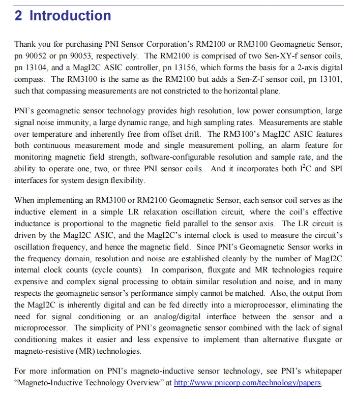
PNI RM3100 geomagnetic sensor adopts magnetoelectric induction technology, and measures the magnetic field through the coil LR oscillation circuit. It features high resolution, low power consumption, strong anti-interference and no offset drift, supports continuous/single measurement, alarm function, software-configurable resolution and sampling rate, and is compatible with I²C / SPI interfaces. Compared with fluxgate or MR Technology Implementation, it is simpler to implement and lower in cost, and is suitable for scenarios such as three-axis electronic compasses.
2.2 Pin Definition
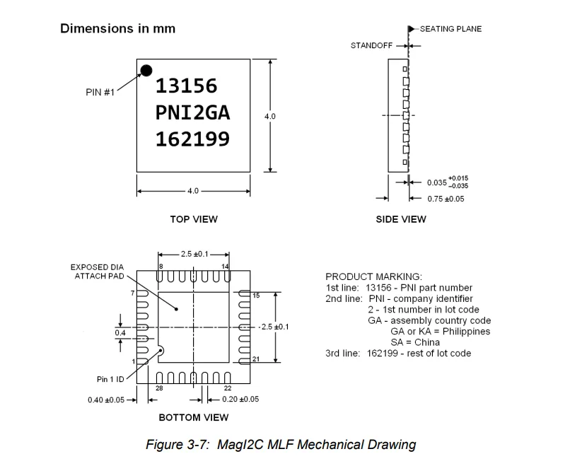
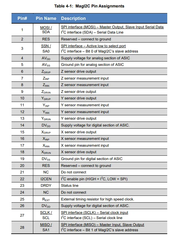
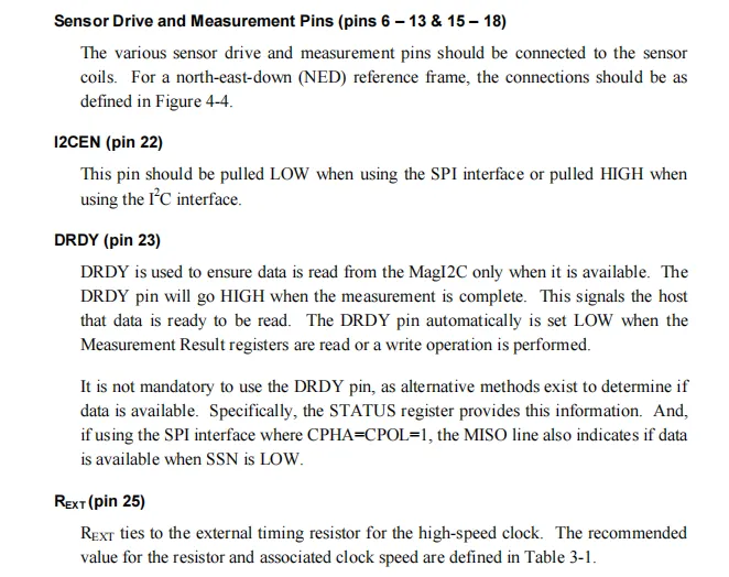
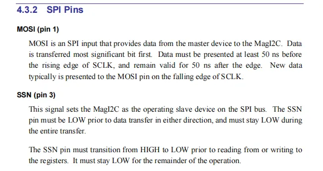
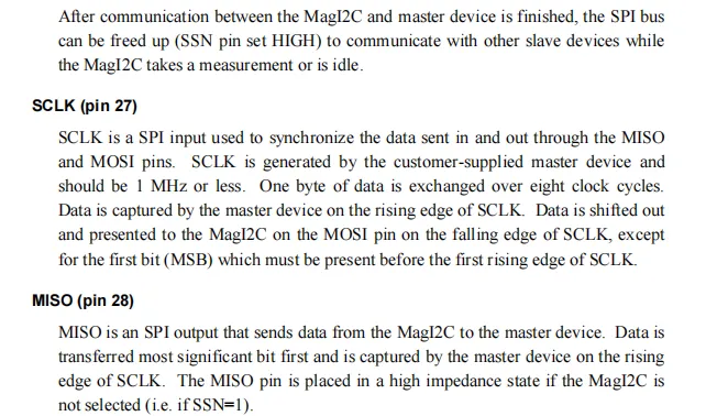
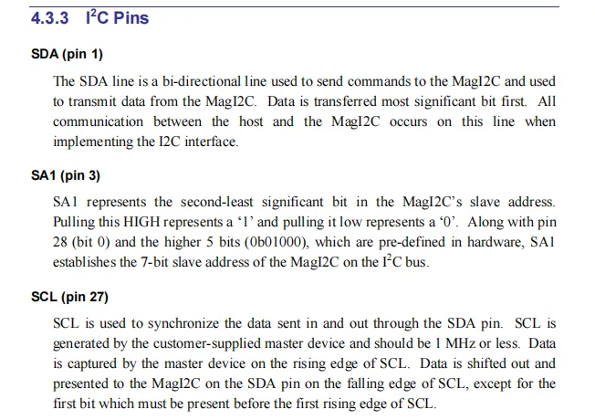
RM3100 adopts a 4×4mm, 28-pin MLF package, whose pin functions support I²C / SPI dual modes, which are selected via the I2CEN pin (high level for I²C, low level for SPI), and data interaction is realized via SCL/SDA (for I²C) or SCLK / MOSI / MISO / SSN (for SPI);
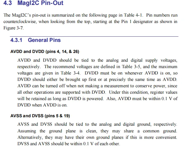
X / Y / ZDRVP / DRVN are the driving outputs for the 3-axis coil, X/Y / ZINP / INN are the corresponding measurement inputs for connecting to an external magnetic field coil;AVDD / AVSS, DVDD / DVSS are the analog/digital power supplies and grounds respectively, DRDY is the data ready status line, REXT is the external clock resistor, and the reserved pins shall be handled by connecting to ground or leaving floating.

2.3 Functional Block Diagram
None.
2.4 Performance Parameters
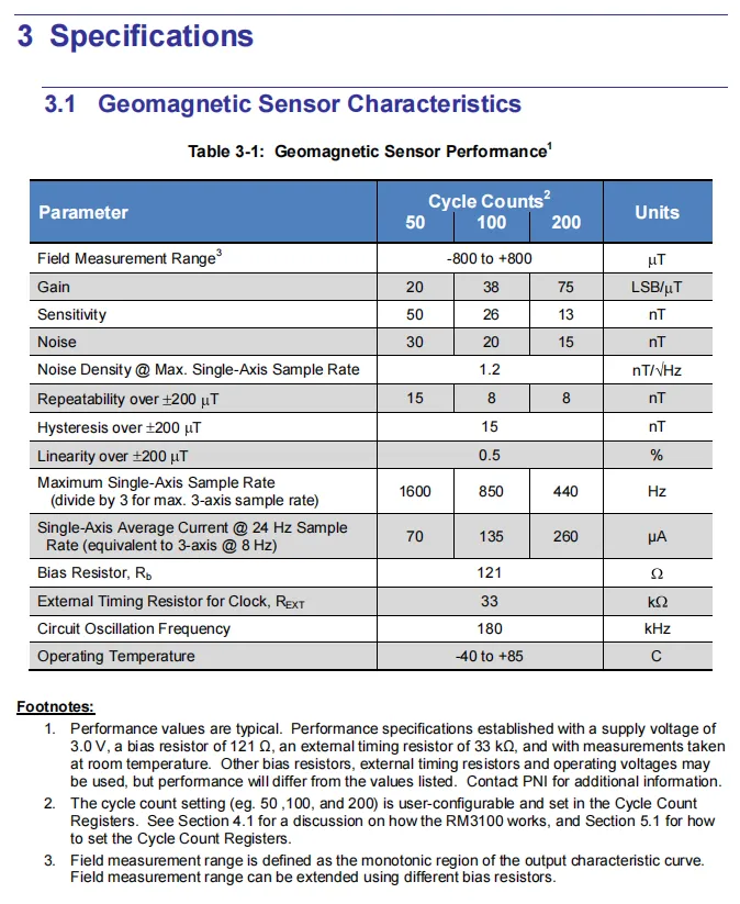
RM3100 geomagnetic sensor has a measurement range of ±800μT, and its resolution / noise improves as the configured Cycle Counts (50/100/200) increase. It achieves a sensitivity of up to 13nT, a noise level as low as 15nT, a maximum single-axis sampling rate of 1600Hz (approximately 533Hz for three-axis synchronization), a linearity error ≤0.5%, an operating current ranging from 70μA to 260μA depending on configuration, and an operating temperature range of -40~+ 85℃, demonstrating overall high-precision, low-noise, and high-dynamic magnetic field measurement capabilities.
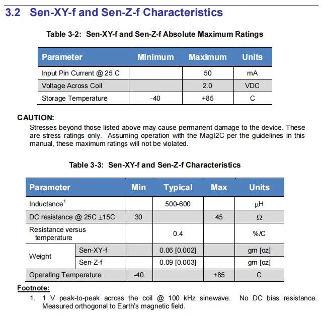
RM3100 supporting Sen-XY-f and Sen-Z-f sensor coils feature the following electrical characteristics and limiting parameters: maximum rated current of 50mA, voltage across the coils not exceeding 2.0V; typical coil inductance of 500-600μH, DC resistance of 30-45Ω, temperature coefficient of 0.4%/℃, operating and storage temperature both ranging from -40℃ to + 85℃;the XY axis and Z axis coils weigh 0.06g and 0.09g respectively.
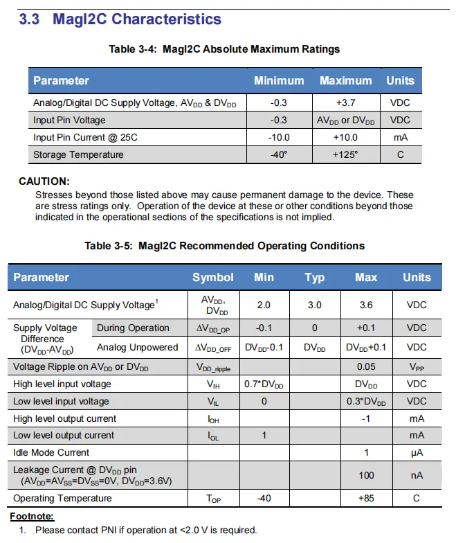
RM3100, the MagI2C controller has the following absolute maximum ratings: power supply voltage of -0.3V to + 3.7V, and storage temperature of -40°C to + 125°C. Under the recommended operating conditions, its analog/digital power supply voltage ranges from 2.0V to 3.6V (typical value: 3.0V), the operating current is as low as 1μA, clear specifications are defined for input/output level and ripple current, and the operating temperature ranges from -40°C to + 85°C.
2.5 Reference Circuit
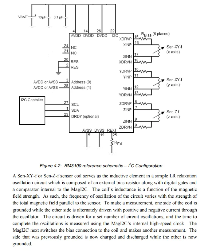
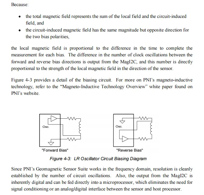
The RM3100 geomagnetic sensor is based on the magnetoinductive LR relaxation oscillation principle , and the coil and bias resistor of each axis form an oscillation circuit. The coil inductance will change with the parallel magnetic field strength, changing the oscillation frequency; the controller switches the forward/reverse bias polarity of the coil, measures the oscillation period difference twice, cancels the magnetic field influence generated by itself, obtains the clock count value proportional to the external magnetic field strength, and directly outputs a digital signal without additional signal conditioning to achieve high-precision and high-linearity magnetic field measurement.
2.6 Chip Configuration
None.
2.7 Communication Interfaces and Related Protocols
2.7.1 Registers
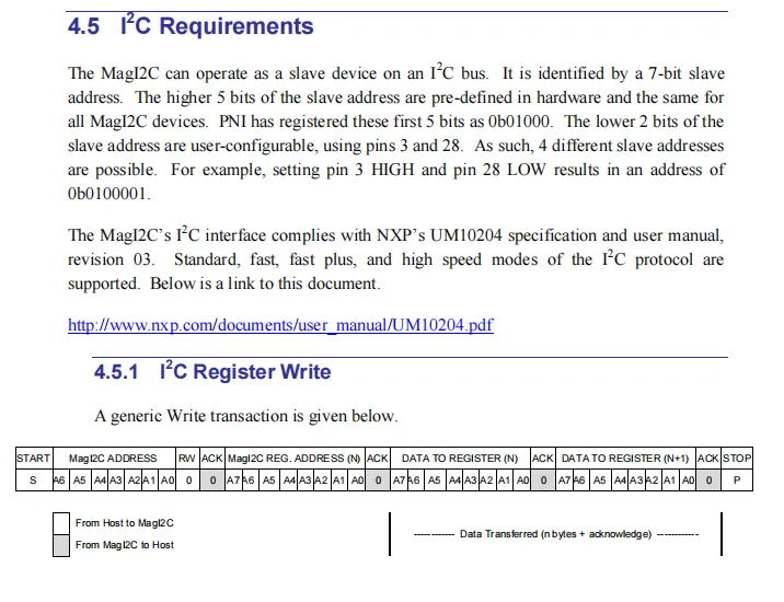
RM3100 (MagI2C) operates as an I²C slave device via its I²C interface; the upper 5 bits of its 7-bit address are fixed at 0b01000, while the lower 2 bits are configured via pins 3 and 28, supporting 4 distinct addresses. The interface is compliant with the NXP UM10204 standard, supports Standard-mode, Fast-mode, Fast-mode Plus and High-speed mode, and this document also presents the general I²C transaction format for register writes.
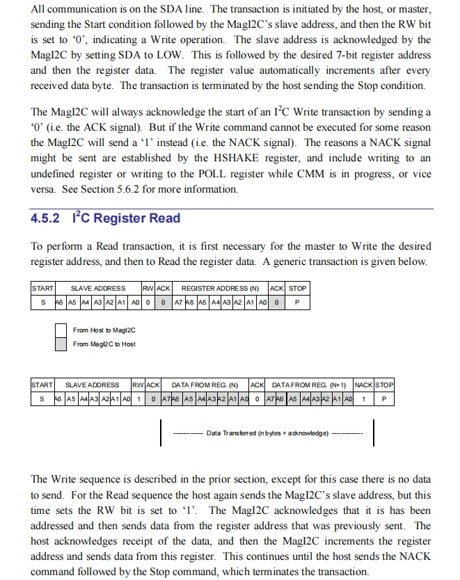
RM3100 (MagI2C) operates as follows during I²C write: the master sends a start signal, a slave address (with RW = 0), register address and data, and the device will automatically increment the address and send an acknowledge; during read, the register address must be written first, then a start signal and a read address (with RW = 1) are sent, the device outputs data from the specified address, the address is automatically incremented after the master acknowledges, and the process ends with a NACK and a stop signal, which explains the possible causes of NACK errors.
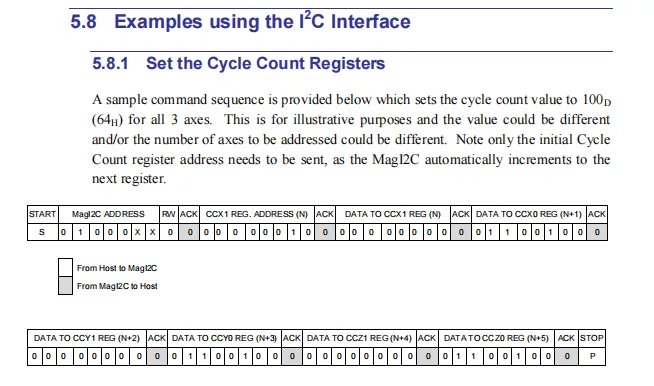
RM3100 (MagI2C) I²C interface configuration demonstrates how to set all three-axis I²C Cycle Count registers to decimal 100 (hexadecimal 0x64) via I²C. By utilizing the auto-increment feature of I²C addresses, only the starting register address needs to be sent, and subsequent data will be written to the following registers in sequence, which simplifies the multi-byte configuration process.
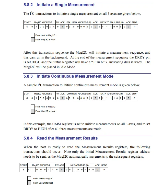
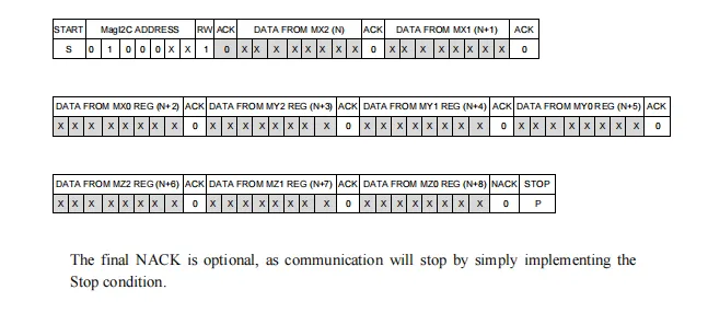
RM3100 (MagI2C) I²C measurement procedure example:
- Single measurement: Write a command to the
POLLregister to initiate 3-axis measurement; upon completion, theDRDYpin goes high, the status register flags data ready, and the chip automatically enters idle mode. - Continuous measurement: Configure
the CMMregister, set it to three-axis continuous measurement mode, and trigger theDRDYsignal upon completion. - Readout Procedure: The host first writes the address of the measurement result register, then initiates a read operation. By leveraging the auto-increment address feature, it reads all measurement data of the three axes in a single batch, and finally terminates the communication with a
NACKand a stop condition.
2.7.2 Registers
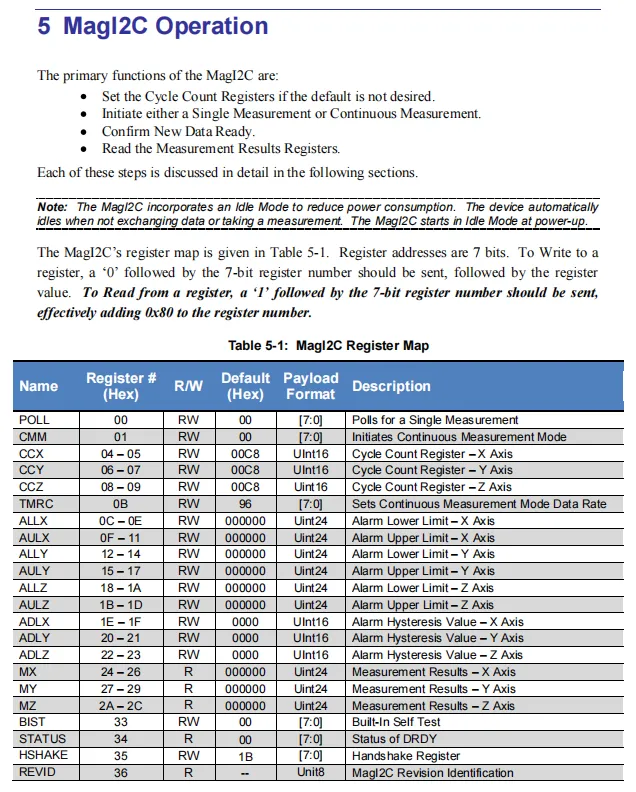
RM3100 (MagI2C) — its core functions and register mapping operation flow include configuring the Cycle Count register, initiating single/continuous measurement, confirming data readiness, and reading results; by default, it enters a low-power idle mode after power-up. The registers use 7-bit addresses: 0 serves as the read/write bit during write operations, and 0x80 must be added during read operations. The register mapping includes: POLL / CMM for measurement control, CCX / CCY / CCZ for sampling rate setting, MX / MY / MZ for storing three-axis measurement results, as well as functional registers for self-test, status, version number, and other purposes.
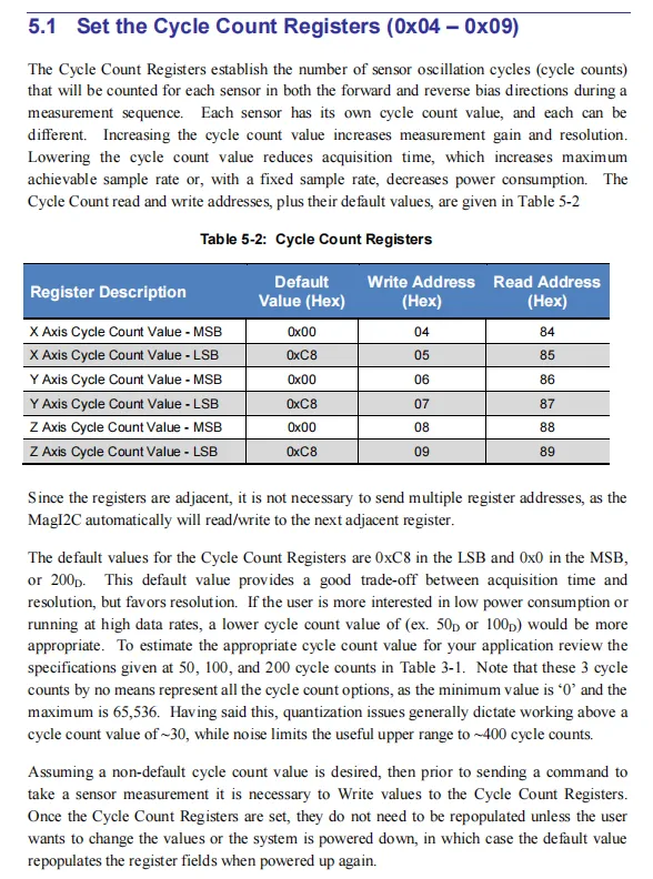
RM3100 Cycle Count register, with register addresses 0x04 – 0x09, is used to set the oscillation count for three-axis measurement: a larger value yields higher resolution / gain, while a smaller value delivers a higher sampling rate and lower power consumption. The default value for each axis is 200 (0x00C8); the addresses are consecutive and support batch configuration via auto-increment, no repeated writing is required after setup. The configurable range is 0~65536, and it is recommended to select a value between 30 and 400 in engineering applications to avoid quantization errors and noise limitations.
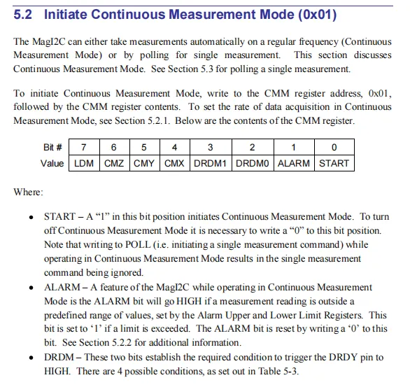
RM3100 (MagI2C) continuous measurement mode is enabled or disabled by writing to the 0x01 address CMM register; the functional bits of this register include: START bit (set to 1 to start, set to 0 to stop), ALARM bit (set to 1 when data exceeds preset upper and lower limits, requires manual clearing), DRDM bit (configures the trigger condition for the DRDY pin), as well as axis control and mode bits such as CMX / CMY / CMZ and LDM; in this mode, the single measurement command (POLL) will be ignored.
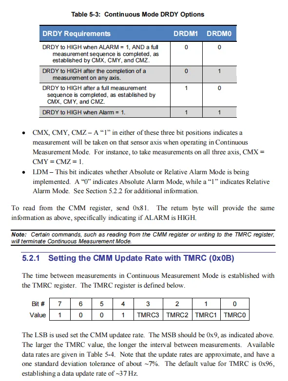
The CMM register's DRDM1 / DRDM0 bits configure the trigger condition of the DRDY pin (such as measurement completion on any axis, completion on all three axes, or alarm trigger);the CMX / CMY / CMZ bits are used to select the axes to be measured;the LDM bit sets the alarm to absolute or relative mode. Meanwhile, the TMRC register (address 0x0B) is used to configure the measurement interval in continuous mode: a larger value corresponds to a lower sampling rate, and the default value 0x96 corresponds to an update rate of approximately 37 Hz. Additionally, reading/writing the CMM or modifying the TMRC will terminate the continuous measurement mode.
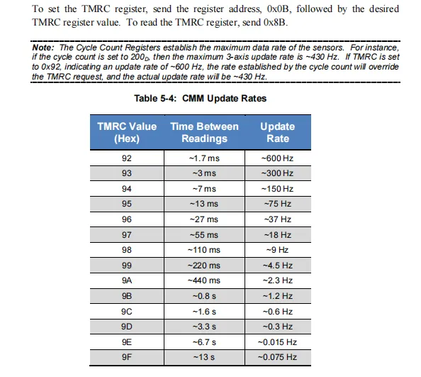
RM3100 's TMRC register is used to set the update rate for continuous measurement mode, with a write address of 0x0B and a read address of 0x8B. The larger the register value, the longer the interval between two measurements and the lower the update rate, which decreases in steps from 0x92 (approx. 600 Hz) to 0x9F (approx. 0.075 Hz).Note that the actual update rate is limited by the Cycle Count register; if the rate set by TMRC exceeds the hardware upper limit, it will be forcibly reduced by the latter. For example, when Cycle Count= 200, the maximum update rate for the three axes is approximately 430Hz.
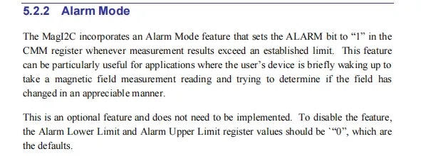
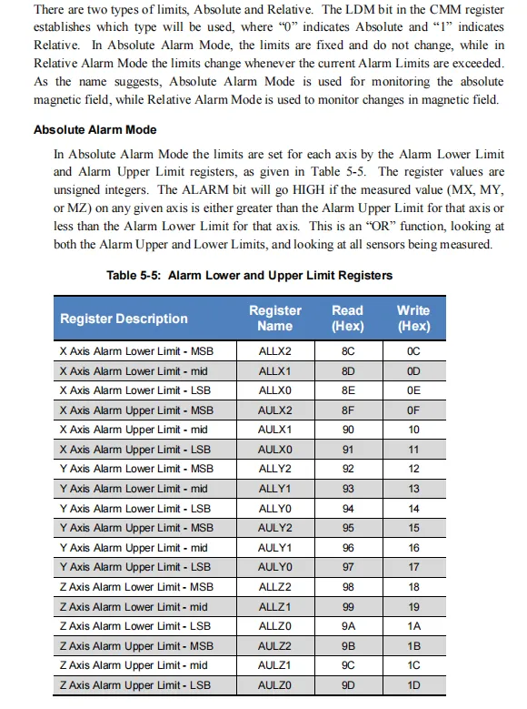
RM3100 features an alarm mode. When the measured value exceeds the preset range, this function will set the CMM register's ALARM bit to 1, making it suitable for magnetic field change detection scenarios. The default upper and lower limits are 0, and this function is disabled by default.
There are two types of alarm modes:
- Absolute mode (
LDM= 0): Uses fixed upper and lower limit registers (e. g.,ALLX/AULX), and an alarm will be triggered when the measured value exceeds this range. - Relative mode (
LDM= 1): The upper and lower alarm limits are automatically updated after each trigger to monitor the variation of the magnetic field.
The upper and lower alarm limits of each axis are set by a dedicated 24-bit register, whose address range covers the high, medium and low bytes of the three axes to facilitate batch configuration.
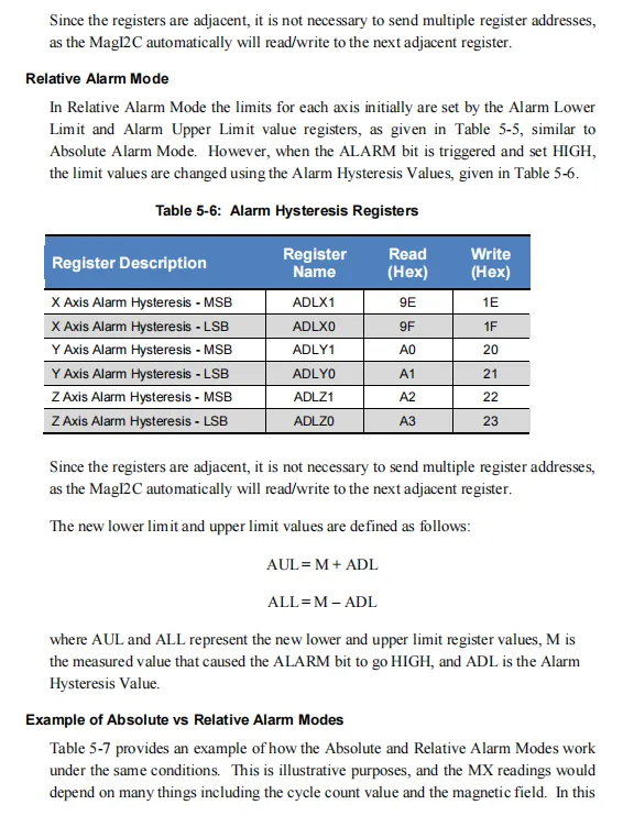
RM3100 In the initial state, the relative alarm mode is the same as the absolute mode, where the threshold is set via the upper and lower alarm limit registers; however, once the ALARM is triggered, the upper and lower limits will be automatically updated according to the hysteresis value of each axis (ADLX / ADLY / ADLZ): the new upper limit = the current triggered measurement value + the hysteresis value, and the new lower limit = the current triggered measurement value - the hysteresis value, so as to realize continuous monitoring of magnetic field changes; the addresses of related registers are consecutive, supporting batch read and write with automatic address increment.
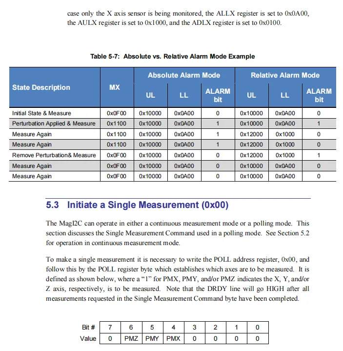
RM3100 has two alarm modes and a single measurement function:
- Example of Alarm Mode Comparison: When the magnetic field on the
Xaxis changes, the upper and lower limits of the Absolute Mode are fixed, and the alarm will be triggered continuously as long as the value exceeds the range; whereas the Relative Mode will automatically update the upper and lower limits according to the hysteresis value after each trigger, and only alarm again for changes exceeding the new threshold to achieve "change detection". - Single measurement mode: By writing to the
0x00 POLLregister, setting thePMX/PMY/PMZbits to select the axis to be measured, a single discontinuous measurement can be initiated. After the measurement is completed, theDRDYpin will be set high, and the chip will then return to idle mode.
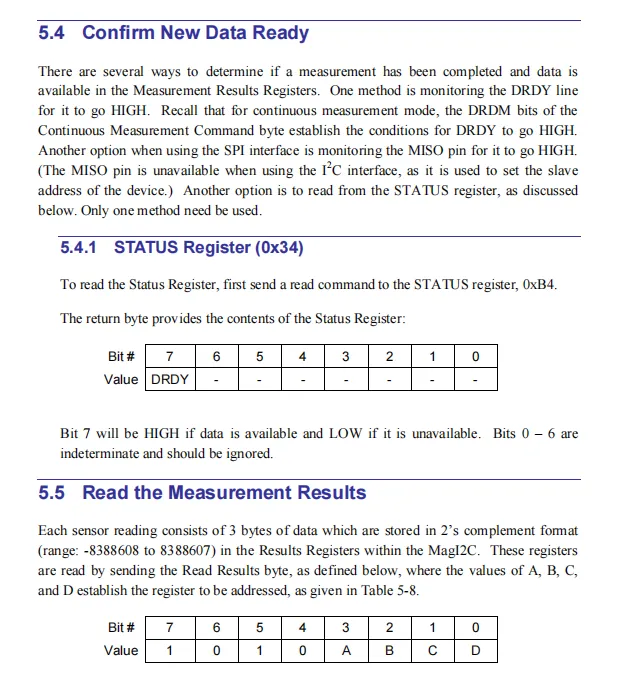
RM3100 The method for data ready confirmation and result reading is described as follows:
- Data Ready Confirmation: Measurement completion can be determined in three ways: monitoring the
DRDYpin level, monitoring theSPImodeMISOpin, or reading the0x34addressSTATUSregister (read address is0xB4), where a high level of itsBit7indicates that data is ready. - Measurement Result Reading: Each of the three-axis measurement results occupies 3 bytes and is stored in two's complement format (range: -8388608 to 8388607). It is read via a read instruction in a specific format (the upper 4 bits are fixed as
1010, and the lower 4 bitsA/B/C/Dspecify the target register), with consecutive addresses supporting automatic increment for batch reading.
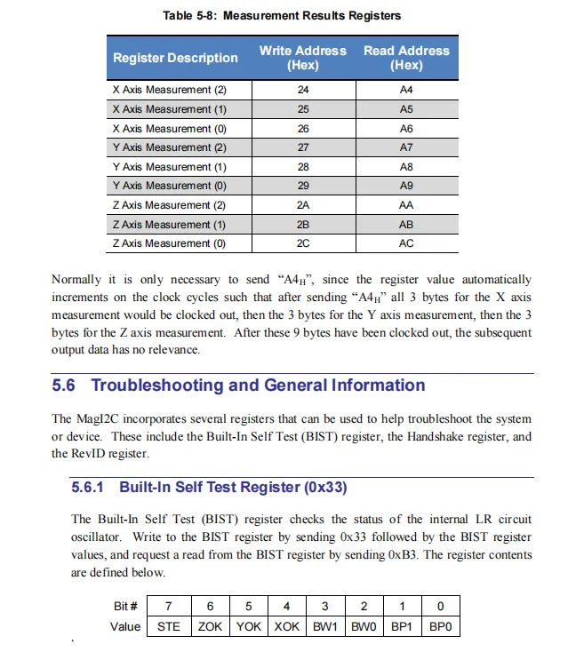
RM3100 The description of the measurement result registers and fault diagnosis function is as follows:
- Measurement Result Register: Each of the three-axis results occupies 3 bytes, with read addresses ranging from
A4toAC(A4corresponds to the highest byte of the X-axis). Since the addresses are consecutive, sending the read commandA4Hallows all 9 bytes of three-axis data to be read out in a single operation. - Built-In Self-Test (
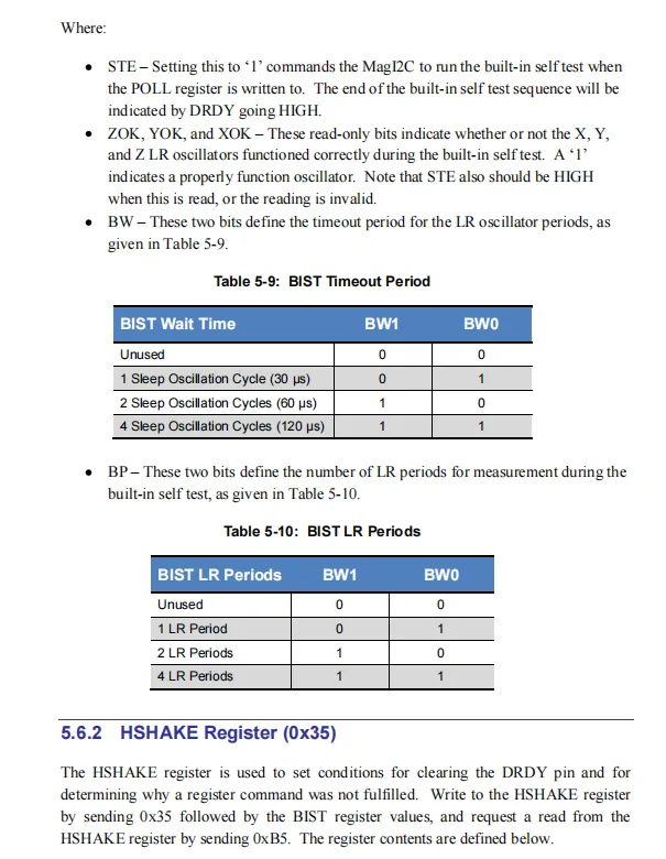
BIST) register at addressLRoscillation circuit via theBISTregister at address0x33. The read address is0xB3. Bits includingXOK/YOK/ZOKin the return value can feed back whether the circuit of each axis works properly, which is used for troubleshooting.
RM3100 Supplementary descriptions of the registers related to fault diagnosis are as follows:
BISTself-test register: The test is triggered by theSTEbit, and theDRDYbit is set high upon completion;ZOK/YOK/XOKbits feed back whether the three-axis oscillators are functioning properly;BWbit sets the timeout period, and theBPbit sets the number of test cycles.HSHAKEHandshake Register: Used to set the clearing condition for theDRDYpin (automatically cleared when writing to the register or reading results), and records error causes such as access to undefined registers, mode conflicts, and data not ready via theNACK0/1/2bits.
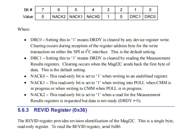
REVID Version Register: Read-only, the chip version information can be obtained by reading the address 0xB6, which is used for hardware identification and compatibility judgment.
2.8 PCB Routing Notes
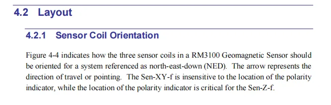
In the NED (North-East-Down) coordinate system, the correct installation orientation of the three-axis sensor coils is specified as follows: the polarity mark position of the X / Y axis coil (Sen-XY-f) does not affect the measurement, whereas the polarity mark position of the Z axis coil (Sen-Z-f) is critical, as it directly determines the measurement polarity.
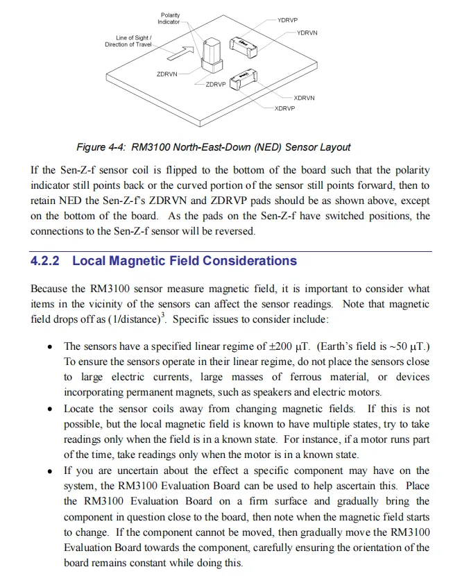
RM3100 NED Coil Layout in Coordinate System and PCB Design Essentials:
- Coil Layout: The orientation and pad connection mode of the three-axis coils in the
NED(North-East-Down) coordinate system. The position of the polarity mark of theZ-axis coil (Sen-Z-f) is critical. If it is mounted on the bottom of thePCB, itsZDRVNandZDRVPpads need to be connected in reverse correspondingly to maintain correct measurement polarity. - Precautions for Local Magnetic Field Interference: The linear measurement range of the sensor is ±200μT (the geomagnetic field is approximately 50μT). It shall be kept away from strong magnetic sources such as high-current devices, ferromagnetic materials, speakers and motors to avoid exceeding the linear range; for varying magnetic fields, sampling shall only be performed when the magnetic field is stable; if the interference is uncertain, the magnetic field influence range of the equipment can be tested via the evaluation board.
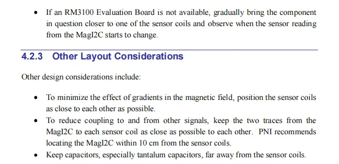
RM3100 's PCB layout recommendation: If there is no evaluation board, magnetic field interference can be checked by placing suspicious components close to the coil and observing the reading changes; at the same time, to reduce layer errors, the coil should be placed as close as possible; the differential wiring from MagI2C to each coil should also be closely parallel, and the distance between the MagI2C chip and the coil is recommended not to exceed 10cm; in addition, tantalum capacitors and other devices that may generate magnetic fields should be kept away from the coil.
III. Circuit Engineering
3.1 Circuit Source Engineering
To obtain the source code of the circuit, please follow the official account [Freak Embedded]
3.2 Module Usage Instructions
The schematic diagram of this module is shown below:
SCH_Schematic1_RM3100-Based 3-Axis Geomagnetic Sensor Module_v1.0.0_2026-05-12.pdf 2.2 MB
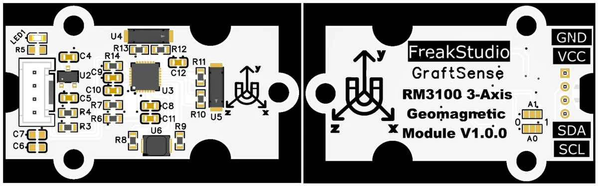
This module provides an IIC communication interface: it supports standard I2C communication rates, can flexibly configure multiple A0 and A1 pins for various I2C addresses, is compatible with 3.3V level, and can stably transmit the 16-bit digital signals of triaxial magnetic field strength on RM3100 -collected X / Y / Z axes. It is suitable for high-reliability scenarios such as industry, drones, and aerospace, as well as portable battery-powered devices, providing the system with reliable ultra-high precision hysteresis-free electronic compass and geomagnetic sensing data interaction capabilities.
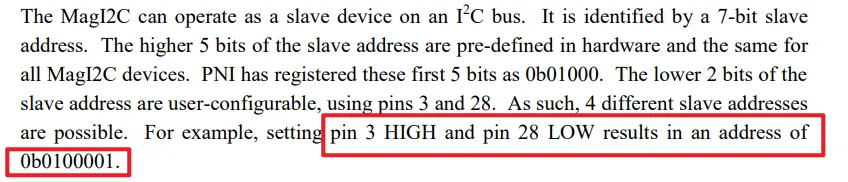
RM3100 's I ² C address is a combination of A0 (corresponding to pin 28) and A1 (corresponding to pin 3) . The high 5 bits of the address are fixed as 0b01000 , and the low 2 bits are determined by the levels of A1 and A0 ( A1 is the 2nd bit, and A0 is the 1st bit). The specific address selection is as follows:
| A1 (pin 3) | A0 (pin 28) | 7-bit I²C address (binary) | 7-bit I²C address (hexadecimal) | Write address (including R/W bit) | Read address (including R/W bit) |
|---|---|---|---|---|---|
| LOW | LOW | 0 | 0x20 | 0x40 | 0x41 |
| LOW | HIGH | 0 | 0x21 | 0x42 | 0x43 |
| HIGH | LOW | 0 | 0x22 | 0x44 | 0x45 |
| HIGH | HIGH | 0 | 0x23 | 0x46 | 0x47 |
3.3 Application Experiment
Here, we use the GraftPort-RP2040 development board for testing, and the RM3100-based three-axis geomagnetic sensor module communicates with the main controller via the I2C interface.
Here, we first use the HY2.0-4P connection cable to connect the module to the GraftPort-RP2040 development board's I2C0 interface:
Development Board Pins | Module Pins | Description |
Pin 4 |
|
|
Pin 5 |
|
|
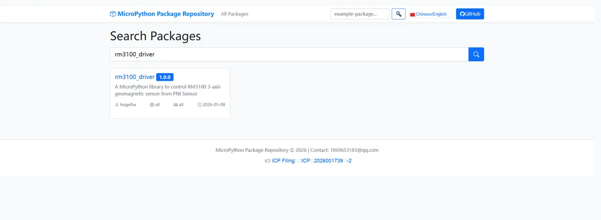
Here, we need to search for the relevant driver packages on uPyPI: https://upypi.net/zh/
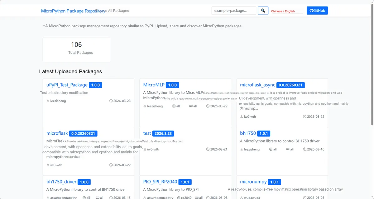
Enter rm3100_driver to search, and the following will be displayed:
Click to copy the local installation command:
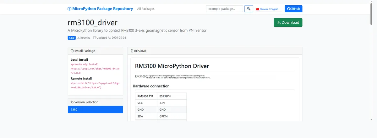
Import the module driver library code via the mip tool. Below are the usage commands for the mpremote tool:
mpremote mip install https://upypi.net/pkgs/rm3100_driver/1.0.0Import the MicroPython driver code for the RM3100-based three-axis geomagnetic sensor module, then copy the following main.py code into our project:
# Python env   : MicroPython v1.23.0
# -*- coding: utf-8 -*-
# @Time    : 2026/05/06 07:00
# @Author  : FreakStudio
# @File    : main.py
# @Description : RM3100 three-axis geomagnetic sensor driver test
# @License : MIT

# ======================================== Import Modules =========================================

import math
import time
from machine import Pin, SoftI2C
from sensor_pack.bus_service import I2cAdapter
import rm3100mod
from rm3100mod import RM3100

# ======================================== Global Variables ============================================

TARGET_SENSOR_ADDRS = [0x20, 0x21, 0x22, 0x23]
I2C_SCL_PIN = 5
I2C_SDA_PIN = 4
I2C_FREQ = 400_000
MEASURE_AXIS = "XYZ"
UPDATE_RATE = 6

# ======================================== Functions ============================================

# ======================================== Custom Classes ============================================

# ======================================== Initialization ==========================================

time.sleep(3)
print("FreakStudio: RM3100 geomagnetic sensor test")

# ========================================  Main Program  ===========================================

if __name__ == '__main__':
    i2c_bus = SoftI2C(sda=Pin(I2C_SDA_PIN), scl=Pin(I2C_SCL_PIN), freq=I2C_FREQ)

    devices_list = i2c_bus.scan()
    print("START I2C SCANNER")

    if not devices_list:
        raise SystemExit("I2C scan found no devices")
    print("I2C devices found:", len(devices_list))

    sensor = None
    for device in devices_list:
        if device in TARGET_SENSOR_ADDRS:
            print("I2C address:", hex(device))
            try:
                sensor = RM3100(I2cAdapter(i2c_bus), address=device)
                print("Sensor initialization successful")
                break
            except Exception as e:
                print("Sensor init failed:", e)

    if sensor is None:
        raise SystemExit("No target sensor found on I2C bus")

    try:
        self_test = sensor.perform_self_test()
        self_test_ok = self_test[0] and self_test[1] and self_test[2]
        print("Self test result: %s  %s" % (self_test_ok, str(self_test)))
        print("Sensor id:", sensor.get_id())
        print(16 * "_")

        for axis in MEASURE_AXIS:
            print("%s axis cycle count: %d" % (axis, sensor.get_axis_cycle_count(axis)))

        sensor.start_measure(axis=MEASURE_AXIS, update_rate=UPDATE_RATE, single_mode=True)
        print("Is continuous meas mode:", sensor.is_continuous_meas_mode())
        wait_time_us = rm3100mod.get_conversion_cycle_time(UPDATE_RATE)
        time.sleep_us(wait_time_us)
        if sensor.is_data_ready():
            for axis in MEASURE_AXIS:
                print("%s axis magnetic field: %d" % (axis, sensor.get_meas_result(axis)))

        print("Continuous meas mode measurement")
        sensor.start_measure(axis=MEASURE_AXIS, update_rate=UPDATE_RATE, single_mode=False)
        print("Is continuous meas mode:", sensor.is_continuous_meas_mode())

        while True:
            time.sleep_us(wait_time_us)
            mag_field_comp = next(sensor)
            if mag_field_comp:
                mfs = math.sqrt(sum(v ** 2 for v in mag_field_comp))
                print("X: %d; Y: %d; Z: %d; mag field strength: %.2f" % (
                    mag_field_comp[0], mag_field_comp[1], mag_field_comp[2], mfs))

    except KeyboardInterrupt:
        print("Program interrupted by user")
    finally:
        sensor.deinit()
        print("Sensor deinitialized")
Burn the code, open the terminal, and the output is as follows:
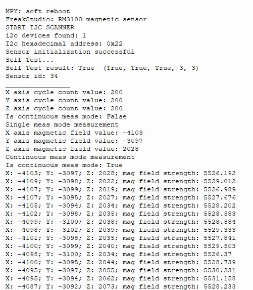
The RM3100 geomagnetic sensor features normal I2C communication and initialization, passes the self-test, supports single and continuous measurement modes, stably outputs three-axis magnetic field data, updates the values in real time as the attitude changes, and operates with normal response.
IV. Drivers
rm3100_driver-1.0.0.zip 20 KB
5. BOM & Recommended Alternative Parts
None.
6. Revision History
Document Version | Date of Revision | Modifier | Modified Content |
v1.0 | 2026-05-12 | Ling Gaoxing | Initialize the document |
v1.1 | 2026-06-05 | Xin Ruili | Create an open version of the document, based on the internal document version v1.1. |
VII. Relevant Materials
7.1 Chip Datasheet
RM3100.pdf 1.6 MB
7.2 Unique Icons for PCB Silk Screen