Contents
- I. Module Introduction
- II. Introduction to Main Chips
- 2.1 Chip Overview
- 2.2 Pin Definition
- 2.3 Functional Block Diagram
- 2.4 Performance Parameters
- 2.5 Reference Circuit
- 2.6 Chip Configuration
- 2.7 Communication Interfaces and Related Protocols
- 2.8 PCB Routing Notes
- III. Circuit Engineering
- 3.1 Circuit Source Engineering
- 3.2 Module Usage Instructions
- 3.3 Application Experiment
- IV. Drivers
- 5. BOM & Recommended Alternative Parts
- 6. Revision History
- VII. Relevant Materials
- 7.1 Chip Datasheet
- 7.2 Unique Icons for PCB Silk Screen
I. Module Introduction
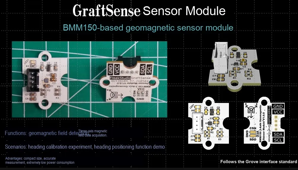
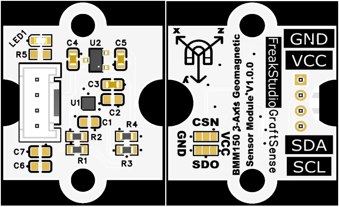
Triaxial geomagnetic sensor module based on BMM150, which adopts Bosch BMM150 low-power triaxial geomagnetic sensor solution, can accurately measure the magnetic field strengths of the X / Y / Z three axes and calculate the azimuth angle, realizing the electronic compass function;The module is equipped with an address selection circuit, LDO voltage regulator circuit, power filtering and indicator circuit. It is powered by 3.3V and communicates with the main control via the I²C / SPI interface. It supports wide-range measurement of ±1300µT, with built-in temperature compensation and noise suppression. It can be combined with an accelerometer and a gyroscope to realize 9-axis attitude fusion, and is suitable for orientation and attitude detection scenarios of mobile phones, watches, drones and various portable devices.
II. Introduction to Main Chips
Bosch BMM150 is a FlipCore technology-based low-power 3-axis digital geomagnetic sensor. It adopts an ultra-compact WLCSP package, supports I²C / SPI interfaces, and is suitable for scenarios including electronic compasses, navigation and AR.
2.1 Chip Overview
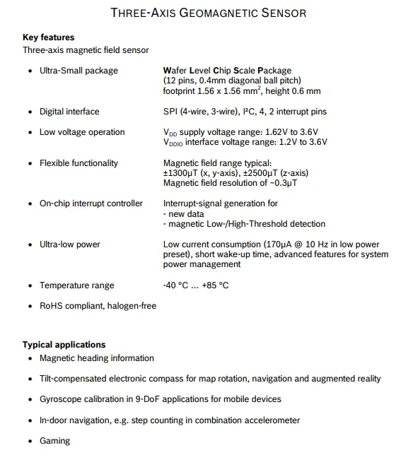

Bosch BMM150 is a 3-axis geomagnetic sensor based on FlipCore technology. It features an ultra-compact WLCSP package measuring 1.56×1.56×0.6mm, supports I²C / SPI interfaces, operates on a supply voltage of 1.62-3.6V, has a resolution of approximately 0.3μT, draws power as low as 170μA at 10Hz, and integrates an interrupt controller. It is specifically designed for applications such as electronic compasses, navigation systems and mobile devices.
2.2 Pin Definition
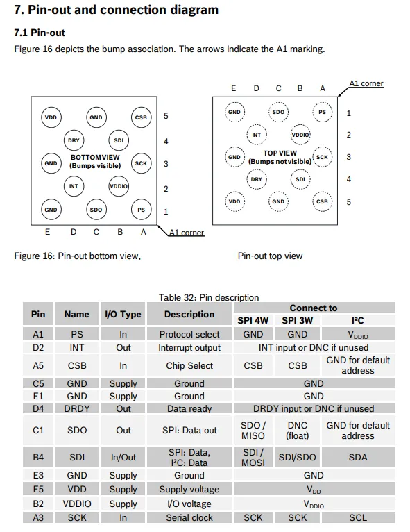
BMM150 adopts a 12-pin WLCSP package and supports I²C / SPI communication: VDD / VDDIO are power supply pins, and GND is the ground pin;The PS pin selects the protocol (I²C by connecting to VDDIO, SPI by connecting to ground);SCL / SDA (for I²C) or SCK / SDI / SDO / CSB (for SPI) are responsible for data transmission;INT and DRDY are interrupt/data ready outputs, which can be configured as needed or left floating.
2.3 Functional Block Diagram
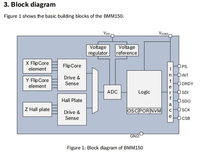
BMM150 adopts the X / Y -axis FlipCore units and the Z -axis Hall Plate unit to sense 3D magnetic fields. After being conditioned by the driving and sensing circuits, the analog signals are converted to digital values by the ADC, processed by the built-in logic unit, and output via the I²C / SPI interface. It also integrates a voltage regulator, reference source, oscillator, power-on reset module and non-volatile memory to provide stable power supply and configuration management for the sensor.
2.4 Performance Parameters
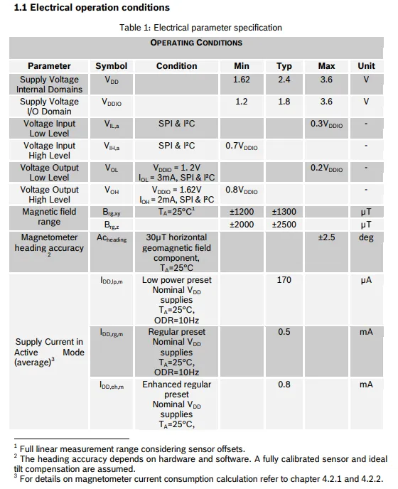
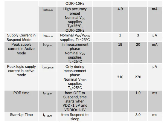
BMM150 has a supply voltage VDD of 1.62-3.6V, VDDIO of 1.2-3.6V; its magnetic field measurement range is ±1300μT for the X / Y axes and ±2500μT for the Z axis, with a heading accuracy of ±2.5°; in terms of current consumption, it draws 170μA in low-power mode, 0.5mA in normal mode, 4.9mA in high-precision mode, merely 1μA in suspend mode, and has a peak measurement current of approximately 18mA; it also specifies key parameters including I / O level specifications, power-on reset time (≤1ms) and start-up time (≤3ms).
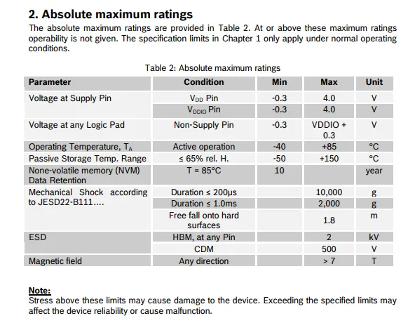
BMM150 absolute maximum ratings: power supply / IO pin voltage -0.3~4.0V, operating temperature -40~+ 85℃, storage temperature -50~+ 150℃, withstand up to 10000g shock, 2kV HBM ESD, and may fail in a strong magnetic field greater than 7T in any direction; exceeding these conditions will result in device damage or reduced reliability.
2.5 Reference Circuit
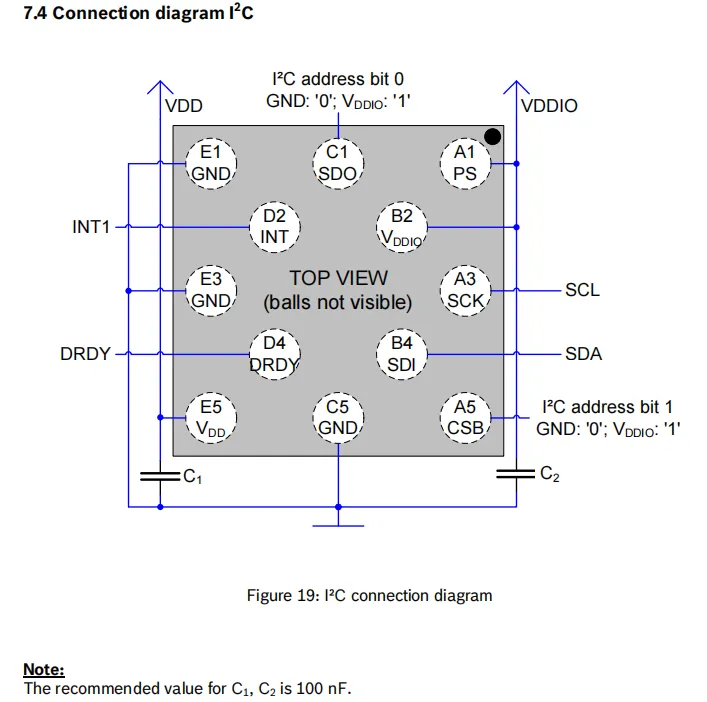
BMM150 PS pin is connected to VDDIO to select I²C mode;SCL / SDA correspond to SCK / SDI pins respectively;VDD and VDDIO power supply pins are each connected to a 100nF decoupling capacitor;CSB and SDO pins are grounded to set the default I²C address;INT and DRDY pins can be used as interrupt or data ready signal outputs.
2.6 Chip Configuration
None.
2.7 Communication Interfaces and Related Protocols
2.7.1 SPI Communication
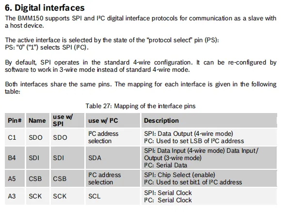
BMM 150's PS pin selects the Communication Protocol (low level for SPI, high level for I²C). SPI supports 4-wire / configurable 3-wire mode, I²C sets the address bits via the SDO and CSB pins. Pins including SCK, SDI, SDO, and CSB are reused in both protocols to realize bidirectional data transmission between the host and the sensor.
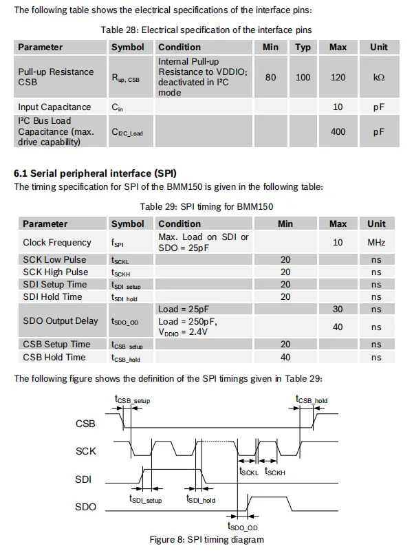
BMM150 provides in its SPI interface section the internal pull-up resistor (typical 100kΩ) of the CSB pin, input capacitance, and the I²C bus load capacitance; the SPI section defines a maximum clock frequency of 10MHz, and specifies key timing parameters including the SCK high and low level pulses, SDI setup/hold time, SDO output delay, and CSB setup/hold time.
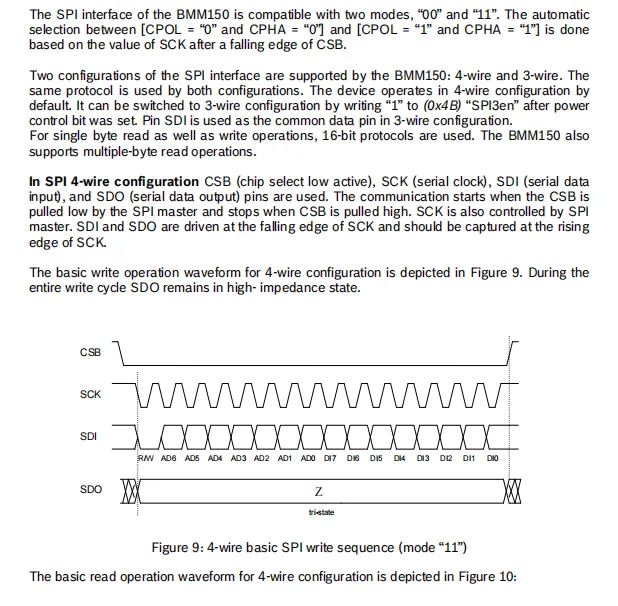
BMM150 SPI interface supports two clock modes (CPOL / CPHA 00 and 11, auto-detected), defaults to 4-wire mode (CSB / SCK / SDI / SDO), and is also configurable to 3-wire mode; during write operations, SDO remains in a high-impedance state, data is driven on the falling edge of SCK and sampled on the rising edge, supports single-byte read/write and multi-byte read, and provides the Sequence Diagram for 4-wire SPI write operation.
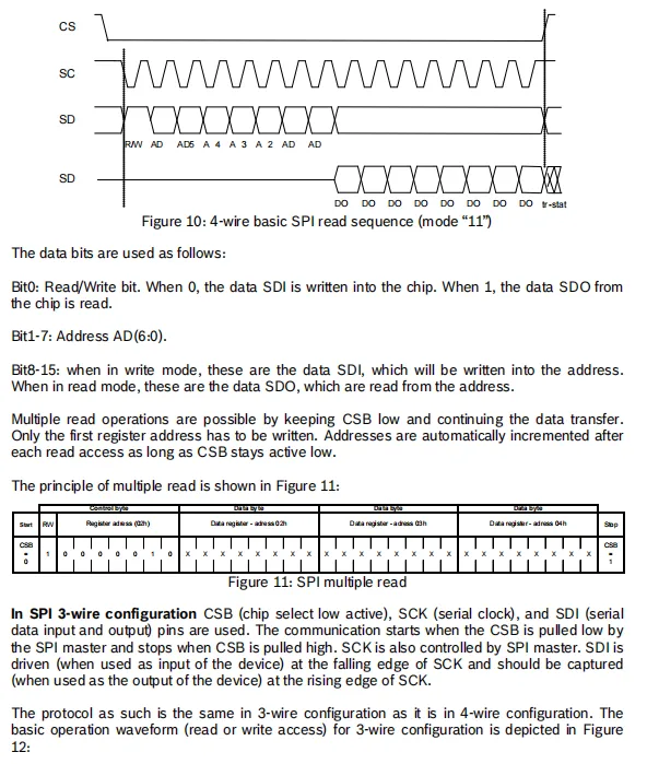
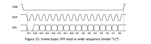
BMM150 features 16-bit frame format for both read and write operations in 4-wire mode (including R / W bits, address bits and data bits), and supports multi-byte read with automatic address increment; in 3-wire mode, the SDI pin is reused as a bidirectional data terminal, with the same protocol logic as the 4-wire mode. Meanwhile, Sequence Diagrams for read/write operations in both modes are provided, which specify the transmission timing of each signal and the definition of the frame structure.
2.7.2 I2C Communication
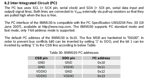
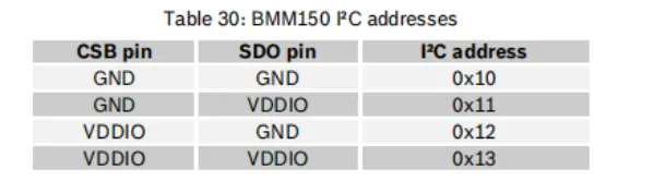
BMM150 I²C interface uses SCL (SCK pin) and SDA (SDI pin) for communication, supports standard/fast mode, and only supports 7-bit addresses; the default address is 0x10, which can be configured to four addresses CSB and SDO pin levels: 0x10 / 0x11 / 0x12 / 0x13, to avoid bus conflicts.
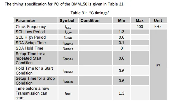
BMM150 I²C timing defines the key timing parameters of the interface, with a maximum clock frequency of 400kHz; it specifies the high and low level periods of SCL, the setup/hold times of SDA, the setup and hold times for start/repeated start/stop conditions, as well as the bus idle time and other specifications, to ensure stable and reliable I²C communication.
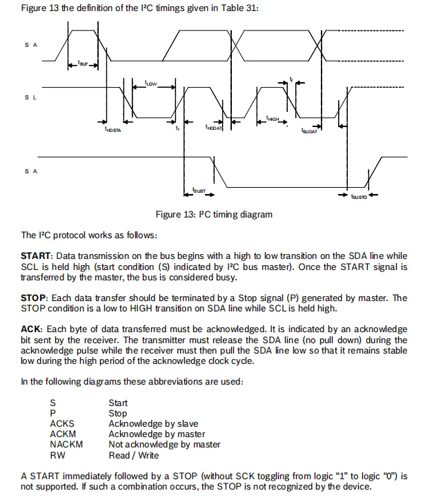
Key timing parameters such as the start / repeated start / stop conditions, data setup / hold time of SCL and SDA signals are demonstrated via a Sequence Diagram, and the operating logic of START (SCL is at high level while SDA transitions from high to low), STOP (SCL is at high level while SDA transitions from low to high) and ACK (the receiver pulls SDA low for acknowledgment) is explained, meanwhile the abbreviations and symbols used in communication are defined.
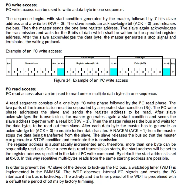
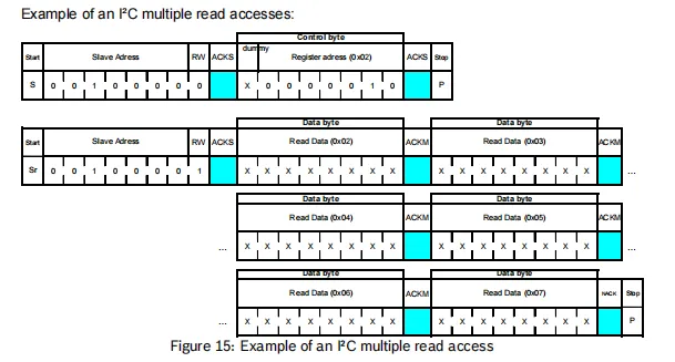
BMM150 write operations are completed in the sequence of a start signal, slave address + write bit, register address, data byte, and stop signal, with the slave required to send an ACK at each stage; read operations follow the format of "write address first + repeated start + read data", support multi-byte read with automatic address increment, the master sends an ACK after each data read, and finally sends a NACK to terminate the operation; the chip has a built-in 50ms watchdog to prevent bus hang-up, and the figure also provides timing examples for single-byte write and multi-byte read.
2.7.3 Registers
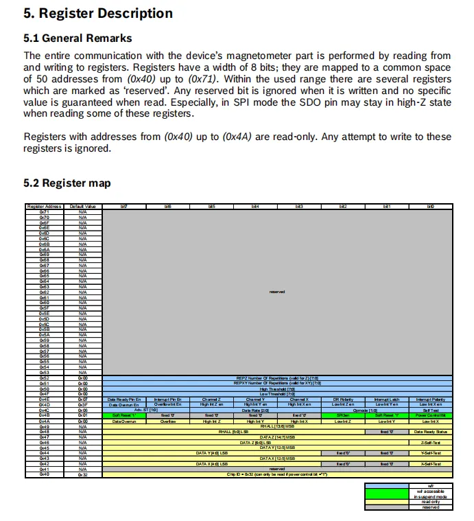
The magnetometer of BMM150 communicates by reading and writing 8-bit registers, with an address range of 0x40 to 0x71, among which 0x40 to 0x4A are read-only registers where write operations are invalid; some addresses are reserved bits, writes to them will be ignored and the read values are undefined, and the access permissions and function distribution of the registers are distinguished by colors.
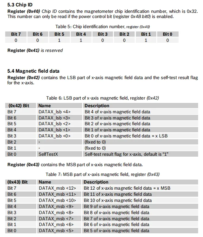
BMM150 chip's ID and magnetic field data registers: Register 0x40 is a read-only chip ID with a fixed value of 0x32, which is readable only after the power control bit is enabled;0x41 is a reserved register;X -axis magnetic field data consists of two registers: 0x42 (containing LSB data and the self-test flag bit SelfTestX) and 0x43 (containing MSB data). The lower 5 bits of 0x42 serve as the lower 5 bits of the data, and the 8 bits of 0x43 serve as the upper 8 bits of the data, together forming a 13-bit magnetic field data.
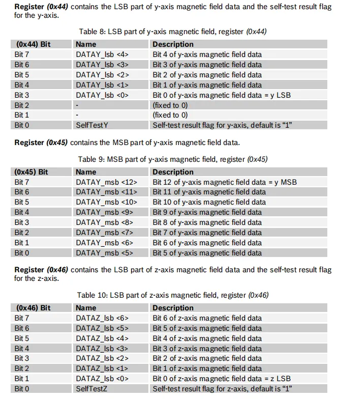
BMM150 three-axis magnetic field data registers: Y -axis magnetic field data consists of 0x44 (lower 5 bits of data + the SelfTestY flag at bit 0) and 0x45 (upper 8 bits of data);Z -axis data is formed by 0x46 (lower 7 bits of data + the SelfTestZ flag at bit 0) in conjunction with the subsequent high-byte register, and each register details the data bit distribution and self-test flag bits.
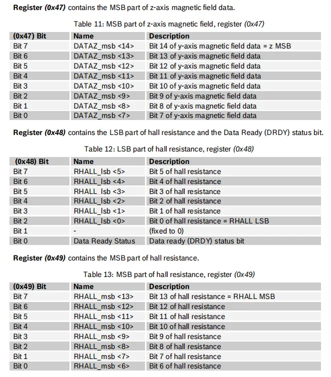
BMM150 Z -axis magnetic field and Hall resistance related registers: 0x47 Z holds the upper 8 bits of the Z-axis magnetic field data, which forms the complete data together with the lower 7 bits of 0x46;0x48 holds the lower 5 bits of the Hall resistance data, with bit 0 serving as the data ready (DRDY) status flag;0x49 holds the upper 8 bits of the Hall resistance data, which together with 0x48 constitutes the 14-bit Hall resistance value.
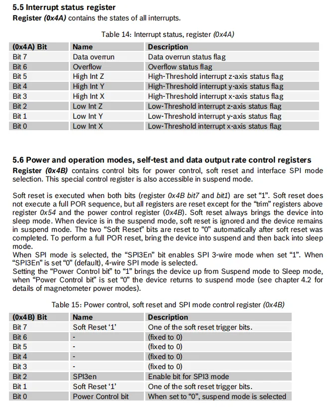
BMM150 has an interrupt status and power control register set: 0x4A is the interrupt status register, which records data overflow, over-range, and the trigger status of high and low thresholds for the three axes;0x4B is the control register, where bit 0 controls the power mode (0 for suspend, 1 for wake-up), bit 2 selects SPI 3-wire mode, setting both bit 1 and bit 7 to 1 simultaneously triggers a soft reset (which automatically clears after reset), and the soft reset only resets some registers and puts the device into sleep mode.
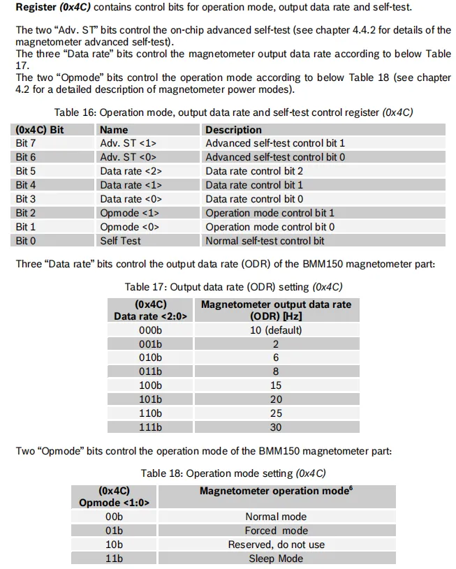
The control register of BMM150 (0x4C) is used to configure the operating mode, output data rate (ODR) and self-test function:
- Bits 7-6
Adv. STare used to control the advanced self-test, and bit 0 is the normal self-test control bit; - Bits 5-3
Data ratesets the output data rate, ranging from 2 to 30 Hz with a default value of 10 Hz; - Bits 2-1
Opmodecontrol the operating mode, supporting normal mode, forced mode and sleep mode (10b is a reserved mode).
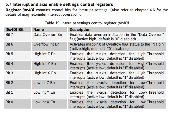
BMM150 interrupt setting control register (0x4D), which is used to configure the enable options for various interrupts: bit 7 enables the data overflow flag, bit 6 enables the mapping of overflow status to the INT pin; bits 5-3 and bits 2-0 respectively control the detection enable of the three-axis high and low threshold interrupts, which are disabled by default, and the corresponding interrupt function can be enabled by setting the bits.
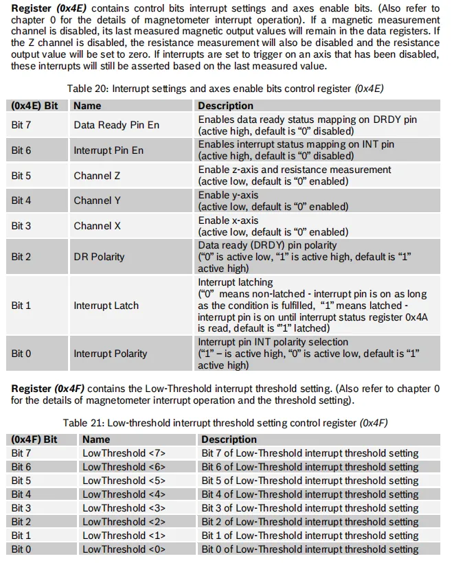
BMM150 Interrupt and Axis Enable Related Registers:
- Register
0x4Eis used to control axis enable and interrupt pin configuration: bits 7-6 respectively enable the interrupt mapping of theDRDYandINTpins, bits 5-3 control the three-axis measurement channels (active low, enabled by default), and bits 2-0 set theDRDYpolarity, interrupt latch mode, andINTpin polarity. - Register
0x4Fis a low threshold interrupt setting register, and its 8-bitLowThresholdis used to configure the low threshold trigger condition of the magnetic field data.
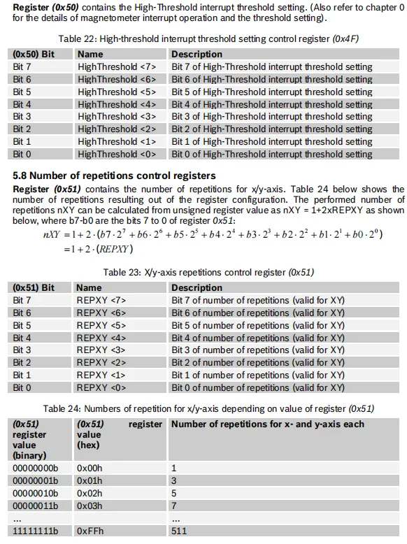
BMM150 High Threshold Interrupt and Repeat Count Control Register:
- Register
0x50is the high threshold interrupt setting register, which is 8 bits wide.The HighThresholdfield is used to configure the high threshold trigger condition for magnetic field data, and each bit corresponds to a different bit of the threshold. - Register
0x51is used to set the repetition count for X/Y axis measurement. The unsigned value of theREPXYfield is calculated via the formulanXY = 1 + 2×REPXY, with a range of 1 to 511 times; a higher count yields higher data precision but also increases power consumption.
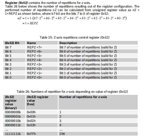
BMM150 Z -axis repetition control register (0x52) description: The register value REPZ calculates the nZ = 1 + REPZ Z -axis measurement repetition count via the formula, with a range of 1 to 256 times; each bit of the register corresponds to a binary bit of REPZ. A larger value yields higher data precision, but correspondingly increases power consumption and measurement duration.
2.8 PCB Routing Notes
None.
III. Circuit Engineering
3.1 Circuit Source Engineering
To obtain the source code of the circuit, please follow the official account [Freak Embedded]
3.2 Module Usage Instructions
The schematic diagram of this module is shown below:
SCH_Schematic1_3-Axis Geomagnetic Sensor Module Based on BMM150_v1.0.0_2026-05-12.pdf 2.2 MB
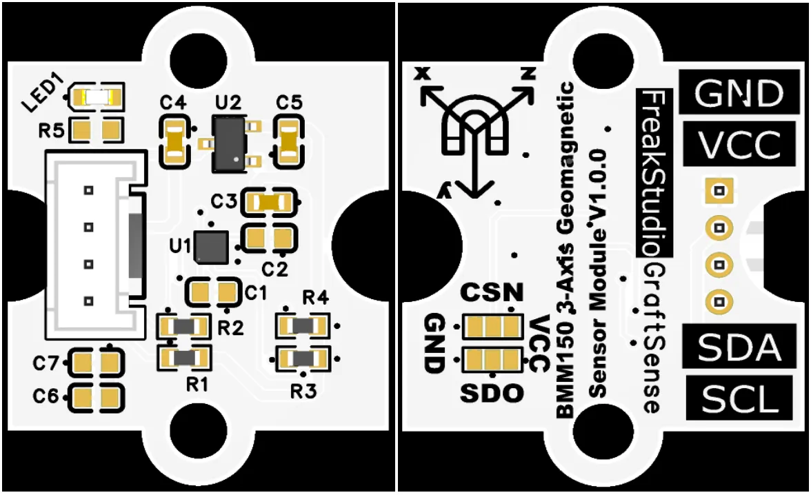
This module provides an IIC communication interface: it supports standard I2C communication rates, is compatible with 3.3V logic level, and can stably transmit the digital signals of three-axis magnetic field strength on the X / Y / Z axes collected by the BMM150. It is suitable for orientation and attitude detection scenarios of mobile phones, watches, drones and various portable devices, and provides the system with reliable data interaction capabilities for electronic compass and geomagnetic sensing.
By setting BMM150 CSB and SDO to the corresponding logic levels on their respective 3-pin shorting jumpers, the address for I2C communication can be configured as follows:
3.3 Application Experiment
Here, we use the GraftPort-RP2040 development board for testing, and the BMM150-based three-axis geomagnetic sensor module communicates with the main controller via the I2C interface.
Here, we first use the HY2.0-4P connection cable to connect the module to the GraftPort-RP2040 development board's I2C0 interface:
Development Board Pins | Module Pins | Description |
Pin 4 |
|
|
Pin 5 |
|
|
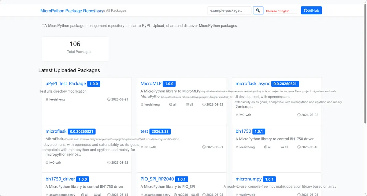
Here, we need to search for the relevant driver packages on uPyPI: https://upypi.net/zh/
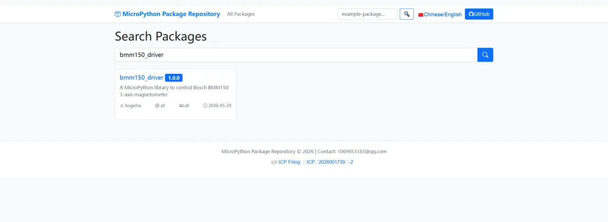
Enter bmm150_driver to search, and the following will be displayed:
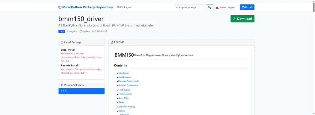
Click to copy the local installation command:
Import the module driver library code via the mip tool. Below are the usage commands for the mpremote tool:
mpremote mip install https://upypi.net/pkgs/bmm150_driver/1.0.0Import the 3-axis geomagnetic sensor module based on BMM150 - MicroPython driver code, then copy the following main.py code into our project:
# Python env   : MicroPython v1.23.0
# -*- coding: utf-8 -*-
# @Time    : 2023/01/01 00:00
# @Author  : Jose D. Montoya
# @File    : main.py
# @Description : Code to test the BMM150 three-axis magnetometer driver class
# @License : MIT

# ======================================== Import Modules =========================================
import time
from machine import Pin, I2C
from micropython_bmm150 import bmm150

# ======================================== Global Variables ============================================
# I2C configuration constants
I2C_BUS_ID = 0
I2C_SDA_PIN = 4
I2C_SCL_PIN = 5
I2C_FREQ = 400000

# BMM150 device constants
BMM150_DEVICE_ID_REG = 0xFF
BMM150_EXPECTED_ID = 0x32
BMM150_DEFAULT_ADDR = 0x13

# Print interval (ms)
print_interval = 500
last_print_time = 0

# ======================================== Functions ============================================
def test_basic_measurements():
    """
    Test basic magnetic field measurement function
    """
    print("=== Testing Basic Measurements ===")
    magx, magy, magz, hall = bmm.measurements
    print("X-axis: %d uT" % magx)
    print("Y-axis: %d uT" % magy)
    print("Z-axis: %d uT" % magz)
    print("Hall resistance: %d" % hall)
    print()


def test_operation_modes():
    """
    Test operating mode switching
    """
    print("=== Testing Operation Modes ===")
    # Test NORMAL mode
    bmm.operation_mode = bmm150.NORMAL
    print("Operation mode: %s" % bmm.operation_mode)
    time.sleep_ms(100)

    # Test FORCED mode
    bmm.operation_mode = bmm150.FORCED
    print("Operation mode: %s" % bmm.operation_mode)
    time.sleep_ms(100)

    # Restore NORMAL mode
    bmm.operation_mode = bmm150.NORMAL
    print("Restored to NORMAL mode")
    print()


def test_data_rates():
    """
    Test data rate configuration
    """
    print("=== Testing Data Rates ===")
    rates = [
        (bmm150.RATE_10HZ, "10Hz"),
        (bmm150.RATE_2HZ, "2Hz"),
        (bmm150.RATE_30HZ, "30Hz"),
    ]
    for rate_val, rate_name in rates:
        bmm.data_rate = rate_val
        print("Data rate set to: %s" % rate_name)
        print("Current data rate: %s" % bmm.data_rate)
        time.sleep_ms(100)
    print()


def test_thresholds():
    """
    Test threshold configuration
    """
    print("=== Testing Thresholds ===")
    # Test high threshold
    bmm.high_threshold = 100
    print("High threshold set to: %d" % bmm.high_threshold)

    # Test low threshold
    bmm.low_threshold = 50
    print("Low threshold set to: %d" % bmm.low_threshold)
    print()


def test_interrupt_mode():
    """
    Test interrupt mode configuration
    """
    print("=== Testing Interrupt Mode ===")
    # Enable interrupt
    bmm.interrupt_mode = bmm150.INT_ENABLED
    print("Interrupt mode: %s" % bmm.interrupt_mode)

    # Read interrupt status
    status = bmm.status_interrupt
    print("Interrupt status: %s" % str(status))
    print()


def print_continuous_data():
    """
    Continuously print magnetic field data (high-frequency function, for manual call from the REPL)
    """
    magx, magy, magz, hall = bmm.measurements
    print("X: %d uT, Y: %d uT, Z: %d uT, Hall: %d" % (magx, magy, magz, hall))
    status = bmm.status_interrupt
    print("Interrupt status: %s" % str(status))
    print()

# ======================================== Custom Classes ============================================

# ======================================== Initialization ==========================================
time.sleep(3)
print("FreakStudio: Testing BMM150 Magnetometer Driver ...")

# Initialize I2C bus
i2c = I2C(I2C_BUS_ID,sda=Pin(I2C_SDA_PIN), scl=Pin(I2C_SCL_PIN), freq=I2C_FREQ)

# Scan I2C devices
devices = i2c.scan()
if not devices:
    raise RuntimeError("No I2C devices found")
print("I2C devices found: %s" % [hex(addr) for addr in devices])

# Verify BMM150 device address
if BMM150_DEFAULT_ADDR not in devices:
    raise RuntimeError("BMM150 not found at address 0x%02X" % BMM150_DEFAULT_ADDR)
print("BMM150 found at address: 0x%02X" % BMM150_DEFAULT_ADDR)


# Initialize BMM150 driver
bmm = bmm150.BMM150(i2c,BMM150_DEFAULT_ADDR )
print("BMM150 driver initialized")
print()

# Run initialization test
test_basic_measurements()
test_operation_modes()
test_data_rates()
test_thresholds()
test_interrupt_mode()

print("=== Initialization tests completed ===")
print("Entering continuous monitoring mode...")
print()

# ========================================  Main Program  ===========================================
try:
    while True:
        current_time = time.ticks_ms()
        if time.ticks_diff(current_time, last_print_time) >= print_interval:
            # Low-frequency polling: print magnetic field data every 500ms
            magx, magy, magz, hall = bmm.measurements
            print("X: %d uT, Y: %d uT, Z: %d uT" % (magx, magy, magz))

            last_print_time = current_time

        # print_continuous_data()  # High-frequency function, commented out by default, can be called manually from the REPL
        time.sleep_ms(10)

except KeyboardInterrupt:
    print("Program interrupted by user")
except OSError as e:
    print("Hardware communication error: %s" % str(e))
except Exception as e:
    print("Unknown error: %s" % str(e))
finally:
    print("Cleaning up resources...")
    bmm.deinit()
    del bmm
    del i2c
    print("Program exited")
Burn the code, open the terminal, and the output is as follows:
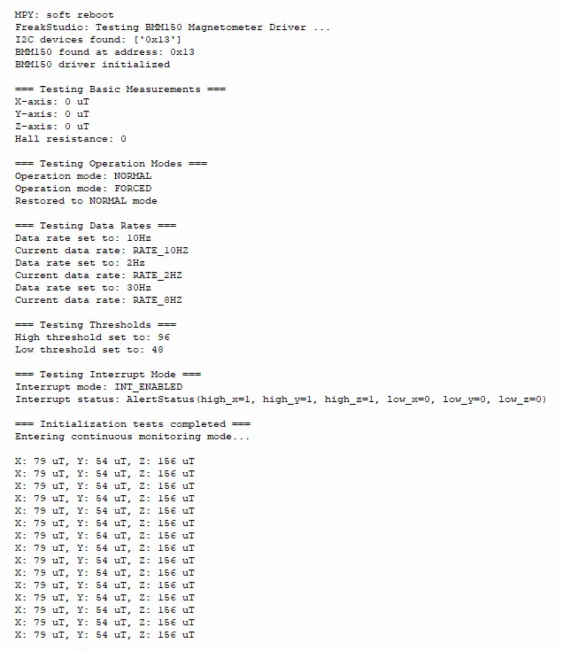
The BMM150 geomagnetic sensor is initialized properly and the I2C communication works normally. When the sensor is stationary, the three-axis geomagnetic readings remain stable while the low-threshold alarm keeps triggering; when the sensor is shaken, the three-axis geomagnetic readings fluctuate in real time with the attitude change, and the alarm status switches synchronously, indicating normal response.
IV. Drivers
bmm150_driver-1.0.0.zip 15 KB
5. BOM & Recommended Alternative Parts
None.
6. Revision History
Document Version | Date of Revision | Modifier | Modified Content |
v1.0 | 2026-05-12 | Ling Gaoxing | Initialize the document |
v1.1 | 2026-06-05 | Xin Ruili | Create an open version of the document, based on the internal document version v1.1. |
VII. Relevant Materials
7.1 Chip Datasheet
BMM150.pdf 1.2 MB
7.2 Unique Icons for PCB Silk Screen