Contents
- I. Module Introduction
- II. Introduction to Major Chips
- 2.1 Chip Overview
- 2.2 Pin Definition
- 2.3 Functional Block Diagram
- 2.4 Performance Parameters
- 2.5 Reference Circuit
- 2.6 Chip Configuration
- 2.7 Communication Interfaces and Related Protocols
- 2.8 PCB Routing Precautions
- III. Circuit Engineering
- 3.1 Circuit Source Engineering
- 3.2 Module Usage Instructions
- 3.3 Application Experiment
- 4. Drivers
- 5. BOM & Recommended Alternative Parts
- VI. Revision History
- VII. Relevant Materials
- 7.1 Chip Datasheet
- 7.2 PCB Silkscreen Specific Icons
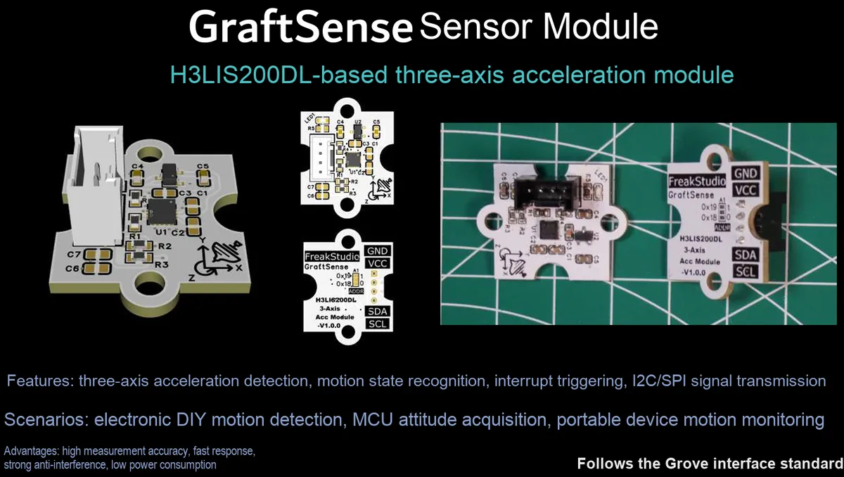
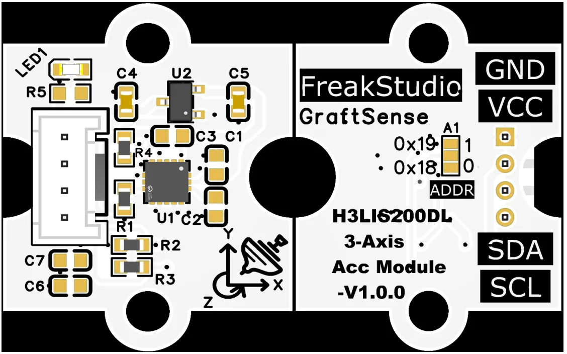
I. Module Introduction
Tri-axis acceleration module based on H3LIS200DL, adopts H3LIS200DL high-range Acceleration Sensor, supports configurable ranges of ±100g/±200g, has a built-in 12-bit ADC, with a minimum resolution of 49mg/digit, capable of accurately capturing drastic acceleration changes;The module has a built-in 5V to 3.3V power supply circuit, compatible with 3.3V logic level MCU, and is equipped with I²C pull-up resistors and power supply decoupling capacitors. Users can select between two ADDR jumper points to configure 0x18 / 0x19 as the I²C address. It also features ultra-low power consumption (operating current is only 1mA, and as low as 2μA in power-down mode), making it ideal for shock detection, motion monitoring, and battery-powered embedded applications.
II. Introduction to Major Chips
H3LIS200DL is a high-range ultra-low-power three-axis Acceleration Sensor that supports ±100g/±200g measurement ranges, has a built-in 12-bit ADC, features a minimum resolution of 49mg/digit, draws only 1mA operating current and as low as 2μA in power-down mode, communicates via the I²C interface, and is suitable for shock detection and battery-powered applications.
2.1 Chip Overview
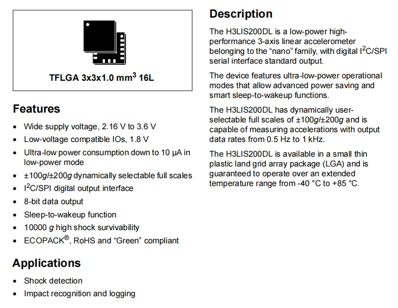
H3LIS200DL is an ultra-low-power high-range three-axis Acceleration Sensor that supports dynamic range selection of ±100g/±200g, adopts the I²C interface, features sleep wake-up function and 10000g impact resistance, and is suitable for impact detection and collision recognition scenarios.
2.2 Pin Definition
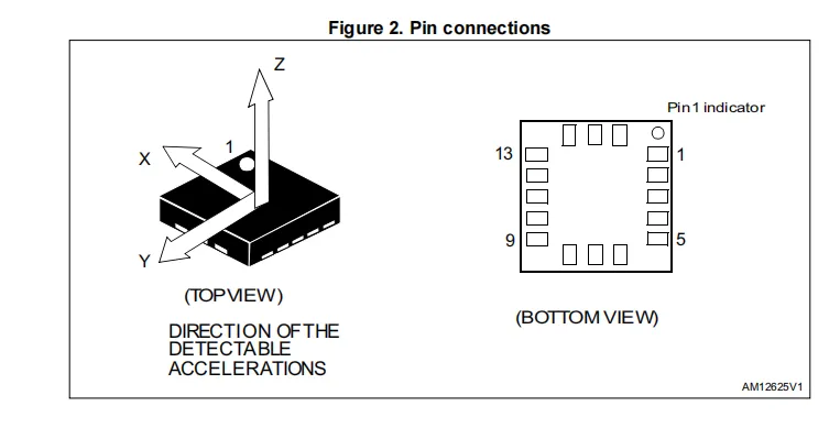
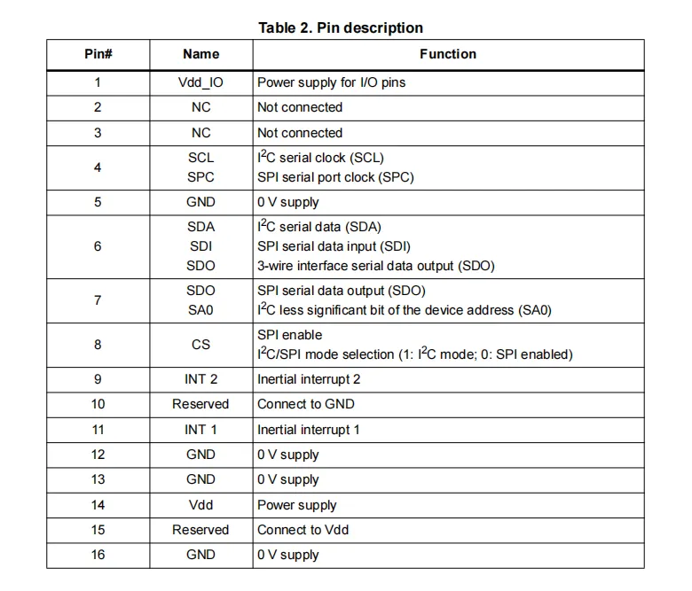
H3LIS200DL adopts a 16-pin LGA package, whose pins are clearly divided into power supply (Vdd / Vdd_IO), ground (GND), communication interface (I²C / SPI shared) and interrupt pins (INT1 / INT2). It also supports configuring the I²C address and communication mode via the SA0 and CS pins, adapting to the requirements of miniaturized and flexible circuit design.
2.3 Functional Block Diagram
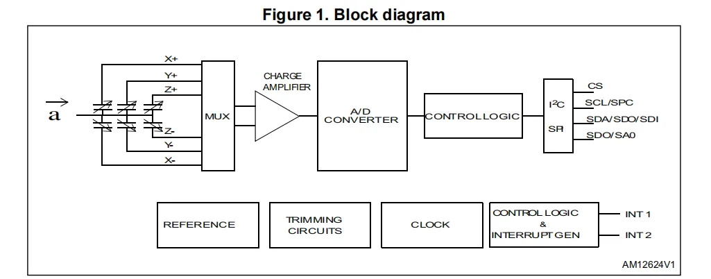
H3LIS200DL has a functional block diagram centered on a three-axis capacitive sensing unit: the acceleration signal undergoes multiplexing, charge amplification and analog-to-digital conversion, then is processed by the control logic, and output via the I²C / SPI interface; meanwhile, it integrates reference, calibration, clock and interrupt generation modules to realize high-range, low-power acceleration detection.
2.4 Performance Parameters
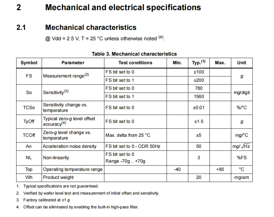
H3LIS200DL supports ±100g/±200g measurement ranges, with corresponding sensitivities of 780/1560 mg/digit, a typical 0g offset of ±1.5g, a temperature drift of ±5 mg/℃, and a non-linearity of ≤3% FS, an operating temperature range of -40℃ to + 85℃, featuring a high measurement range and stable temperature characteristics.
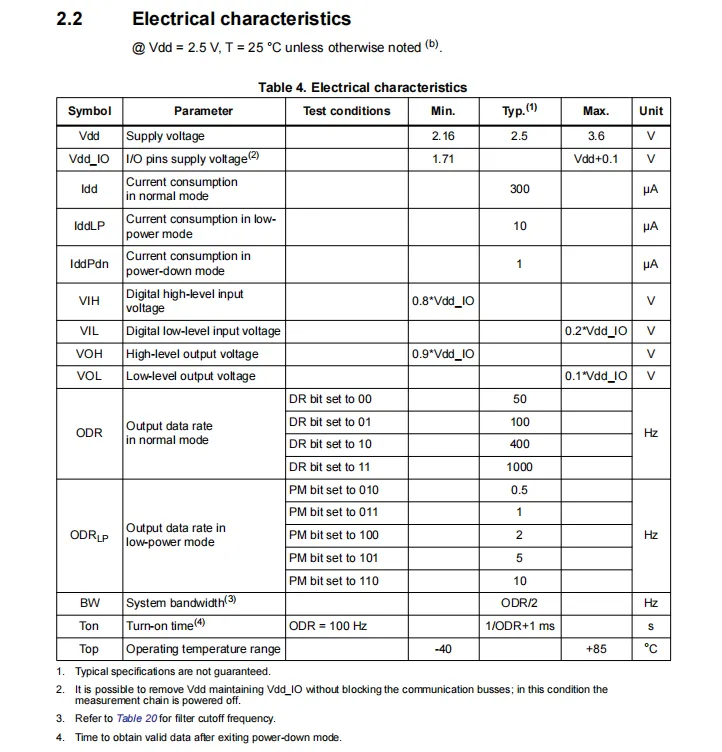
H3LIS200DL operates at a supply voltage of 2.16~3.6V, with a typical current consumption of 300μA in normal mode, 10μA in low-power mode, and merely 1μA in power-down mode; its output data rate is adjustable from 0.5 to 1000Hz, I/O is compatible with voltages above 1.71V, and it works within a temperature range of -40°C to + 85°C, featuring ultra-low power consumption and wide voltage adaptability.
2.5 Reference Circuit
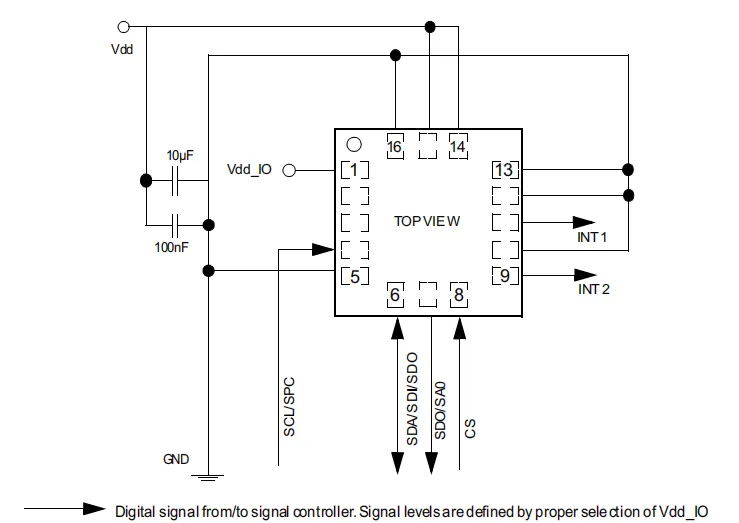
This is a typical application circuit for H3LIS200DL, which ensures stable power supply through a decoupling capacitor, leads out the I²C / SPI communication interface and interrupt pin, and is suitable for low-power embedded impact detection scenarios.
2.6 Chip Configuration
None.
2.7 Communication Interfaces and Related Protocols
H3LIS200DL operates as an I²C slave, communicating via the SCL (clock) line and SDA (bidirectional data) line; it features built-in pull-up resistors, is compatible with standard/fast mode (up to 400kHz), and supports register read/write operations as well as data exchange.
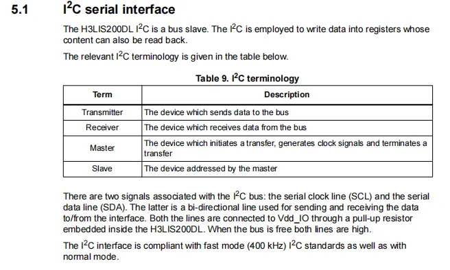
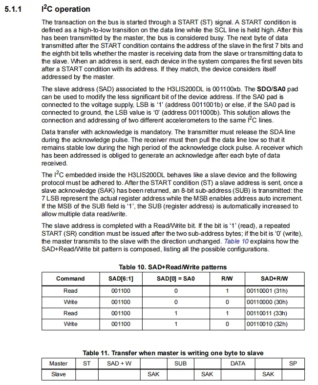
H3LIS200DL operates as an I²C slave with the slave address 001100xb (SA0 connected to GND corresponds to 0x30 / 0x31, while connected to VDD corresponds to 0x32 / 0x33). It supports automatic increment of register addresses, and the communication sequence of Start → Address → Acknowledge → Subaddress → Acknowledge → Data → Acknowledge → Stop must be strictly followed; an acknowledge is mandatory after each byte transmission.
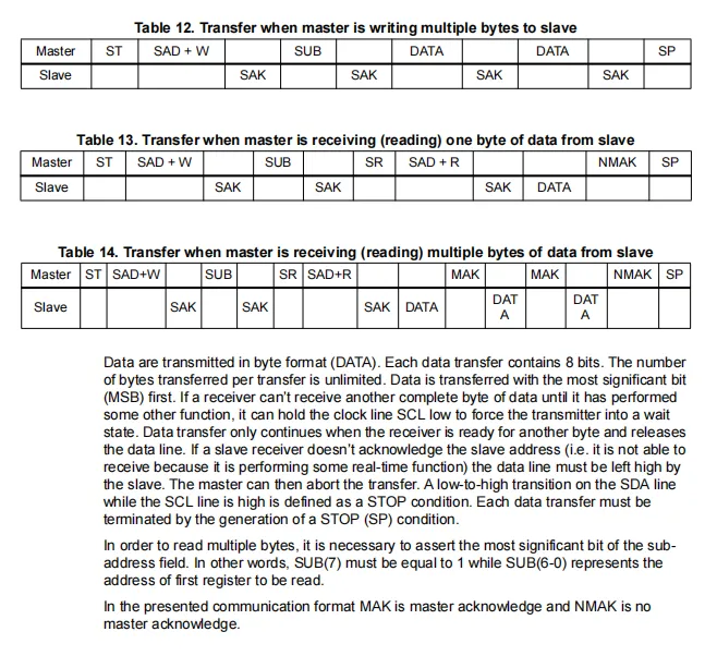
H3LIS200DL supports I²C communication with single/multi-byte read and write capabilities. The write operation sequence is: Start → Address + Write → Subaddress → Data →. .. → Stop. For read operations, the subaddress must be written first, followed by a repeated Start → Address + Read. For multi-byte reads, the most significant bit of the subaddress must be set to 1. An acknowledgment is required after each byte transmission, and the operation ends with a NACK followed by a Stop condition.
2.8 PCB Routing Precautions
None.
III. Circuit Engineering
3.1 Circuit Source Engineering
To obtain the circuit source project, please follow the official account [Freak Embedded].
3.2 Module Usage Instructions
The schematic diagram of this module is shown below:
SCH_3-Axis Accelerometer Module Based on H3LIS200DL-V1.0.0_2026-03-25.pdf 2.2 MB
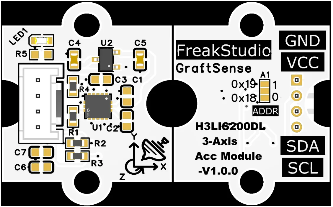
This module provides an I²C communication interface: it supports standard/fast mode I²C communication (max. 400kHz), and two ADDR strap options allow selection between 0x18 / 0x19 as the I²C address. It is 3.3V logic compatible, capable of stably implementing read and write operations for high-range 3-axis acceleration data and configuration registers. Suitable for impact detection, motion monitoring, and battery-powered embedded low-power scenarios, it delivers reliable high-magnitude acceleration acquisition and interaction capabilities for the system.
3.3 Application Experiment
Here, we use the GraftPort-RP2040 development board for testing, and the triaxial acceleration module based on the H3LIS200DL uses the I2C interface to communicate with the main controller.
Here, we first use the HY2.0-4P cable to connect the module to the GraftPort-RP2040 development board's I2C0 interface:
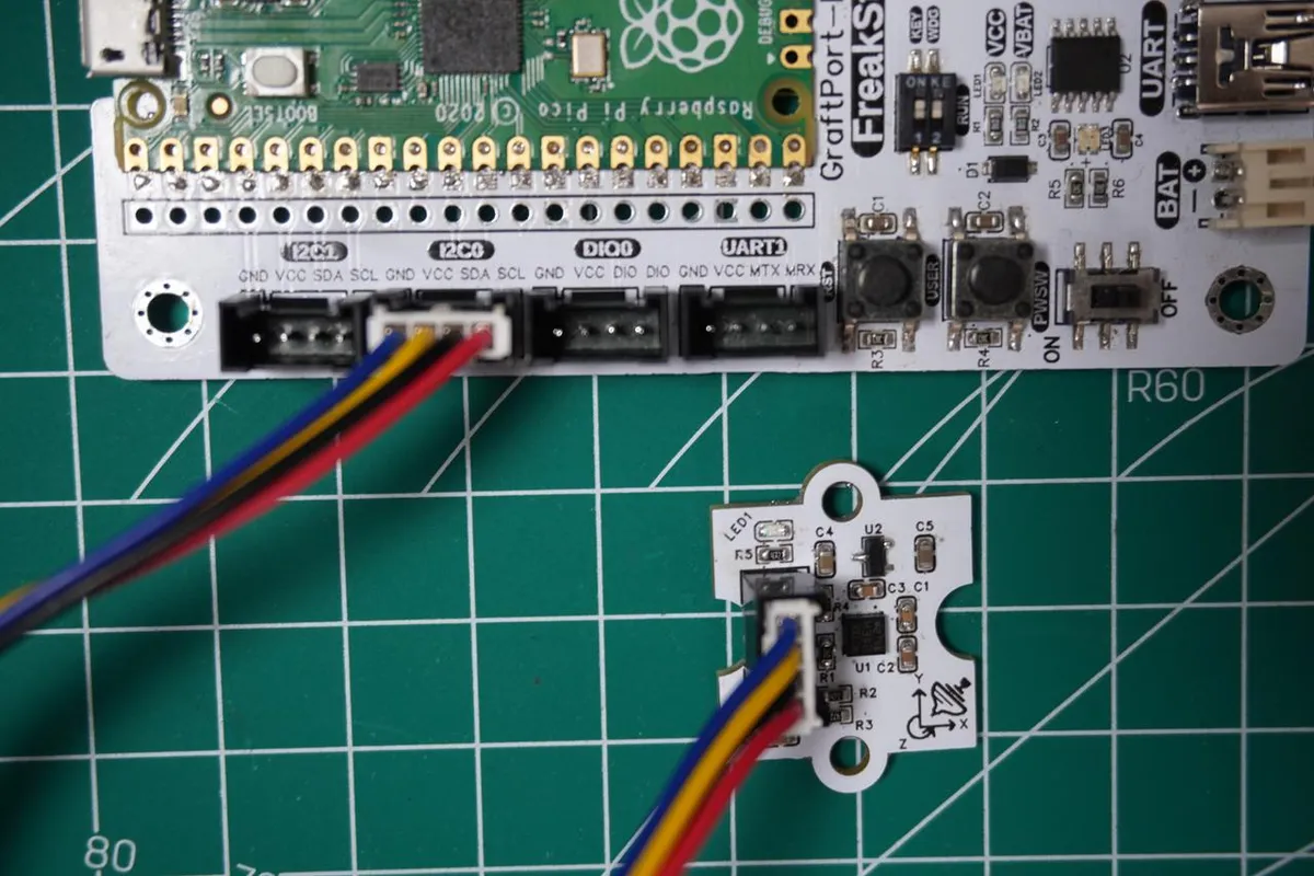
The module connections are shown in the following table:
Development Board Pins | Module Pins | Description |
Pin 4 |
|
|
Pin 5 |
|
|
Here, we need to search for the relevant driver packages on uPyPI: https://upypi.net/zh/
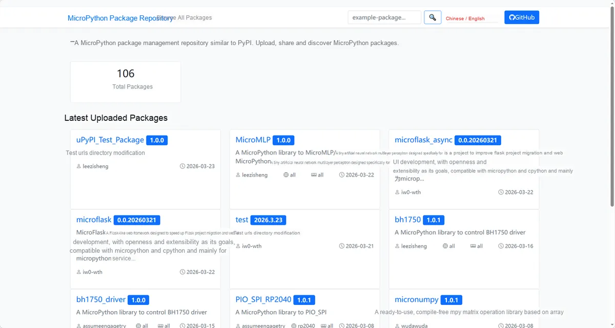
Enter h3lis200dl_driver to search, and the following will be displayed:
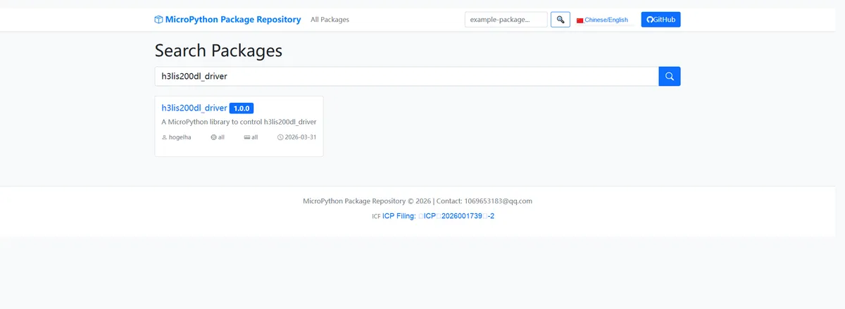
Click to copy the local installation command:
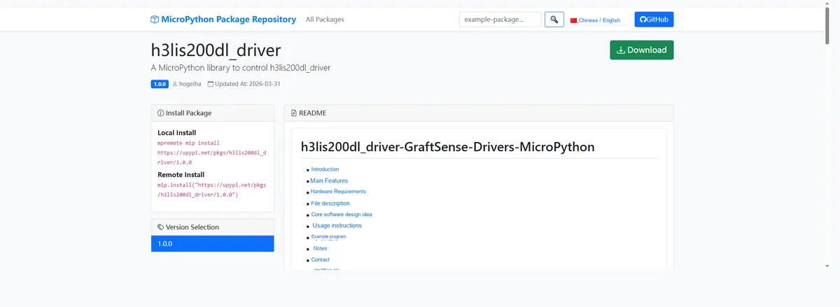
Import the module driver library code via the mip tool. Below are the usage commands for the mpremote tool:
mpremote mip install https://upypi.net/pkgs/h3lis200dl_driver/1.0.0Import the 3-axis acceleration module based on H3LIS200DL - MicroPython driver code, then copy the following main.py code into our project:
# Python env   : MicroPython v1.23.0
# -*- coding: utf-8 -*-
# @Time    : 2026/3/27 8:45 PM

# @Author  : Jose D. Montoya
# @File    : main.py
# @Description : H3LIS200DL accelerometer data reading program

# ======================================== Import Modules =========================================
import time
from machine import Pin, I2C
from micropython_h3lis200dl import h3lis200dl

# ======================================== Global Variables ============================================
# Define target sensor I2C address list
TARGET_H3LIS200DL_ADDRS = [0x18, 0x19]

# ======================================== Functions ============================================


# ======================================== Custom Classes ============================================


# ======================================== Initialization configuration ===========================================
time.sleep(3)
print("FreakStudio: H3LIS200DL accelerometer initialization")

# Initialize the I2C bus
i2c_bus = I2C(0, sda=Pin(4), scl=Pin(5), freq=400000)

# Scan all devices on the I2C bus
devices_list: list[int] = i2c_bus.scan()
print("START I2C SCANNER")

# Check whether any I2C device was found
if len(devices_list) == 0:
    print("No i2c device !")
    raise SystemExit("I2C scan found no devices, program exited")
else:
    print("i2c devices found:", len(devices_list))

# Placeholder for the sensor object
sensor = None

# Iterate through the device list to match the sensor address
for device in devices_list:
    if device in TARGET_H3LIS200DL_ADDRS:
        print("I2c hexadecimal address:", hex(device))
        try:
            # Initialize the sensor
            sensor = h3lis200dl.H3LIS200DL(i2c_bus)
            print("Sensor initialization successful")
            break
        except Exception as e:
            print(f"Sensor Initialization failed: {e}")
            continue
else:
    # Target sensor not found
    raise Exception("No target sensor device found in I2C bus")

# ========================================  Main Program  ============================================
while True:
    # Get three-axis acceleration data
    accx, accy, accz = sensor.acceleration
    # Print formatted acceleration data
    print(f"x:{accx:.2f}g, y:{accy:.2f}g, z:{accz:.2f}g")
    print()
    # Delay 0.5 seconds
    time.sleep(0.5)
Burn the code, open the terminal, and the output is as follows:
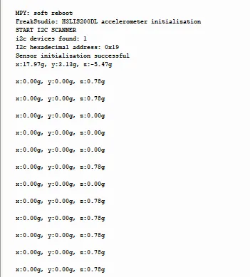
We can see that the three-axis acceleration values are printed in a loop.
4. Drivers
h3lis200dl_driver-1.0.0.zip 14 KB
5. BOM & Recommended Alternative Parts
None.
VI. Revision History
Document Version | Date of Revision | Modifier | Modify Content |
v1.0 | 2026-03-25 | Ling Gaoxing | Initialize the document |
v1.0.1 | 2026-04-05 | Li Zisheng | No photos for the homepage have been taken, the production files have not been exported yet, and all other items have been sorted out. |
v1.0.2 | 2026-04-21 | Li Zisheng | The production documents have not been exported yet, while all the rest have been sorted out. |
v1.1 | 2026-04-23 | Xin Ruili | Create an open version of the document, based on the internal document version v1.0.2. |
VII. Relevant Materials
7.1 Chip Datasheet
H3LIS200DL.pdf 661 KB
7.2 PCB Silkscreen Specific Icons