Contents
- I. Module Introduction
- II. Introduction to Major Chips
- 2.1 Chip Overview
- 2.2 Pin Definition
- 2.3 Functional Block Diagram
- 2.4 Performance Parameters
- 2.5 Reference Circuit
- 2.6 Chip Configuration
- 2.7 Communication Interfaces and Related Protocols
- 2.8 PCB Routing Precautions
- III. Circuit Engineering
- 3.1 Circuit Source Engineering
- 3.2 Module Usage Instructions
- 3.3 Application Experiment
- 4. Drivers
- 5. BOM & Recommended Alternative Parts
- VI. Revision History
- VII. Relevant Materials
- 7.1 Chip Datasheet
- 7.2 PCB Silkscreen Specific Icons
I. Module Introduction
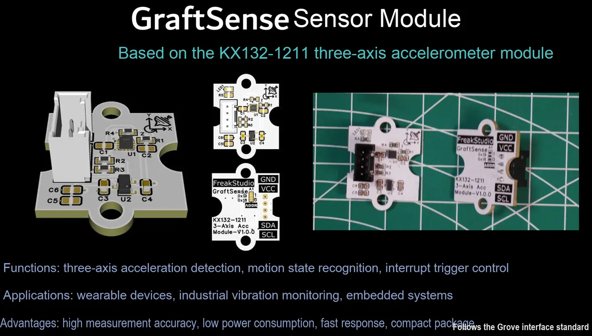
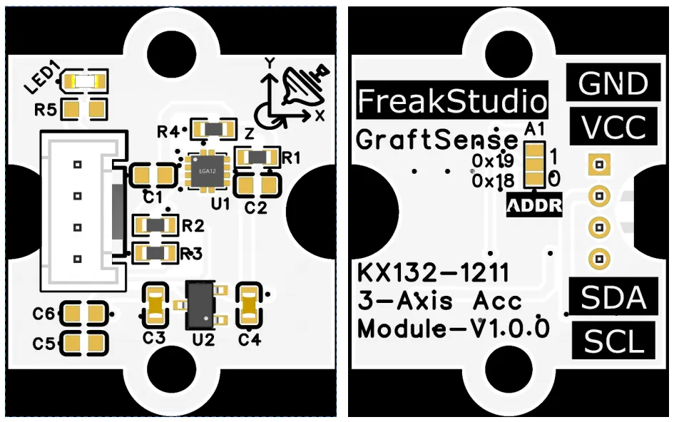
Tri-axis acceleration module based on KX132-1211, which adopts the KX132-1211 16-bit tri-axis Acceleration Sensor, supports configurable measurement ranges of ±2g/±4g/±8g/±16g, communicates via the I²C interface, and has built-in interrupt and FIFO functions to realize vibration detection, tilt detection and low-power wake-up;The module has a built-in 5V-to-3.3V power supply circuit, which is compatible with 3.3V level MCU, and is equipped with I²C pull-up resistors and power supply decoupling capacitors. Users can select between ADDR levels to configure either of the two 0x18 / 0x19 I²C addresses, making it suitable for scenarios such as attitude sensing, motion monitoring, and embedded low-power interaction.
II. Introduction to Major Chips
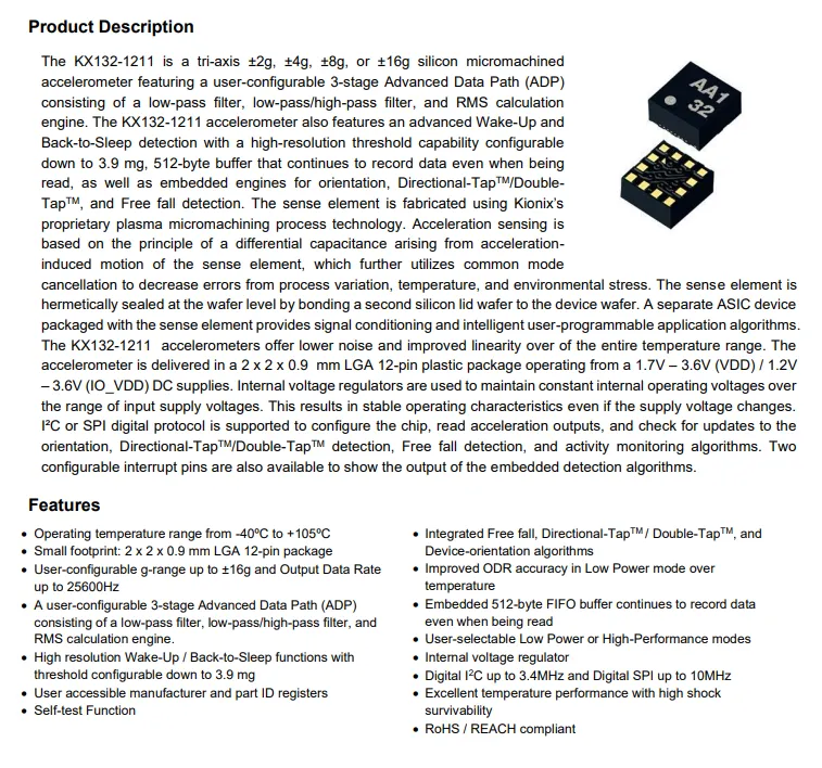
KX132-1211 is a 16-bit high-precision three-axis Acceleration Sensor that supports configurable measurement ranges of ±2g/±4g/±8g/±16g, communicates via the I²C interface, and has built-in interrupt and FIFO functions. It can realize vibration and tilt detection as well as low-power wake-up, and is suitable for posture sensing and motion monitoring scenarios.
2.1 Chip Overview
KX132-1211 is a 16-bit 3-axis capacitive MEMS Acceleration Sensor that supports a measurement range of ±2g to ±16g and a maximum ODR of 25600Hz. It has built-in 3-level ADP filtering, a 512-byte FIFO, and wake-up/tap/free fall detection algorithms. It features an I²C interface, low power consumption and high impact resistance, making it suitable for high-precision motion monitoring scenarios.
2.2 Pin Definition
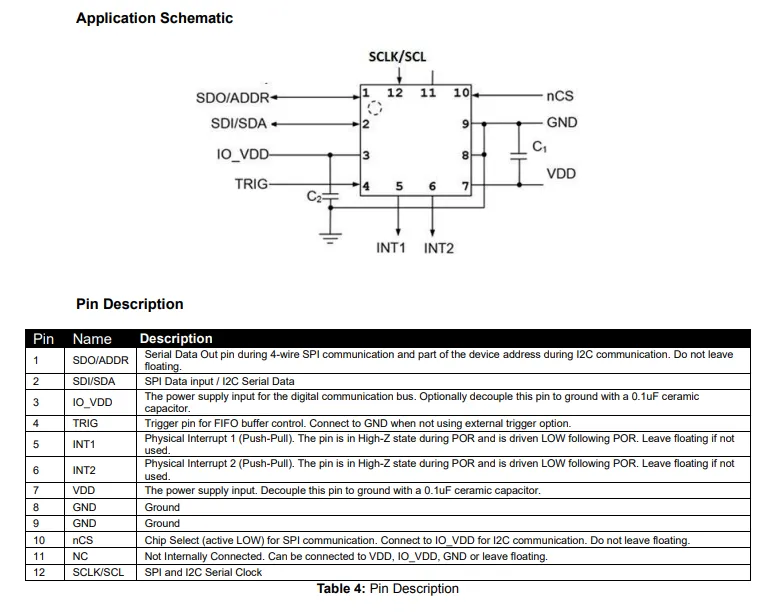
KX132-1211 adopts a 12-pin LGA package with clearly defined pin functions:
- Power Supply and Ground:
VDDis the core power supply (a 0.1μF decoupling capacitor shall be connected nearby),IO_VDDis the digital I/O power supply (a 0.1μF capacitor can be connected for decoupling), and pins 8 and 9 are common ground; - Communication Interface: Supports
I²C/SPIdual modes.SCL/SCLKserves as the clock pin;SDI/SDAserves as the data input / bidirectional data pin;SDO/ADDRacts as the data output pin inSPImode and as the address bit inI²Cmode;nCSis theSPIchip select pin (connected toI²Cwhen inIO_VDDmode); - Functions and Interrupts:
TRIGis theFIFOtrigger pin (connect to ground when not in use),INT1/INT2are two push-pull interrupt output pins (leave floating when not in use), Pin 11 is anNC(no connection) pin which can be left floating or connected to power supply / ground.
2.3 Functional Block Diagram
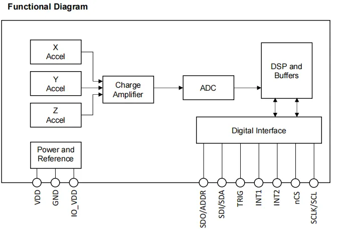
KX132-1211 has a functional block diagram centered on a three-axis capacitive acceleration sensing unit: the acceleration signals of the X and Y and Z axes are converted into voltage signals via a charge amplifier, then digitized by an ADC; after being processed by a DSP and buffered, the digital signals are output through digital interfaces (I²C / SPI), with support for interrupt and FIFO trigger control; the power and reference module supplies power to the entire chip, realizing high-precision acceleration acquisition and intelligent motion detection as a whole.
2.4 Performance Parameters
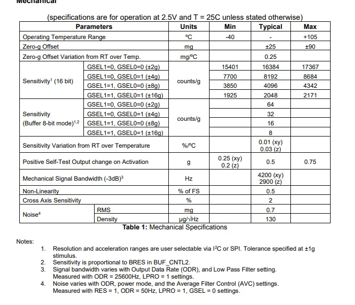
KX132-1211 has the following mechanical property parameters:
- Operating temperature range: -40℃ to + 105℃, typical 0g offset: ±25mg, typical temperature drift: 0.25mg/℃;
- Sensitivity in 16-bit mode is adjustable with the measurement range (typically 16384 counts/g at ±2g, typically 2048 counts/g at ±16g), while the sensitivity in 8-bit buffer mode corresponds to 64~8 counts/g;
- Sensitivity temperature drift Typical: 0.01%/℃(xy-axis) / 0.03%/℃(z-axis); mechanical bandwidth: 4200Hz for xy-axis, 2900Hz for z-axis; nonlinearity ≤0.5% FS; cross-axis sensitivity: 2%; typical RMS noise: 0.7mg, featuring high precision and stable temperature characteristics as a whole.
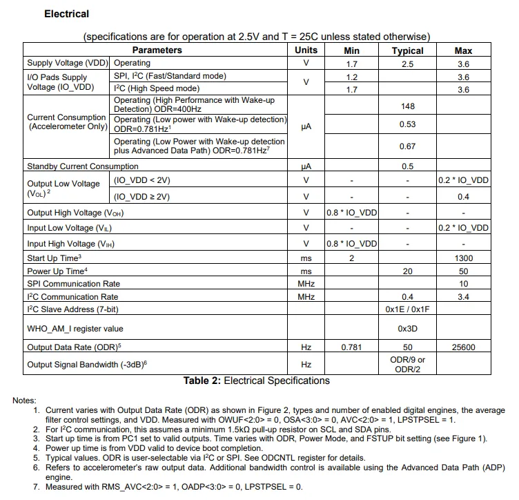
KX132-1211 Electrical parameters: Operating voltage VDD ranges from 1.7V to 3.6V, IO_VDD ranges from 1.2V to 3.6V; power consumption varies by mode, and only 0.53μA in wake-up detection mode. Electrical interfaces are compatible with I²C (0.4~3.4MHz) and SPI (1~10MHz);I²C slave addresses are 0x1E / 0x1F, and WHO_AM_I value is 0x3D;Output Data Rate ODR ranges from 0.781 Hz to 25600 Hz, with a maximum bandwidth of 1/2 of the ODR, a maximum power-on startup time of 1.3 ms, and overall features of wide voltage adaptation, high-speed communication and low power consumption.
2.5 Reference Circuit
None.
2.6 Chip Configuration
None.
2.7 Communication Interfaces and Related Protocols
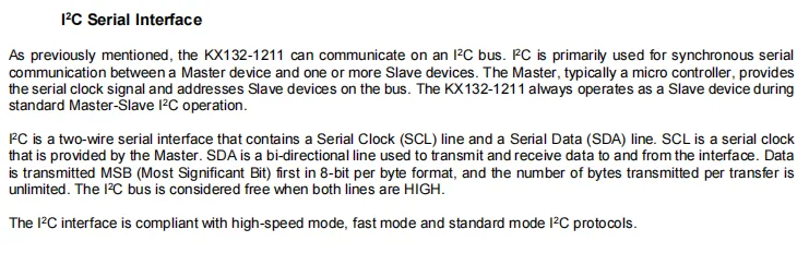
KX132-1211 serves as an I²C slave and communicates via two wires: SCL (clock provided by the master) and SDA (bidirectional data). Data is transmitted in an 8-bit MSB -first format, compatible with high-speed, fast and standard I²C protocols. When the bus is idle, both SCL and SDA are at a high level.
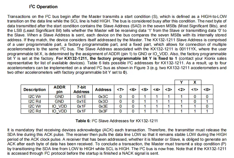
I²C communication starts with a master-initiated Start condition (S), followed by the transmission of a 7-bit slave address plus a read/write bit; the slave address of KX132-1211 is determined by the level of the ADDR pin (connected to GND for 0x1E, connected to IO_VDD for 0x1F) and factory-programmable bits, allowing up to 4 devices to be connected to the same bus; an acknowledge (ACK) is required after each byte transmission, and the communication is terminated by the master sending a Stop condition (P).
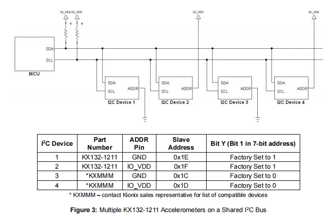
Typical connection for multi-device sharing of the I²C bus: MCU acts as the host, and pull-up resistors shall be connected to SDA / SCL; by configuring the level of the ADDR pin, multiple KX132-1211 (or compatible devices) can be assigned different slave addresses to realize multi-sensor networking.
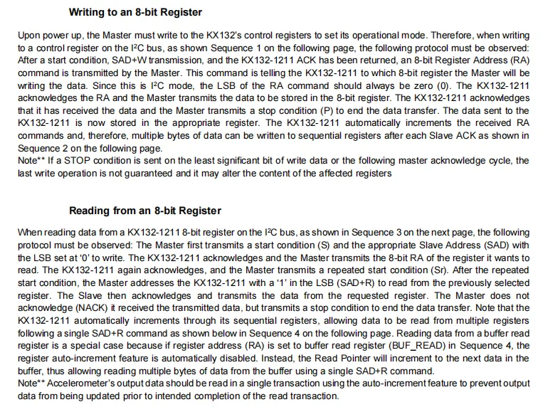
Write Register: The master sends a start condition → slave address + write bit → register address (RA) → data → stop condition, and supports multi-byte consecutive writing (with automatic register address increment).
Register Read: The host first writes the register address, then sends a repeated start condition + slave address + read bit, subsequently reads data (single-byte / multi-byte), and finally terminates with NACK + stop condition; when reading the buffer register, the auto-increment function of the address will be disabled.
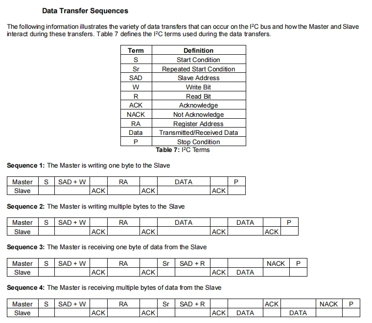
This diagram defines the I²C core timing sequence for communication, clearly specifying the interaction and response logic between the master and slave devices at each stage.
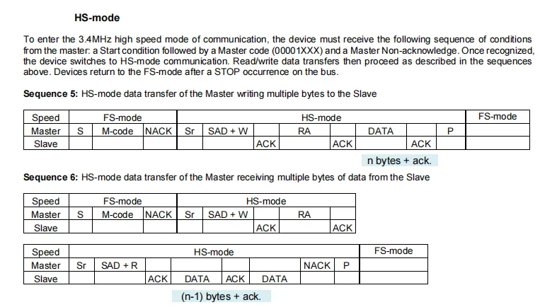
3.4MHz High-Speed Mode (HS - mode): The master must first send a start condition + master code + NACK to enter HS mode. Its read/write timing is consistent with that of the standard mode, and the bus automatically reverts to fast/standard mode after receiving a stop condition; meanwhile, a complete timing sequence for multi-byte read and write in HS mode is provided.
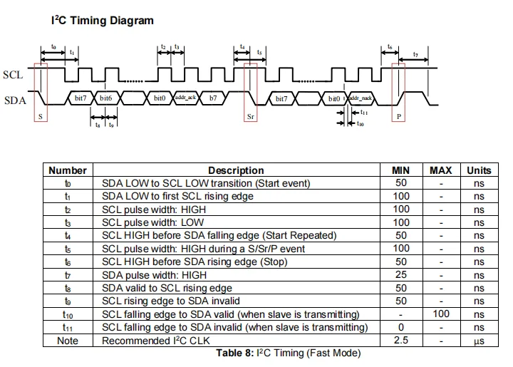
KX132-1211 I²C Fast Mode Timing Requirements: SDA and SCL shall meet strict setup/hold time requirements. For example, in a start condition, the delay from SDA falling to SCL falling shall be at least 50ns, and the delay from SDA falling to the first SCL rising edge shall be at least 100ns;SCL high and low pulse widths shall both be ≥100ns, and data setup/hold times shall be ≥50ns respectively;During slave transmission, SCL falling edge to SDA valid is max 100ns, to SDA invalid is min 0ns. A recommended I²C clock cycle of 2.5μS enables stable high-speed communication.
2.8 PCB Routing Precautions
None.
III. Circuit Engineering
3.1 Circuit Source Engineering
To obtain the circuit source project, please follow the official account [Freak Embedded].
3.2 Module Usage Instructions
The schematic diagram of this module is shown below:
SCH_3-Axis Accelerometer Module Based on KX132-1211-V1.0.0_2026-03-25.pdf 2.3 MB
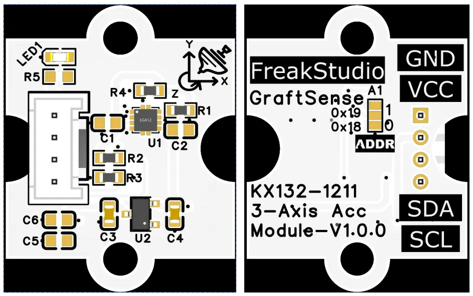
This module provides an I²C communication interface: it supports standard / fast / high-speed I²C communication rates (up to 3.4MHz), and two ADDR jumper-selectable 0x18 / 0x19 I²C addresses. It is compatible with 3.3V logic level, and can stably implement reading and writing of 16-bit three-axis acceleration data and configuration registers as well as interrupt notification. It is applicable to scenarios such as attitude sensing, motion monitoring and embedded low-power interaction, providing the system with reliable high-precision motion Data Acquisition and interaction capabilities.
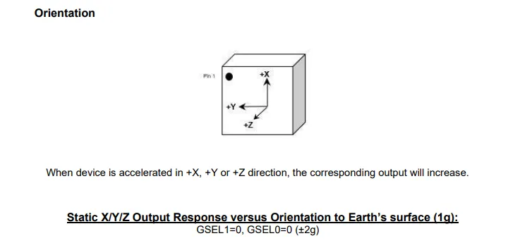
The azimuth diagram of the gyroscope is shown as follows:
3.3 Application Experiment
Here, we use the GraftPort-RP2040 development board for testing, and the three-axis acceleration module based on KX132-1211 uses the I2C interface to communicate with the main controller.
Here, we first use the HY2.0-4P cable to connect the module to the GraftPort-RP2040 development board's I2C0 interface:
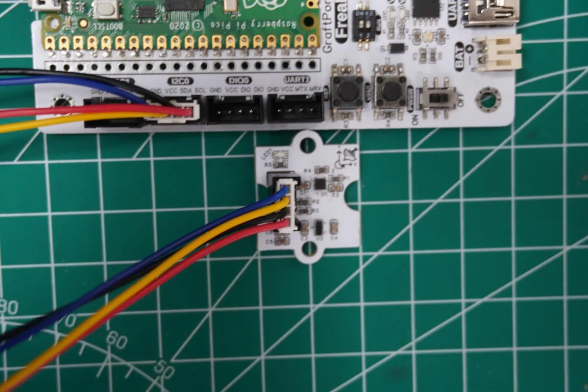
The module connections are shown in the following table:
Development Board Pins | Module Pins | Description |
Pin 4 |
|
|
Pin 5 |
|
|
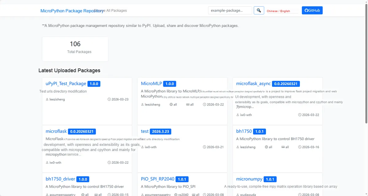
Here, we need to search for the relevant driver packages on uPyPI: https://upypi.net/zh/
Enter kx132_driver to search, and the following will be displayed:
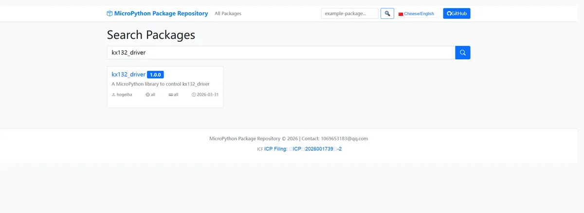
Click to copy the local installation command:
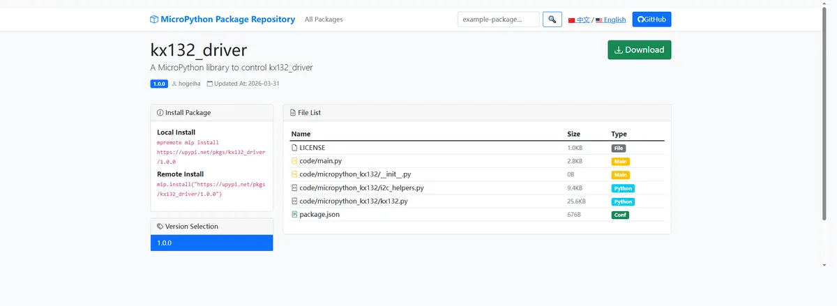
Import the module driver library code via the mip tool. Below are the usage commands for the mpremote tool:
mpremote mip install https://upypi.net/pkgs/kx132_driver/1.0.0Import the 3-axis acceleration module based on KX132-1211 - MicroPython driver code, then copy the following main.py code into our project:
# Python env   : MicroPython v1.23.0
# -*- coding: utf-8 -*-
# @Time    : 2026/3/23 4:23 PM
# @Author  : Jose D. Montoya
# @File    : main.py
# @Description : Read the three-axis acceleration data of the KX132 accelerometer and print it in real time

# ======================================== Import Modules =========================================

# Import the time module to implement delays
import time

# Import the Pin and I2C modules for hardware pin and I2C communication configuration
from machine import Pin, I2C

# Import the kx132 module to operate the KX132 accelerometer
from micropython_kx132 import kx132

# ======================================== Global Variables ============================================

# Define I2C communication constants (for Raspberry Pi Pico)
I2C_SCL_PIN = 5  # I2C clock pin
I2C_SDA_PIN = 4  # I2C data pin
I2C_FREQ = 400000  # I2C communication frequency (400KHz, supported by KX132)
TARGET_SENSOR_ADDR = 0x1F  # Default I2C address of the KX132 accelerometer (can also be changed to 0x1E depending on hardware configuration)
kx = None  # Sensor object initialized to None

# ======================================== Functions ============================================

# ======================================== Custom Classes ============================================

# ======================================== Initialization configuration ===========================================

# System startup delay of 3 s to ensure the sensor finishes initialization
time.sleep(3)
# Print initialization complete message
print("FreakStudio: Read KX132 acceleration data")

# Initialize the I2C bus
i2c_bus = I2C(0, scl=Pin(I2C_SCL_PIN), sda=Pin(I2C_SDA_PIN), freq=I2C_FREQ)
# Start scanning for devices on the I2C bus
devices_list: list[int] = i2c_bus.scan()
print("START I2C SCANNER")

# Check the I2C device scan result
if len(devices_list) == 0:
    print("No i2c device !")
    raise SystemExit("I2C scan found no devices, program exited")
else:
    print("i2c devices found:", len(devices_list))

# Iterate over the address list to initialize the target sensor
for device in devices_list:
    if device == TARGET_SENSOR_ADDR:
        print("I2c hexadecimal address:", hex(device))
        try:
            kx = kx132.KX132(i2c=i2c_bus)
            print("Target sensor initialization successful")
            break
        except Exception as e:
            print(f"Sensor Initialization failed: {e}")
            continue
else:
    raise Exception("No KX132 sensor found")


# ========================================  Main Program  ============================================

# Read and print acceleration data in an infinite loop
while True:
    # Read the sensor's three-axis acceleration data (x, y, z axes)
    accx, accy, accz = kx.acceleration
    # Print the formatted three-axis acceleration data, two decimal places, unit g
    print(f"x:{accx:.2f}g, y:{accy:.2f}g, z:{accz:.2f}g")
    # Print a blank line to tidy the output format
    print()
    # Delay 0.1 s to control the data print frequency
    time.sleep(0.1)
Burn the code, open the terminal, and the output is as follows:
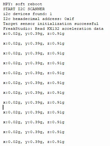
It can be seen that the values of the three-axis acceleration are printed cyclically.
4. Drivers
kx132_driver-1.0.0.zip 11 KB
5. BOM & Recommended Alternative Parts
None.
VI. Revision History
Document Version | Date of Revision | Modifier | Modify Content |
v1.0 | 2026-03-25 | Ling Gaoxing | Initialize the document |
v1.0.1 | 2026-04-05 | Li Zisheng | No photos for the homepage have been taken, the production files have not been exported yet, and all other items have been sorted out. |
v1.0.2 | 2026-04-14 | Li Zisheng | Modified main.py. |
v1.0.3 | 2026-04-21 | Li Zisheng | The production documents have not been exported yet, while all the rest have been sorted out. |
v1.1 | 2026-04-23 | Xin Ruili | Create an open version of the document, based on the internal document version v1.0.3. |
VII. Relevant Materials
7.1 Chip Datasheet
KX132-1211.pdf 1.1 MB
7.2 PCB Silkscreen Specific Icons