Contents
- I. Module Introduction
- II. Introduction to Major Chips
- 2.1 Chip Overview
- 2.2 Pin Definition
- 2.3 Functional Block Diagram
- 2.4 Performance Parameters
- 2.5 Reference Circuit
- 2.6 Chip Configuration
- 2.7 Communication Interfaces and Related Protocols
- 2.8 PCB Routing Precautions
- III. Circuit Engineering
- 3.1 Circuit Source Engineering
- 3.2 Module Usage Instructions
- 3.3 Application Experiment
- 4. Drivers
- 5. BOM & Recommended Alternative Parts
- VI. Revision History
- VII. Relevant Materials
- 7.1 Chip Datasheet
- 7.2 PCB Silkscreen Specific Icons
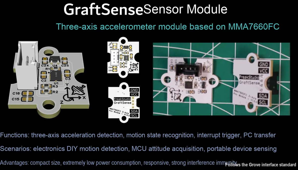
I. Module Introduction
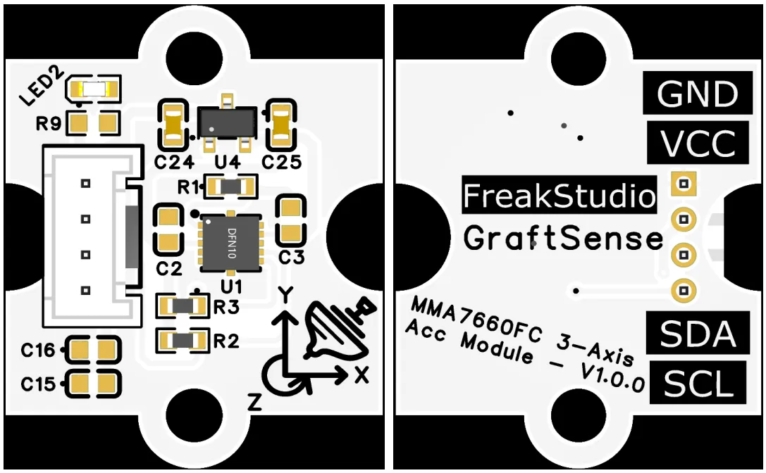
Tri-axis Acceleration Module Based on MMA7660FC, which adopts the MMA7660FCR1 digital Acceleration Sensor, communicates with I²C interface with MCU, and supports attitude detection, vibration monitoring and interrupt output; the module has a built-in 5V to 3.3V power supply circuit, adapts to 3.3V level MCU, and is equipped with I²C pull-up resistors and power supply decoupling capacitors, which can realize functions such as tilt detection and data ready, and is suitable for scenarios such as attitude perception, motion monitoring and embedded interaction.
II. Introduction to Major Chips
MMA7660FCR1 is a three-axis digital I²C interface Acceleration Sensor that supports posture detection, interrupt output and low-power operation, can realize functions such as vibration and tilt detection, and is suitable for consumer electronics and embedded posture perception scenarios.
2.1 Chip Overview
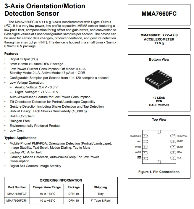
MMA7660FC is an ultra-light (±1.5g) three-axis capacitive MEMS Acceleration Sensor that features an I²C digital interface and comes in a 3mm×3mm×0.9mm DFN-10 package;It features low power consumption (0.4μA in shutdown mode, 2μA in standby mode, 47μA in operating mode), supports a configurable sampling rate ranging from 1 to 120 SPS, and has built-in tilt/gesture/vibration/tap detection as well as automatic wake-up/sleep functions. It can output interrupts via the INT pin, with an analog supply voltage of 2.4~3.6V and a digital supply voltage of 1.71~3.6V, and is resistant to 10000g impact. It is suitable for application scenarios such as mobile phone attitude detection, laptop anti-theft, and game motion sensing.
2.2 Pin Definition
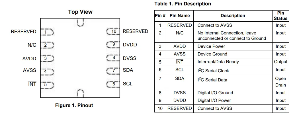
MMA7660FC adopts a 10-pin DFN package, and its pins are categorized as follows:
- Power Supply and Ground:
AVDD/AVSSare the analog power supply and ground,DVDD/DVSSare the digitalI/Opower supply and ground; - Communication and Interrupt:
SCL/SDAserve as theI²Cclock and data pins, andINTis the interrupt/data ready output pin; - Reserved and No-Connect Pins: Pins 1 and 10 shall be connected to
AVSS, pin 2 is a no-connect pin, and the rest are functional pins.
It clearly divides the functions of analog, digital and communication as a whole, which facilitates low-noise layout design.
2.3 Functional Block Diagram
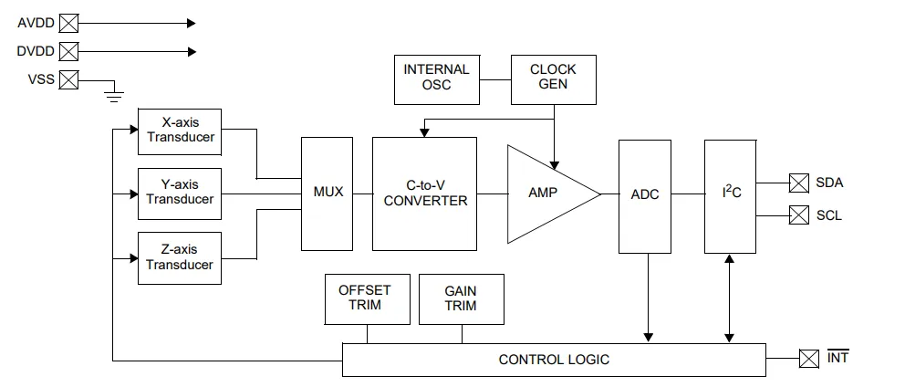
MMA7660FC has a functional block diagram centered on a three-axis capacitive MEMS transducer. After channel selection via a multiplexer (MUX), a capacitance-to-voltage converter (C-to-V CONVERTER) converts the micromechanical capacitance variation into a voltage signal, which is then digitized by an amplifier (AMP) and an ADC. The built-in clock generator and control logic handle offset/gain calibration, sampling control and interrupt management, and finally output acceleration data via the I²C interface; it also supports interrupt triggering via the INT pin to realize attitude and motion detection.
2.4 Performance Parameters
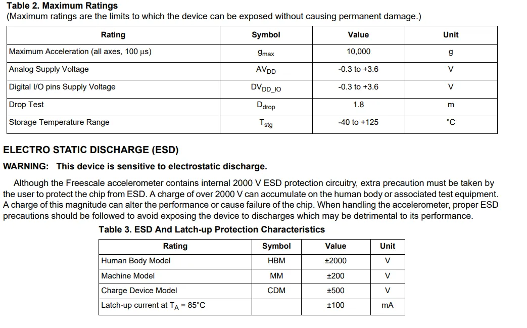
MMA7660FC has the following absolute maximum ratings: the maximum triaxial acceleration tolerance is 10000g (100μs), the analog and digital I/O power supply voltage range is -0.3V to + 3.6V, the drop test height is 1.8m, and the storage temperature range is -40℃ to + 125℃;ESD protection capability reaches HBM ±2000V, MM ±200V, CDM ±500V, and the latch-up current tolerance at 85℃ is ±100mA; exceeding these limits will cause permanent damage to the device.
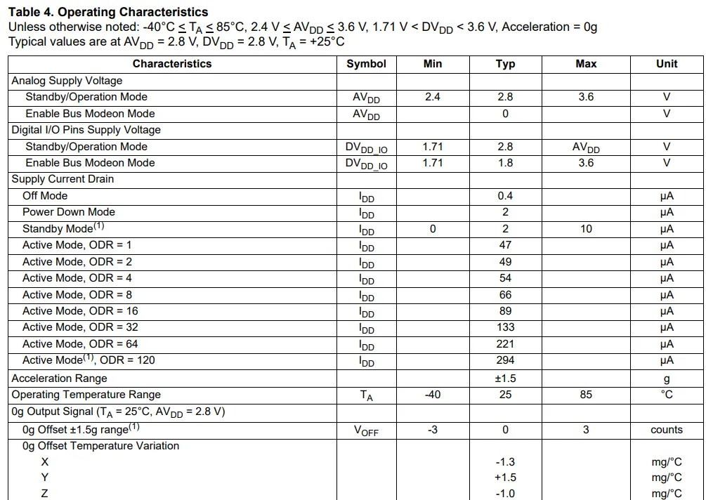
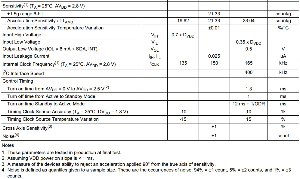
MMA7660FC has the following electrical characteristics:
- Power Supply and Power Consumption: Analog power supply 2.4~3.6V, digital
I/Opower supply 1.71~AVDD, only 0.4μA in shutdown mode, typical power consumption of 294μA in 120SPS active mode, featuring low power consumption advantage; - Measurement Performance: Acceleration range ±1.5g, typical sensitivity 21.33 count/g, 0g offset ±3 count, cross-axis sensitivity ±1%, noise ±1 count;
- Communication and Timing:
I²Cinterface with a maximum frequency of 400kHz, input high level ≥ 0.7×DVDD, input low level ≤ 0.35×DVDD, power-on startup time ≤ 1.3ms, transition time from standby to active mode is 12ms + 1/ODR; - Environmental Adaptability: Operating temperature: -40~85℃, internal clock: 135~165kHz, suitable for low-power attitude detection and motion perception scenarios.
2.5 Reference Circuit
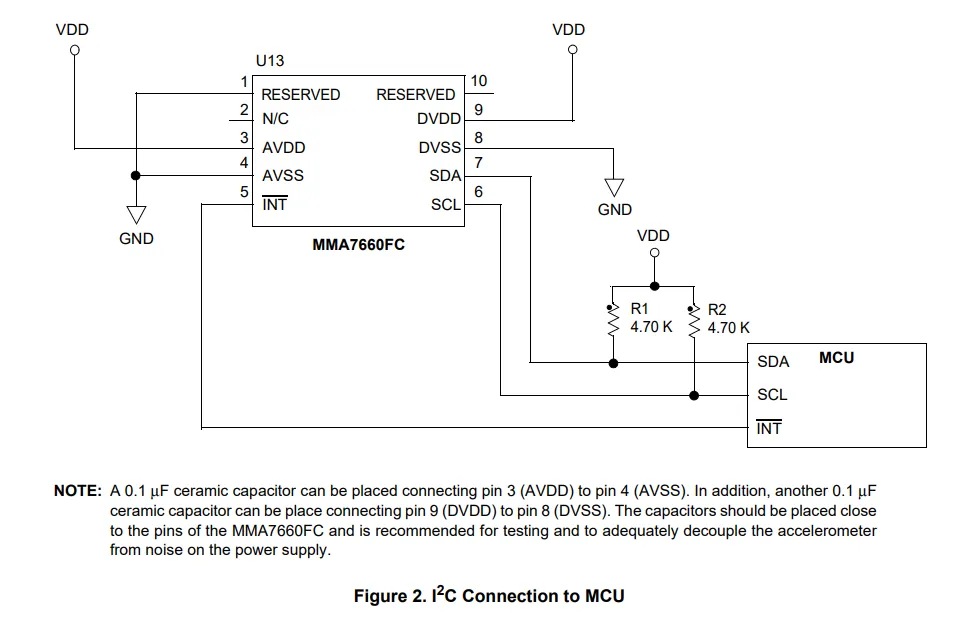
MMA7660FC and MCU in the I²C reference circuit, the analog power supply AVDD and digital power supply DVDD are both connected to VDD, AVSS and DVSS share a common ground. It is recommended to place a 0.1μF decoupling capacitor in the vicinity between AVDD - AVSS and DVDD - DVSS respectively to suppress noise;SDA, SCL pins are connected to VDD via 4.7kΩ pull-up resistors for communication with the MCU, the INT pin is directly connected to the MCU GPIO for interrupt notification, the reserved RESERVED pin is connected to AVSS, and the N/C pins are left floating or grounded, which can stably realize three-axis acceleration Data Acquisition and interaction.
2.6 Chip Configuration
None.
2.7 Communication Interfaces and Related Protocols
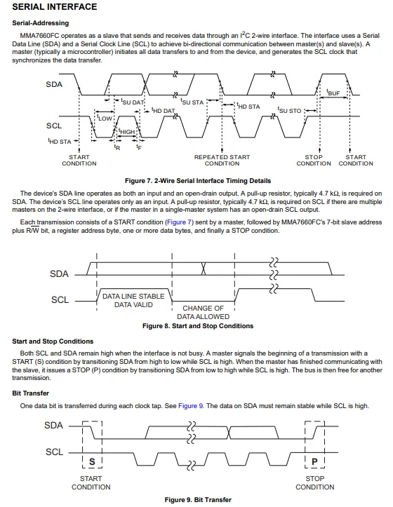
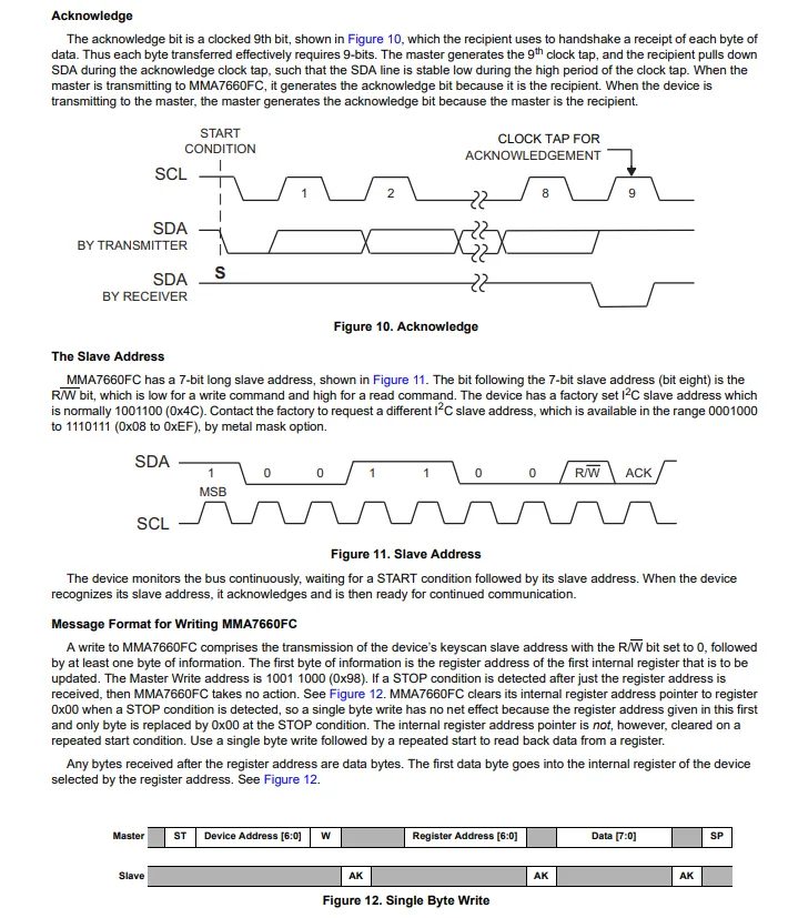
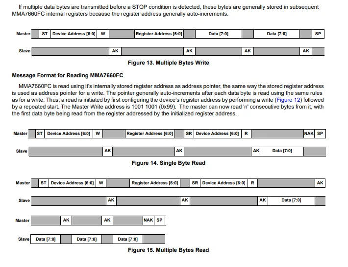
MMA7660FC adopts the I²C 2-wire serial interface for communication. SDA is an open-drain bidirectional data line requiring an external pull-up resistor, while SCL is driven by the host; communication starts with a host-initiated START condition and ends with a STOP condition, containing a 7-bit slave address (default 0x98, modifiable via metal mask) and a read/write bit, followed by an ACK / NACK response after each byte; both read and write operations start with specifying the register address, supporting single-byte and multi-byte continuous read/write (with automatic register address increment) to enable efficient interaction of acceleration data and configuration information.
2.8 PCB Routing Precautions
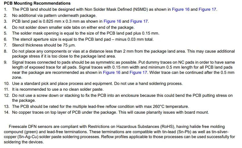
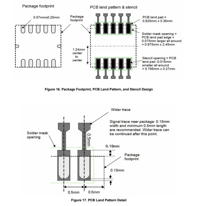
MMA7660FC PCB layout shall comply with the specific specifications for DFN packages:
- Pad design: adopts the
NSMDdefinition, with dimensions of 0.825mm×0.3mm; the solder mask opening is 0.15mm larger than the pad on each side, the stencil opening is 0.03mm smaller than the pad on each side, and the stencil thickness is 75μm; - Layout constraints: No traces/vias are allowed underneath the package, and no components/vias shall be placed within a 2mm perimeter to avoid package stress;
- Routing requirements: Signal traces shall be symmetrical, with a width of 0.15mm and a length ≥0.5mm near the package section,
NC padshall be added with dummy traces to keep consistent length; - Process and Stress: Lead-free reflow soldering (max. 260℃) is recommended; manual soldering is prohibited, and PCB bending caused by screw fastening or stacking shall be avoided.
PCBMeanwhile, the device complies withRoHSand halogen-free requirements.
III. Circuit Engineering
3.1 Circuit Source Engineering
To obtain the circuit source project, please follow the official account [Freak Embedded].
3.2 Module Usage Instructions
The schematic diagram of this module is shown below:
SCH_3-Axis Accelerometer Module Based on MMA7660FC-V1.0.0_2026-03-25.pdf 2.2 MB
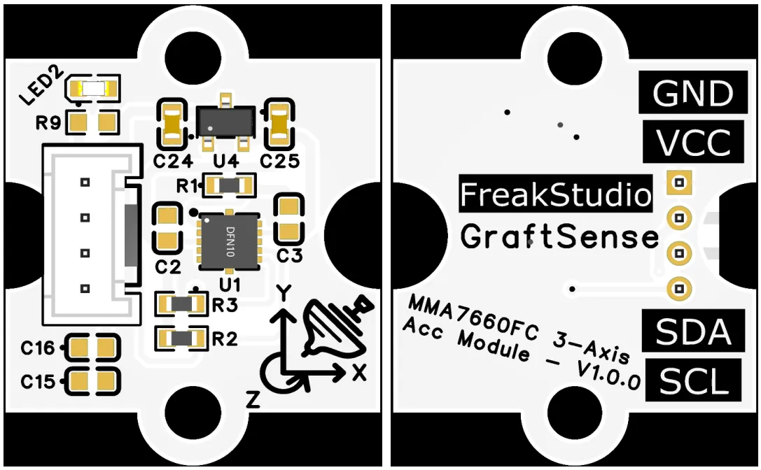
This module provides an I²C communication interface: it supports a standard I²C communication rate up to 400kHz, adopts a fixed 7-bit slave address (default 0x4C), the SDA / SCL pins are equipped with 4.7kΩ pull-up resistors and compatible with 3.3V level, which can stably realize the reading and writing of three-axis acceleration data and configuration registers as well as interrupt notification. It is applicable to scenarios such as attitude sensing, motion monitoring and embedded interaction, and provides the system with reliable low-power motion Data Acquisition and interaction capabilities.
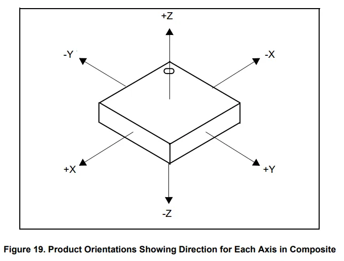
The azimuth diagram of the gyroscope is shown as follows:
3.3 Application Experiment
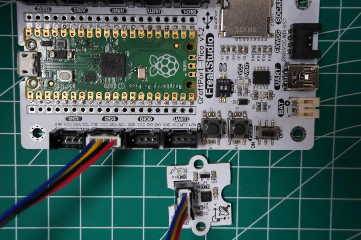
Here, we use the GraftPort-RP2040 development board for testing, and the MMA7660-based 3-axis acceleration module communicates with the main controller via the I2C interface.
Here, we first use the HY2.0-4P cable to connect the module to the GraftPort-RP2040 development board's I2C0 interface:
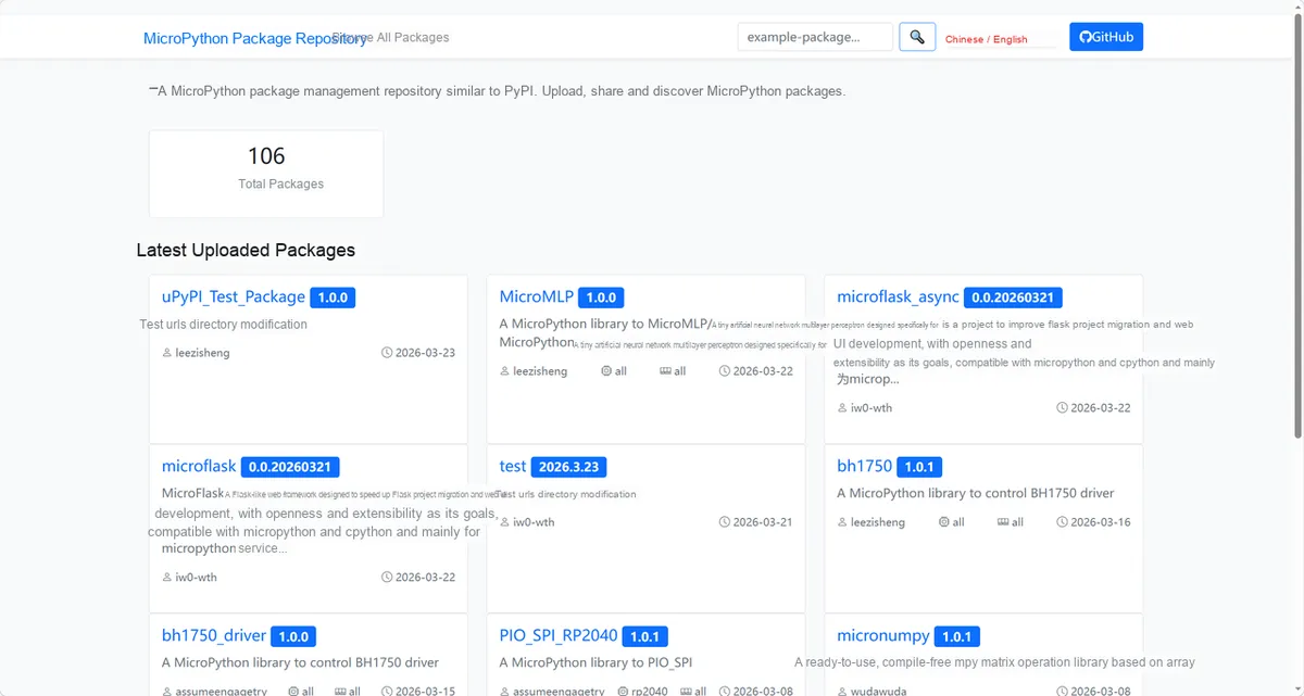
Here, we need to search for the relevant driver packages on uPyPI: https://upypi.net/zh/
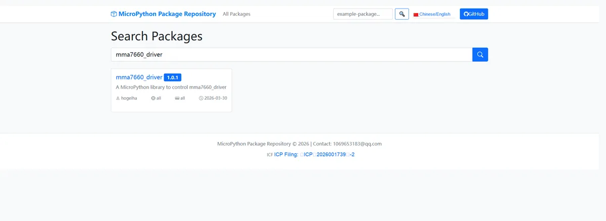
Enter mma7660_driver to search, and the following will be displayed:
Click to copy the local installation command:
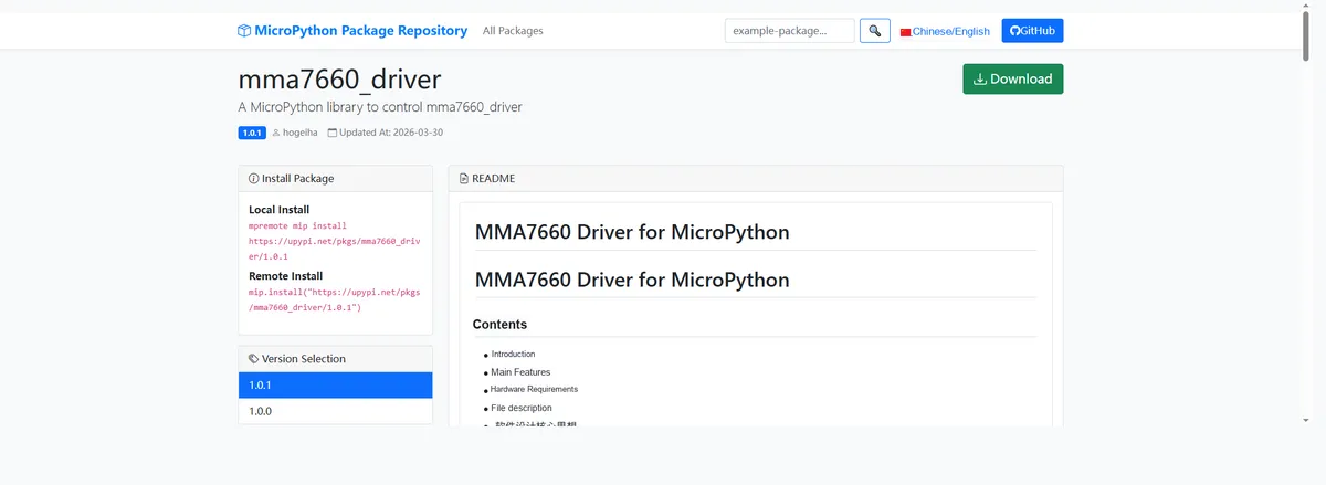
Import the module driver library code via the mip tool. Below are the usage commands for the mpremote tool:
mpremote mip install https://upypi.net/pkgs/mma7660_driver/1.0.0Import the MicroPython driver code for the MMA7660-based 3-axis acceleration module, then copy the following main.py code into our project:
# Python env   : MicroPython v1.23.0
# -*- coding: utf-8 -*-
# @Time    : 2026/3/20 5:30 PM
# @Author  : Developer
# @File    : main.py
# @Description : Data reading program for the MMA7660 three-axis accelerometer based on Raspberry Pi Pico, implementing I2C communication, device scanning, sensor initialization and continuous acceleration data reading

# ======================================== Import Modules =========================================

# Import the I2C and Pin modules for hardware I2C communication
from machine import I2C, Pin

# Import the sleep module for program delays
from time import sleep

# Import the MMA7660 accelerometer driver class
from mma7660 import Accelerometer

# ======================================== Global Variables ============================================

# Define the I2C SCL pin number (corresponds to GP5 of the Raspberry Pi Pico)
I2C_SCL_PIN = 5
# Define the I2C SDA pin number (corresponds to GP4 of the Raspberry Pi Pico)
I2C_SDA_PIN = 4
# Define the I2C communication frequency (400kHz is commonly used on the Pico)
I2C_FREQ = 400000
# Define the target I2C address of the MMA7660 accelerometer
TARGET_SENSOR_ADDR = 0x4C

# ======================================== Functions ============================================

# ======================================== Custom Classes ============================================

# ======================================== Initialization configuration ===========================================

# Delay 3 seconds after program starts to ensure hardware stability
sleep(3)
# Print program start message
print("FreakStudio: MMA7660 accelerometer data reading program started")

# Initialize I2C bus 0 and configure the SCL and SDA pins and the communication frequency
i2c_bus = I2C(0, scl=Pin(I2C_SCL_PIN), sda=Pin(I2C_SDA_PIN), freq=I2C_FREQ)

# Scan all devices on the I2C bus, return the list of device addresses, with type annotation added
devices_list: list[int] = i2c_bus.scan()
# Print I2C scan start message
print("START I2C SCANNER")

# Check the I2C scan result; exit the program if no device was found
if len(devices_list) == 0:
    print("No i2c device !")
    raise SystemExit("I2C scan found no devices, program exited")
else:
    # Print the number of I2C devices found
    print("i2c devices found:", len(devices_list))

# Initialize the sensor variable to None, to later receive the sensor instance
accel = None
# Iterate over the scanned I2C device address list to find the target sensor address
for device in devices_list:
    # Check whether the current device address is the target address of the MMA7660
    if device == TARGET_SENSOR_ADDR:
        # Print the hexadecimal address of the target sensor found
        print("I2c hexadecimal address:", hex(device))
        try:
            # Initialize the MMA7660 accelerometer
            accel = Accelerometer(i2c=i2c_bus)
            # Print the sensor initialization success message
            print("Target sensor initialization successful")
            # Exit the loop after the sensor is found and initialized successfully
            break
        except Exception as e:
            # Print the exception message for sensor initialization failure
            print(f"Sensor Initialization failed: {e}")
            # Continue to the next device address
            continue
else:
    # All addresses traversed without finding the target sensor; raise an exception
    raise Exception("No MMA7660 Accelerometer found on I2C bus")


# ========================================  Main Program  ============================================

# Read accelerometer data in an infinite loop
while True:
    # Read the X/Y/Z-axis acceleration values (unit: g)
    x_g, y_g, z_g = accel.getXYZ()
    # Read the X/Y/Z-axis acceleration values (unit: m/s²)
    x, y, z = accel.getAcceleration()

    # Print the acceleration values (unit: g), keeping two decimal places
    print(f"Acceleration(g): X={x_g:.2f}, Y={y_g:.2f}, Z={z_g:.2f}")
    # Print the acceleration values (unit: m/s²), keeping two decimal places
    print(f"Acceleration(m/s²): X={x:.2f}, Y={y:.2f}, Z={z:.2f}")
    # Print a separator line to improve output readability
    print("-" * 30)
    # Delay 0.5 s, then continue reading data
    sleep(0.5)
Burn the code, open the terminal, and the output is as follows:
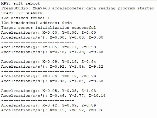
It can be seen that as we shake the module, the corresponding angle is output.
4. Drivers
mma7660_driver-1.0.1.zip 11 KB
5. BOM & Recommended Alternative Parts
None.
VI. Revision History
Document Version | Date of Revision | Modifier | Modify Content |
v1.0 | 2026-03-25 | Ling Gaoxing | Initialize the document |
v1.0.1 | 2026-04-05 | Li Zisheng | No photos for the homepage have been taken, the production files have not been exported yet, and all other items have been sorted out. |
v1.0.2 | 2026-04-21 | Li Zisheng | The production documents have not been exported yet, while all the rest have been sorted out. |
v1.1 | 2026-04-23 | Xin Ruili | Create an open version of the document, based on the internal document version v1.0.2. |
VII. Relevant Materials
7.1 Chip Datasheet
MMA7660FC.pdf 700 KB
7.2 PCB Silkscreen Specific Icons