Contents
- I. Module Introduction
- II. Introduction to Main Chips
- 2.1 Chip Overview
- 2.2 Pin Definition
- 2.3 Functional Block Diagram
- 2.4 Performance Parameters
- 2.5 Reference Circuit
- 2.6 Chip Configuration
- 2.7 Communication Interfaces and Related Protocols
- 2.8 PCB Routing Precautions
- III. Circuit Engineering
- 3.1 Circuit Source Engineering
- 3.2 Module Usage Instructions
- 3.3 Application Experiment
- IV. Drivers
- 5. BOM & Recommended Alternative Parts
- VI. Revision History
- VII. Relevant Materials
- 7.1 Chip Datasheet
- 7.2 Unique Icons for PCB Silk Screen
I. Module Introduction
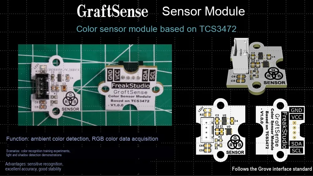
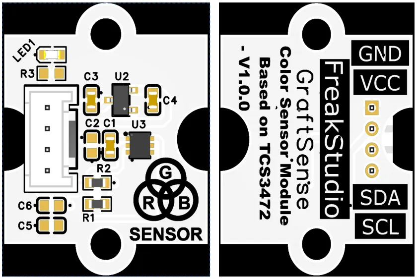
Color sensor module based on TCS3472, which adopts the TCS3472 chip solution with a built-in infrared cut-off filter, can output the digital sensing values of red, green, blue and clear light (RGBC) through the I2C interface, making color measurement closer to human vision; the module supports adjustable integration time and gain, features a high dynamic range to maintain high sensitivity under different light intensities, and also supports a programmable low-power mode. Powered by 3.3V and equipped with LDO voltage regulator, power filtering and indicator light circuits, it is suitable for scenarios such as color detection, light source identification, and ambient light monitoring.
II. Introduction to Main Chips
TCS3472 is a digital I2C interface color ambient light sensor with an infrared cut-off filter, RGB that can accurately detect color and ambient light intensity, featuring low power consumption and being suitable for embedded color sensing applications.
2.1 Chip Overview
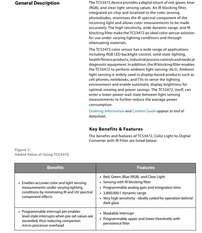
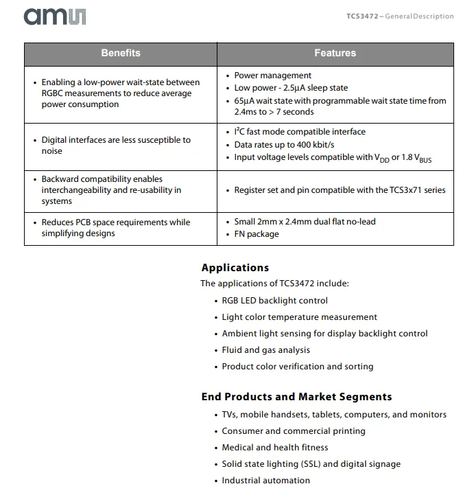
TCS3472 is a digital RGB / ambient light sensor with an infrared cut-off filter. It supports programmable gain and integration time, offers a dynamic range of up to 3,800,000:1, and enables accurate color and light intensity measurement under various lighting conditions.Adopts the I²C interface (max. 400kbps), features low power consumption with a sleep current of 2.5μA and a standby current of 65μA, comes with programmable threshold interrupt, and is packaged in a compact FN package measuring 2mm×2.4mm. It is widely used in scenarios such as display backlight control, color temperature measurement, product color sorting, medical equipment, and industrial automation.
2.2 Pin Definition
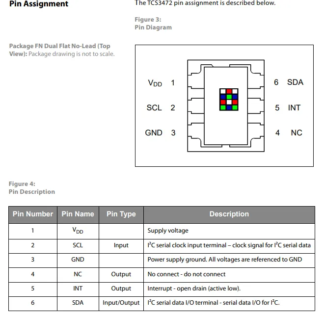
TCS3472 (FN package) pin definitions: Pin 1 VDD is power supply pin, Pin 2 SCL serves as I²C clock input, Pin 3 GND is power ground, Pin 4 NC is no connection, Pin 5 INT is open-drain active-low interrupt output, Pin 6 SDA serves as I²C serial data input/output.
2.3 Functional Block Diagram
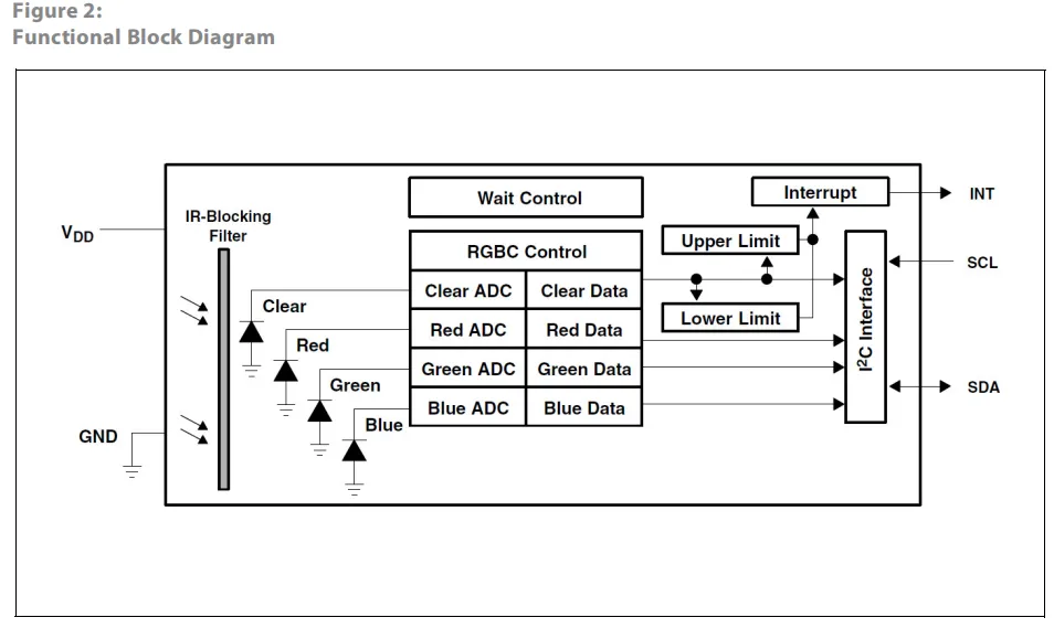
The TCS3472 sensor filters out infrared light through an infrared cut-off filter, after which the red, green, blue and clear channel photodiodes collect optical signals respectively, which are converted into digital data via their respective ADC s, then processed by the RGBC Control Unit, and cooperate with the wait control module to achieve low-power management; the data can communicate with the main controller through the I²C interface, and meanwhile trigger an interrupt signal via the upper and lower limit comparison module to realize accurate detection and feedback of ambient light and color.
2.4 Performance Parameters
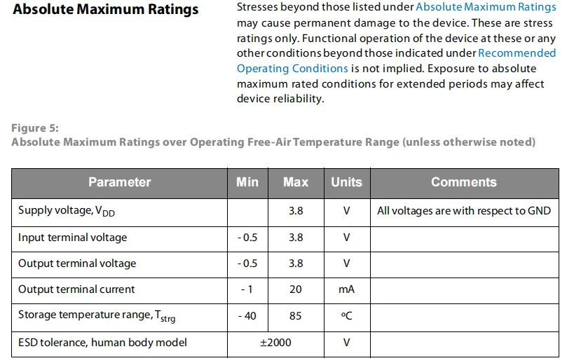
TCS3472 's absolute maximum ratings table specifies the extreme operating conditions of the device: the supply voltage VDD has a maximum value of 3.8V, the voltage range of input/output pins is -0.5V to 3.8V, the current range of output pins is -1mA to 20mA, the storage temperature range is -40°C to 85°C, and the human body model ESD tolerance is ±2000V; exceeding these conditions may cause permanent damage to the device.
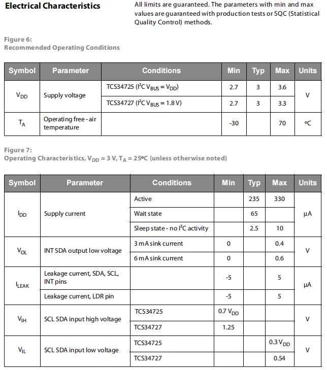
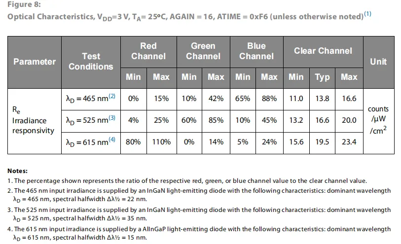
TCS3472 key electrical and optical parameters: the recommended supply voltage is 2.7-3.3V (for TCS34727), and the operating temperature ranges from -30°C to 70°C; when powered at 3V, it features a typical operating current of 235μA, a standby current of 65μA, and a sleep current as low as 2.5μA, with specifications also defined for I/O levels, leakage current and other indicators; for the optical section, the irradiance responsivity of the red, green, blue and full channels at wavelengths of 465nm, 525nm and 615nm is provided, in the unit of counts/μW/cm², clearly defining the sensitivity range of each channel.
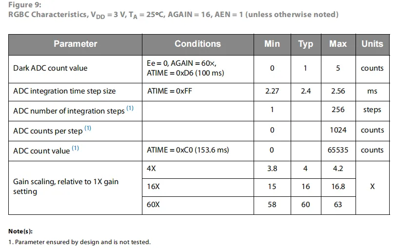
TCS3472 under the conditions of 3V power supply, 25°C and 16x gain, the RGBC photoelectric conversion characteristics include: typical dark current count of 1, maximum 5 counts;ADC integration time step is typically 2.4ms, supports up to 256 integration steps, maximum 1024 counts per step, and the full scale can reach 65535 counts; it also defines the actual scaling factors for 4/16/60x gains to meet the measurement requirements of different light intensities.
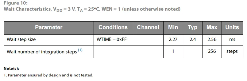
The TCS3472 sensor features standby characteristics under 3V supply and 25°C ambient conditions: the typical wait time step is 2.4ms (ranging from 2.27ms to 2.56ms), and it supports 1 to 256 configurable wait integration steps. Users can adjust the low-power wait duration by configuring the WTIME register to optimize the average power consumption of the sensor.
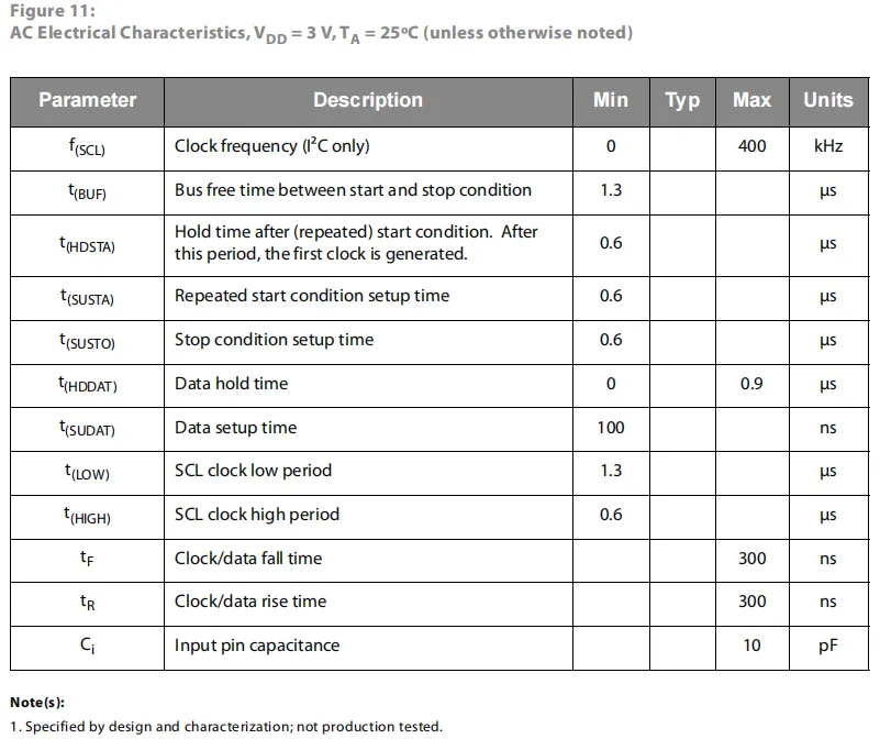
TCS3472 defines the AC electrical characteristics of the I²C interface under a 3V power supply and 25°C, supporting a maximum clock frequency of 400kHz. It also specifies key timing parameters including bus idle time, setup and hold times for start / repeated start / stop conditions, data setup / hold times, clock high and low pulse widths, signal rise / fall times, and pin input capacitance (max 10pF).
2.5 Reference Circuit
None.
2.6 Chip Configuration
None.
2.7 Communication Interfaces and Related Protocols
2.7.1 I2C Communication
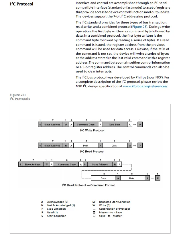
TCS3472 I²C Communication Protocol adopts standard/fast mode I²C interface with 7-bit addressing, and supports three bus transactions: write, read, and combined read-write. For a write operation, the slave address (with write bit) and command code are sent first, followed by data; for a read operation, data can be read directly by sending the slave address (with read bit); for a combined read-write operation, the command code is written first, then a repeated start condition and read address are sent to achieve continuous data reading after the register address is specified. During communication, the slave confirms reception with an ACK signal.
2.7.2 Registers
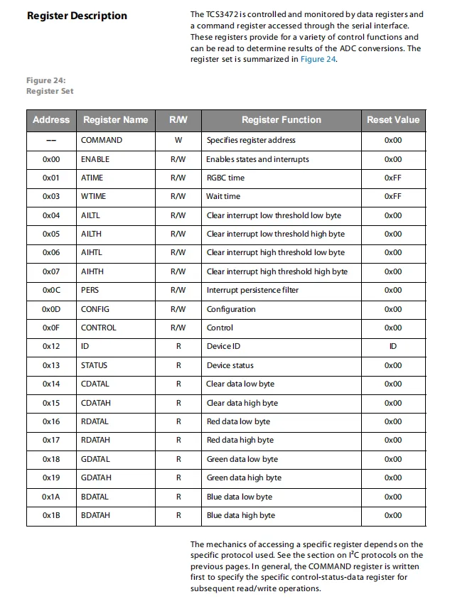
TCS3472 register list: addresses of each functional register can be specified via the I²C interface through the COMMAND register for read and write operations. These registers include: enable/control registers (ENABLE, ATIME, WTIME, CONTROL), interrupt configuration registers (AILTL / AILTH / AIHTL / AIHTH, PERS), status indicator registers (ID, STATUS), and RGBC data registers (CDATAL/H, RDATAL/H, GDATAL/H, BDATAL/H), which enable working mode configuration of the sensor and reading of ADC conversion results.
2.7.2.1 Command Register
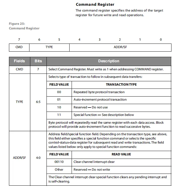
Command Register Format: The most significant bit CMD bit must be written as 1;TYPE bits (bits 6-5) are used to specify the subsequent data transfer type, including repeated byte protocol, auto-increment protocol and special functions; the lower 4 bits of the ADDR / SF field are used to select the target register address or execute a special function. For example, 00110 can perform the special operation of clearing the channel interrupt, so as to realize the control over the sensor register access mode and interrupt status.
2.7.2.2 ENABLE Register (Address 0x00)
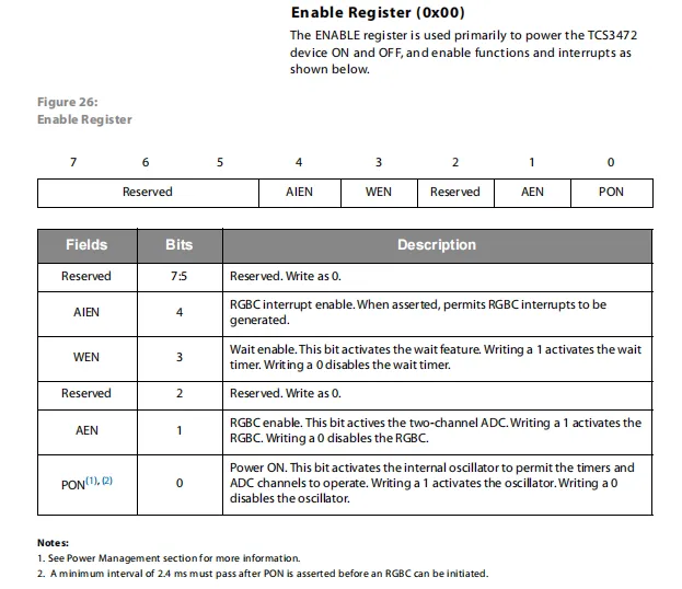
ENABLE Register (address 0x00) is used to control the power supply and function switches of the sensor: Bit 0 (PON) controls the power supply of the internal oscillator, Bit 1 (AEN) enables the RGBC ADC, Bit 3 (WEN) activates the low-power wait timer, Bit 4 (AIEN) turns on the RGBC interrupt; all other reserved bits must be written as 0. The combination of these bits enables the control of the sensor's power-on, measurement, low-power, and interrupt functions.
2.7.2.3 RGBC Timing Register (0x01) & Wait Time Register (0x03)
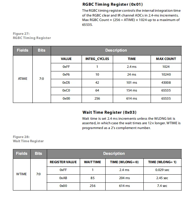
RGBC Timing Register (0x01) field, with a step size of 2.4ms; 1 to 256 integration cycles are configurable, corresponding to a measurement duration of 2.4 to 614ms, which directly affects the maximum count value (ranging from 1024 to 65535). ADC integration time via the ATIME field, with a step size of 2.4ms; 1 to 256 integration cycles are configurable, corresponding to a measurement duration of 2.4 to 614ms, which directly affects the maximum count value (ranging from 1024 to 65535).
The waiting time register (0x03) sets the low-power waiting duration between two measurements via the WTIME field. The default step size is 2.4ms; when the WLONG bit is enabled, the step size is amplified by 12 times, supporting a maximum waiting period of 7.4 seconds, thus enabling flexible adjustment of sensor power consumption and refresh rate.
2.7.2.4 Interrupt Threshold Registers (0x04 - 0x07) & Duration Register (0x0C)
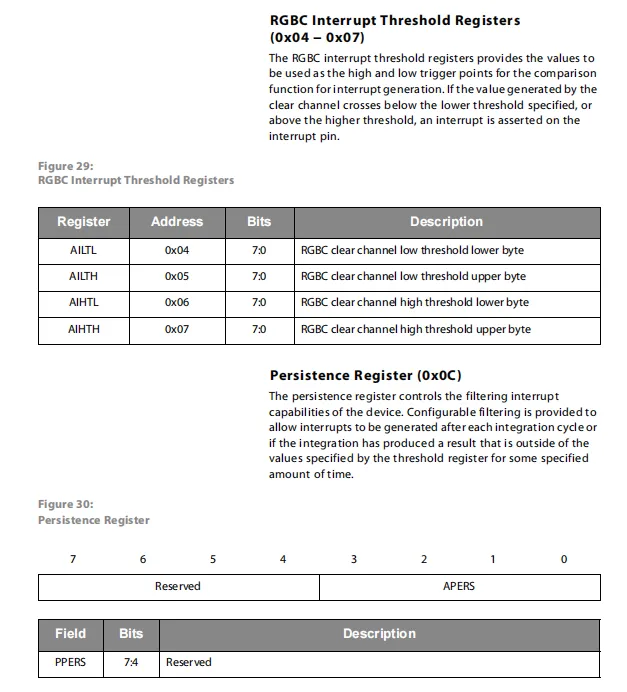
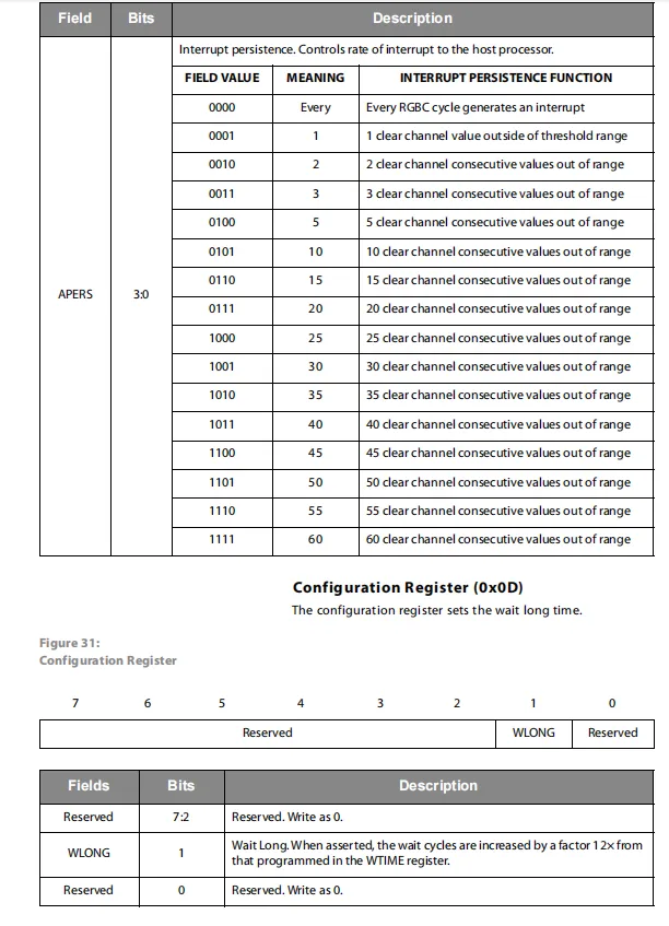
Interrupt threshold register (0x04 - 0x07) sets the upper and lower interrupt limits for the clear channel via high and low bytes, and triggers an interrupt when the measured value exceeds the range.
The persistence register (0x0C)'s APERS field can configure the interrupt trigger condition, supporting triggering from every cycle to triggering only after 60 consecutive overlimits, which effectively filters noise; the 0x0D configuration register' s WLONG bit can amplify the waiting time set by WTIME by 12 times, achieving a low-power interval of up to 7.4 seconds and optimizing power consumption and refresh rate.
2.7.2.5 Control Register (0x0F)
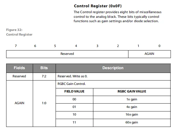
Control register (0x0F): the lower 2 bits of its AGAIN field are used to set the analog gain of the RGBC channel, supporting four selectable levels: 1x, 4x, 16x and 60x; the remaining higher bits are reserved bits that must be written as 0. By adjusting the gain, it can adapt to lighting environments of different brightness and improve the measurement sensitivity in low-light scenarios.
2.7.2.6 ID Register (0x12) & Status Register (0x13)
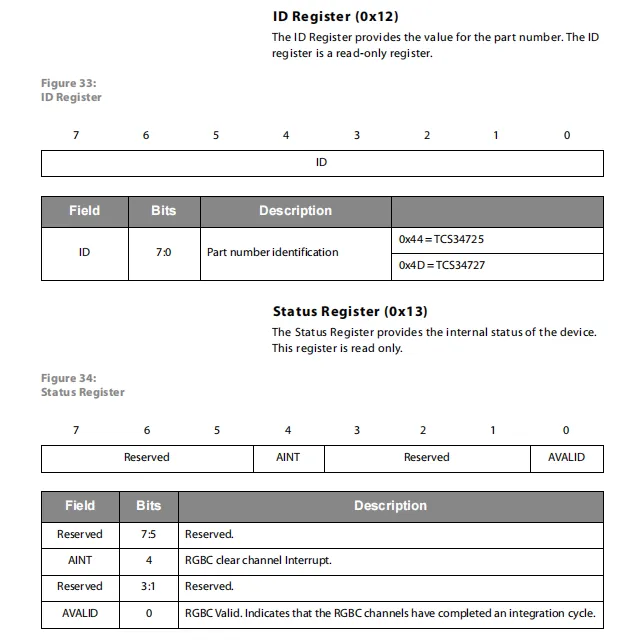
ID Register (0x12) stores the device model identifier. The corresponding value for TCS34725 is 0x44, and that for TCS34727 is 0x4D, which is used to identify the chip version.
The status register (0x13) provides feedback on the operating status: bit 0's AVALID indicates that the RGBC channel has completed an integration cycle, and bit 4's AINT indicates whether the clear channel interrupt is triggered, facilitating the host to read the sensor's operating status and events.
2.7.2.7 RGBC Channel Data Registers (0x14 – 0x1B)
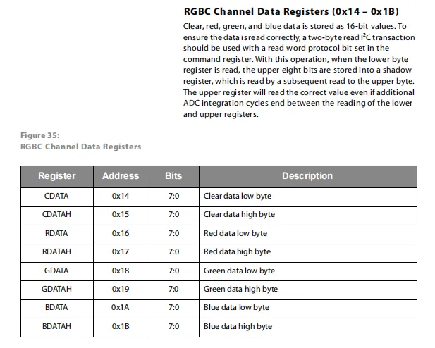
RGBC Channel Data Registers (0x14 – 0x1B): Clear, Red, Green, and Blue four-channel ADC conversion results are stored in 16-bit format, with each channel split into two registers: a low byte and a high byte. It is recommended to use the I²C word read protocol for reading operations. When reading the low byte first, the high byte will be stored in the shadow register; even if a new integration cycle completes between the two reads, this ensures that a consistent set of data is retrieved, preventing errors caused by value fluctuations.
2.8 PCB Routing Precautions
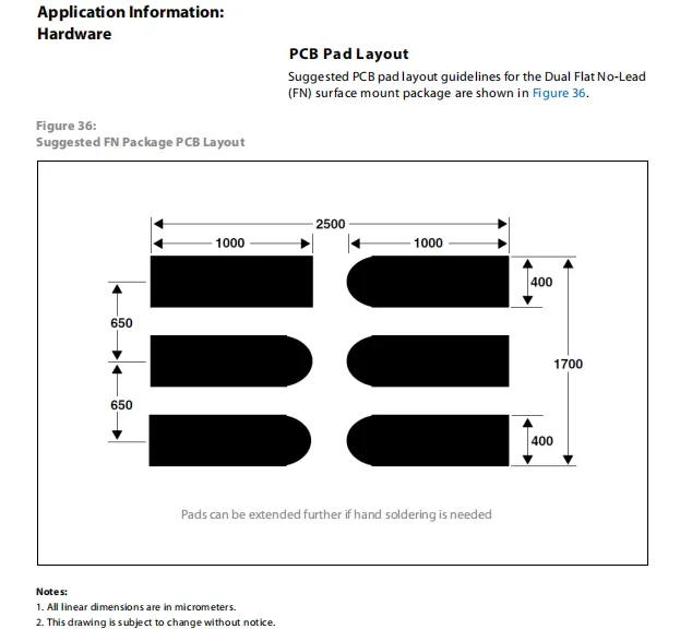
TCS3472 sensor FN package recommended PCB pad layout dimensions, in micrometers, with 3 pads in each of the left and right rows; the pad spacing, width and length are clearly specified, and it is noted that the pads can be further extended according to manual soldering requirements to facilitate users' PCB design and patch soldering.
III. Circuit Engineering
3.1 Circuit Source Engineering
To obtain the circuit source project, please follow the official account [Freak Embedded]
3.2 Module Usage Instructions
The schematic diagram of this module is shown below:
SCH_Schematic1_TCS3472-Based Color Sensor Module_v1.0.0_2026-05-07.pdf 2.1 MB
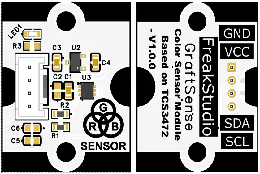
This module provides an IIC communication interface: it supports standard I2C communication rates, is compatible with 3.3V logic levels, and can stably transmit the red, green, blue and clear light (RGBC) digital sensing values collected by the TCS3472. It is suitable for scenarios such as color detection, light source identification, and ambient light monitoring, providing the system with reliable color perception data interaction capability.
3.3 Application Experiment
Here, we use the GraftPort-RP2040 development board for testing, and the TCS3472-based color sensor module uses the I2C interface to communicate with the main controller.
Here, we first use the HY2.0-4P cable to connect the module to the GraftPort-RP2040 development board's I2C0 interface:
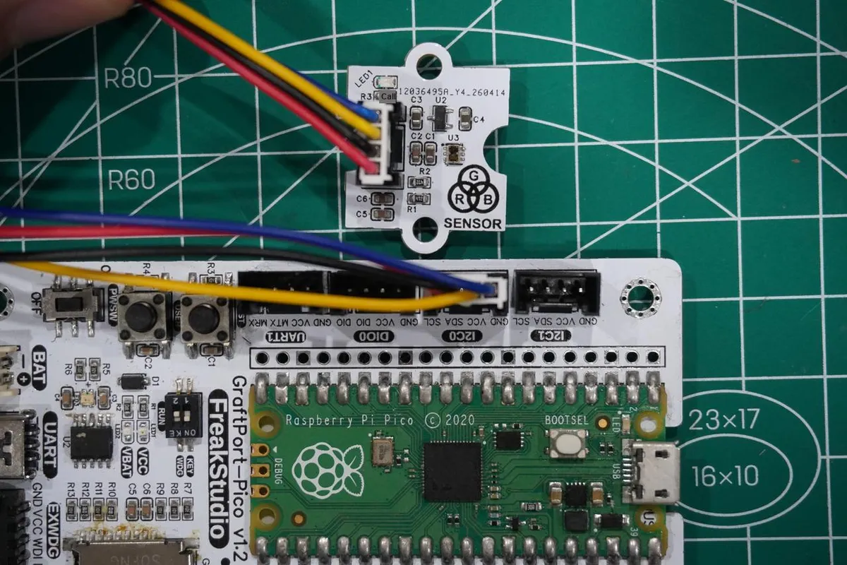
development board pins | Module Pins | Description |
Pin 4 |
|
|
Pin 5 |
|
|
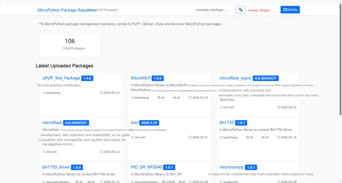
Here, we need to search for the relevant driver packages on uPyPI: https://upypi.net/zh/
Enter tcs3472_driver to search, and the following will be displayed:
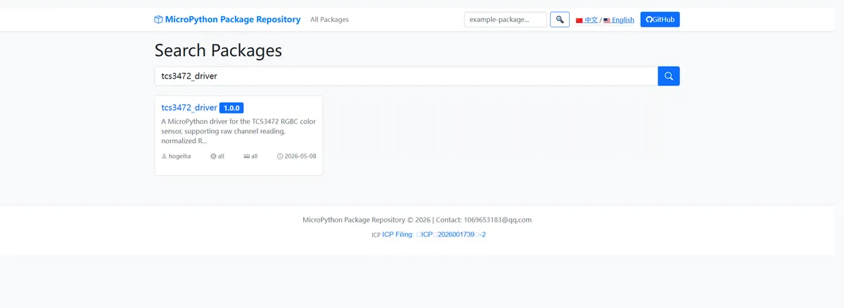
Click to copy the local installation command:
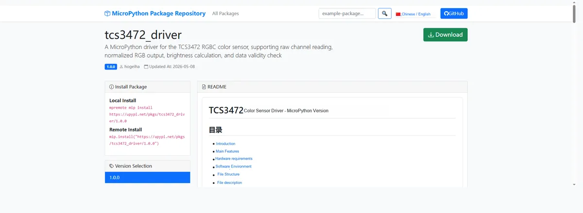
Import the module driver library code via the mip tool. Below are the usage commands for the mpremote tool:
mpremote mip install https://upypi.net/pkgs/tcs3472_driver/1.0.0Import the MicroPython driver code for the TCS3472-based color sensor module, then copy the following main.py code into our project:
# Python env   : MicroPython v1.23.0
# -*- coding: utf-8 -*-
# @Time    : 2026/4/21 6:30 PM
# @Author  : hogeiha
# @File    : main.py
# @Description : TCS3472 color sensor driver and test

# ======================================== Import Modules =========================================

from machine import Pin, SoftI2C
import tcs3472
import time

# ======================================== Global Variables ============================================

# Automatically identify the sensor address, define a global target address list (supports multiple addresses; use [] even for a single one)
TARGET_SENSOR_ADDRS = [0x29]

# I2C pin and frequency configuration
I2C_SDA_PIN = 4
I2C_SCL_PIN = 5
I2C_FREQ = 400000


# ======================================== Functions ============================================

def recognize_color(r, g, b):
    # Detect black (very low brightness)
    if r < 30 and g < 30 and b < 30:
        return "Black"
    # Detect white (RGB all high and balanced)
    elif r > 110 and g > 110 and b > 110:
        return "White"
    # Detect red: R is largest and R>110
    elif r > 110 and r > g and r > b:
        return "Red"
    # Detect green: G is largest and G>110
    elif g > 110 and g > r and g > b:
        return "Green"
    # Detect blue: B is largest and B>110
    elif b > 110 and b > r and b > g:
        return "Blue"
    # Detect yellow: both R and G are high
    elif r > 110 and g > 110 and b < 90:
        return "Yellow"
    # Other colors
    else:
        return "Unknown"

# ======================================== Custom Classes ============================================

# ======================================== Initialization configuration ===========================================

time.sleep(3)
print("FreakStudio: TCS3472 color sensor test")


# ========================================  Main Program  ============================================

# I2C initialization (compatible with I2C/SoftI2C)
i2c_bus = SoftI2C(sda=Pin(I2C_SDA_PIN), scl=Pin(I2C_SCL_PIN), freq=I2C_FREQ)

# Start scanning for devices on the I2C bus
devices_list: list[int] = i2c_bus.scan()
print("START I2C SCANNER")

# Check the I2C device scan result
if len(devices_list) == 0:
    print("No i2c device !")
    raise SystemExit("I2C scan found no devices, program exited")
else:
    print("i2c devices found:", len(devices_list))

# Iterate over the address list to initialize the target sensor
sensor = None  # Placeholder for the sensor object initialization
for device in devices_list:
    if device in TARGET_SENSOR_ADDRS:
        print("I2c hexadecimal address:", hex(device))
        try:
            # Automatically identify and initialize the corresponding sensor
            sensor = tcs3472.tcs3472(i2c_bus, device)
            print("Sensor initialization successful")
            break
        except Exception as e:
            print(f"Sensor Initialization failed: {e}")
            continue
else:
    # Target device not found, raise an exception
    raise Exception("No target sensor device found in I2C bus")

# Main loop
print("TCS3472 color sensor initialized successfully!")
while True:
    # Check whether the sensor data is valid
    if sensor.valid():
        # Get ambient light brightness
        light_val = sensor.light()
        # Get RGB values (0-255)
        r, g, b = sensor.rgb()
        # Identify color name
        color_name = recognize_color(r, g, b)

        # Print the result
        print(f"Light: {light_val:>4} | RGB: ({r:3}, {g:3}, {b:3}) | Color: {color_name}")
    else:
        print("Sensor data invalid!")

    # Delay 500ms to avoid refreshing the screen too fast
    time.sleep(0.5)
Burn the code, open the terminal, and the output is as follows:
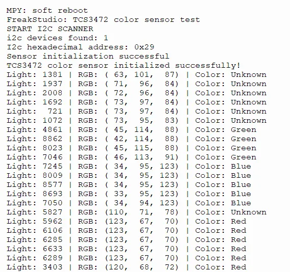
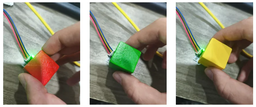
We can see that the TCS3472 color sensor features normal I2C communication and initialization, stably outputs light intensity and RGB channel data, and can recognize colors such as green, blue and red, though it may be judged as Unknown in some scenarios affected by light conditions, with normal working response.
IV. Drivers
tcs3472_driver-1.0.0.zip 10 KB
5. BOM & Recommended Alternative Parts
None.
VI. Revision History
Document Version | Date of Revision | Modifier | Modify Content |
v1.0 | 2026-05-07 | Zero High-Luck | Initialize the document |
v1.1 | 2026-06-06 | Xin Ruili | Create an open version of the document based on the internal document version v1.0. |
VII. Relevant Materials
7.1 Chip Datasheet
TCS34727FN.pdf 1.5 MB
7.2 Unique Icons for PCB Silk Screen