Contents
- I. Module Introduction
- II. Introduction to Main Chips
- 2.1 Chip Overview
- 2.2 Pin Definition
- 2.3 Functional Block Diagram
- 2.4 Performance Parameters
- 2.5 Reference Circuit
- 2.6 Chip Configuration
- 2.7 Communication Interfaces and Related Protocols
- 2.8 PCB Routing Precautions
- III. Circuit Engineering
- 3.1 Circuit Source Engineering
- 3.2 Module Usage Instructions
- 3.3 Application Experiment
- IV. Drivers
- 5. BOM & Recommended Alternative Parts
- VI. Revision History
- 7. Relevant Materials
- 7.1 Chip Datasheet
- 7.2 Unique Icons for PCB Silk Screen
I. Module Introduction
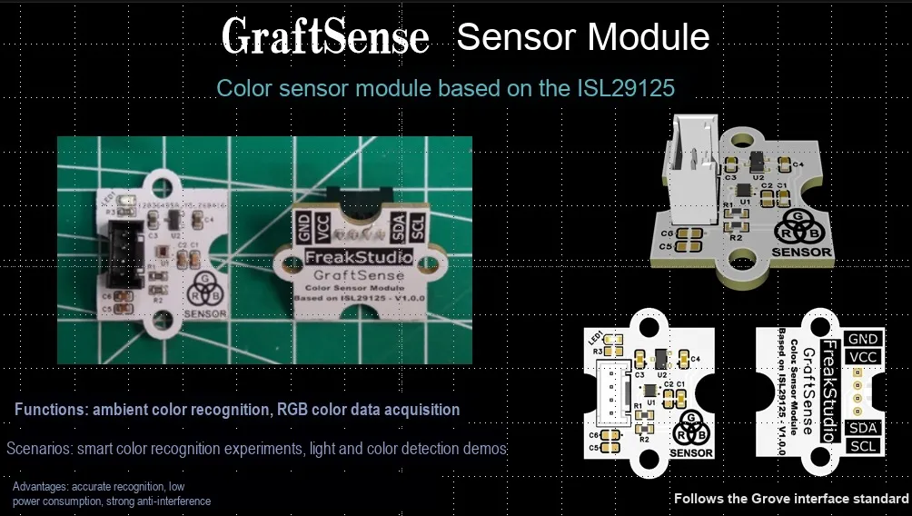
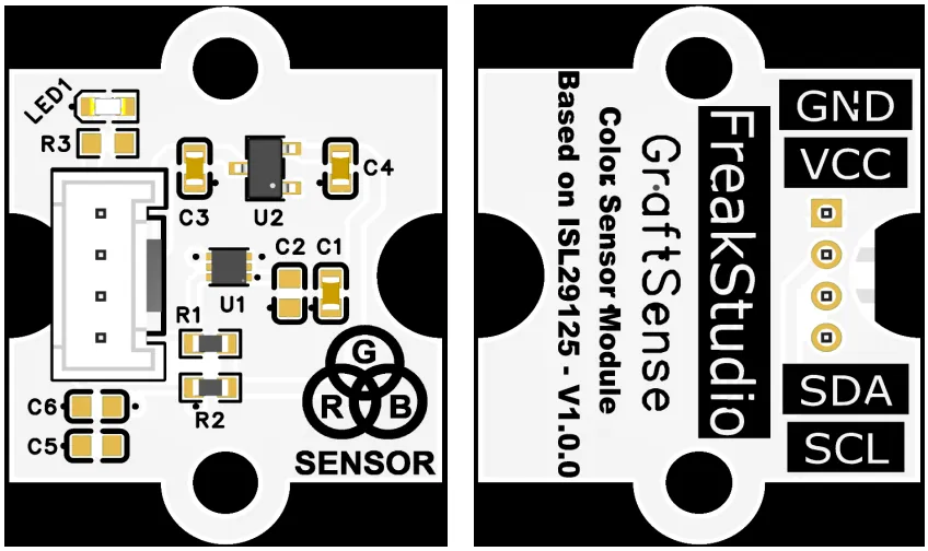
ISL29125-based color sensor module that adopts the ISL29125IROZ chip solution, integrates three independent 16-bit ADC and a physical-level IR cut-off filter. It can simulate human visual perception, convert the intensity of red, green and blue light into 16-bit digital signals for output, effectively eliminate infrared interference, and realize high-precision color recognition;The module is equipped with LDO voltage regulator circuits, power filtering and indicator light circuits, powered by 3.3V and supporting I2C communication. It features a typical operating current of only 56μA with outstanding low-power characteristics, making it suitable for scenarios such as color detection, light source identification, and ambient light monitoring.
II. Introduction to Main Chips
ISL29125 is Renesas 's newly launched low-power, high-sensitivity RGB color light sensor with I²C interface and infrared suppression function; it has a built-in 16-bit ADC and can accurately measure the color and intensity of ambient light.
2.1 Chip Overview
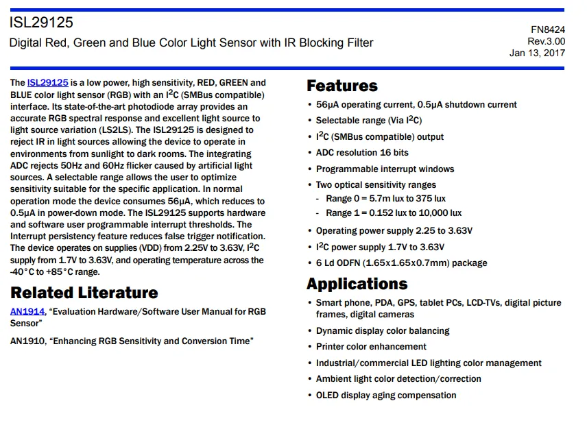
ISL29125 is a digital RGB color light sensor with infrared filtering function, which communicates via I²C (compatible with SMBus) interface and features a 16-bit ADC resolution.It features ultra-low power consumption, with an operating current of only 56μA and a shutdown current as low as 0.5μA. It supports two selectable measurement ranges: 5.7m~375lux and 0.152~10000lux, operates on a supply voltage of 2.25~3.63V, and comes in a 6-pin package measuring 1.65×1.65×0.7mm. It can filter out infrared interference and 50/60Hz light flicker, and is widely used in scenarios such as smartphones, display color calibration, LED lighting management, etc.
2.2 Pin Definition
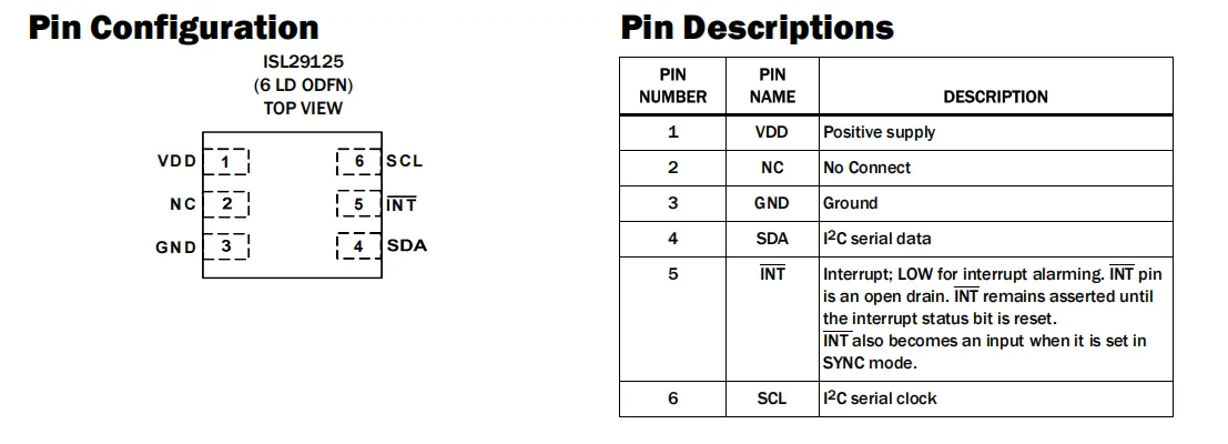
ISL29125 (6-pin ODFN package) pin configuration and definition: Pin 1 is VDD power supply, Pin 2 is no connection NC, Pin 3 is GND ground, Pin 4 is I²C data SDA, Pin 5 is open-drain interrupt output INT (active low, supports Synchronization Mode), Pin 6 is I²C clock SCL.
2.3 Functional Block Diagram
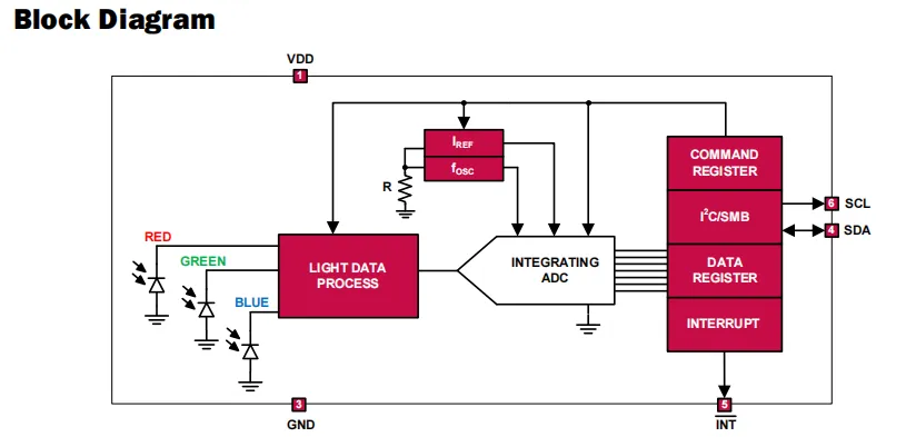
The ISL29125 collects optical signals of different wavelength bands via its built-in red, green and blue photodiodes; after the optical data processing unit filters out infrared interference, the signals are sent to an integrating ADC with a current reference and an oscillator to be converted into digital values, which are then temporarily stored in the data register, and finally output to the main controller via the I²C / SMBus interface. Meanwhile, it can send signals to the main controller through the interrupt module, realizing accurate detection and feedback of ambient light colors.
2.4 Performance Parameters
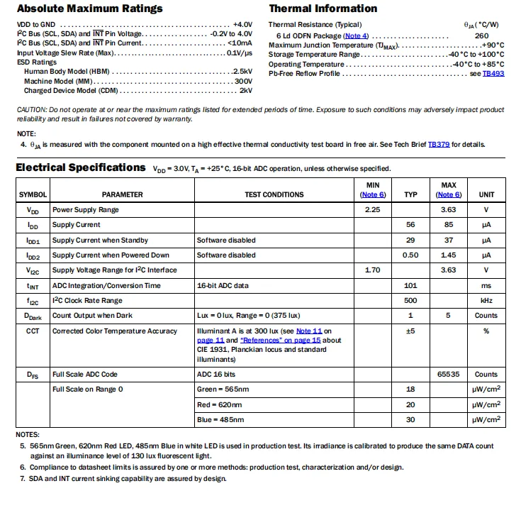
ISL29125 features a supply voltage range of 2.25V to 3.63V, I²C interface supply voltage of 1.70V to 3.63V, a typical operating current of 56μA, a shutdown current as low as 0.5μA, a typical integration time of 101ms for the 16-bit ADC, a maximum I²C clock of 500kHz, and also provides full-scale light intensity parameters under different wavelength light sources as well as reliability indicators such as temperature and ESD.
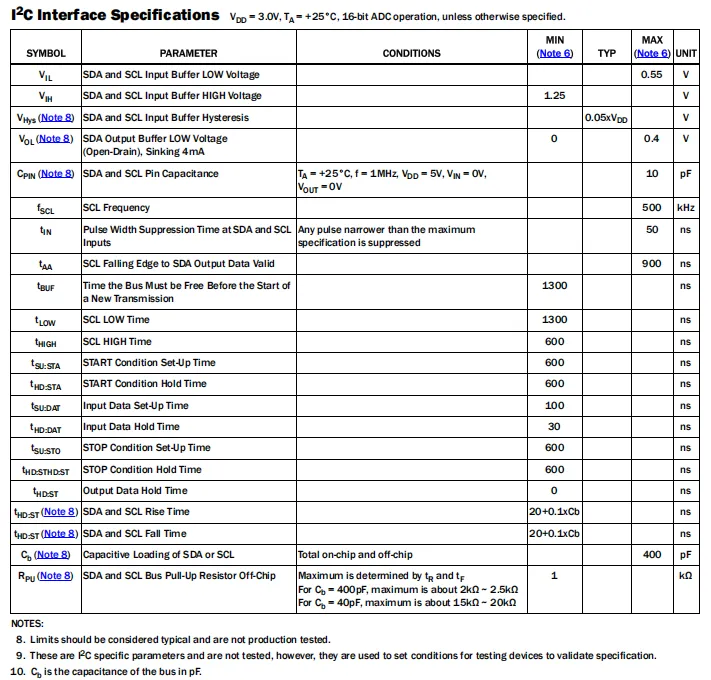
ISL29125 's I²C interface electrical specifications define the timing parameters such as the high and low level thresholds of the SDA / SCL pins, maximum 500kHz clock frequency, rise/fall time, setup/hold time, and bus idle time; they also stipulate pin capacitance, open-drain output low level, pull-up resistance range, etc. , and clarify the interface electrical and timing requirements under standard test conditions.
2.5 Reference Circuit
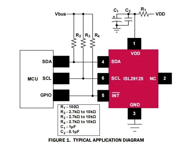
The sensor receives stable power supply via its power input terminal VDD connected to a 100Ω current-limiting resistor R1 and filter capacitors C1 (1μF) and C2 (0.1μF), with GND grounded; the SDA and SCL pins are connected to the MCU via 2.7kΩ~10kΩ pull-up resistors R2 and R3 to implement I²C communication; the INT pin is pulled up via R4 and connected to the GPIO of the MCU for interrupt signal output, while the NC pin is left floating, forming a complete application solution for an RGB light sensor as a whole.
2.6 Chip Configuration
None.
2.7 Communication Interfaces and Related Protocols
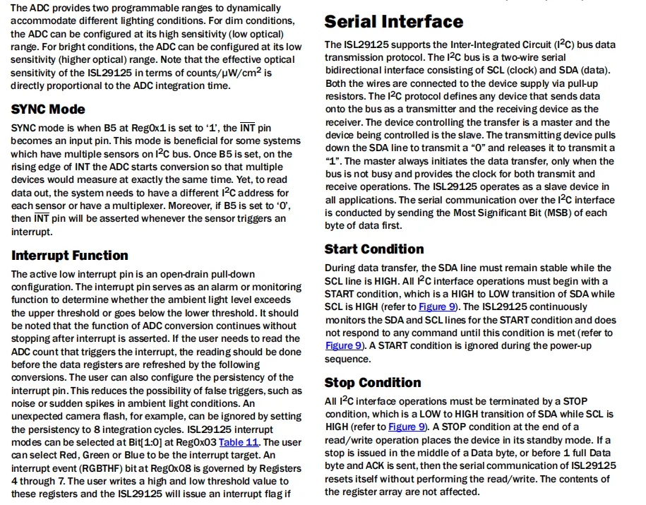
ISL29125 's I ² C serial interface: using two-wire bidirectional communication ( SCL clock, SDA data), the device always acts as a slave in the bus, and the communication is transmitted preferentially at a high level ( MSB ), initiated by the host and provides a clock for data transmission, and transmits data through the high and low level changes of SDA . All operations need to start with the starting condition of SDA high to low jump and end with the stop condition of low to high jump. The stop condition will make the device enter standby mode.
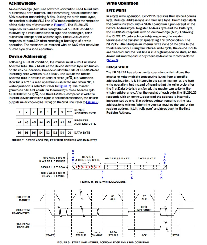
ISL29125 I²C Communication Protocol, the core content includes: it performs addressing via the device address (fixed upper 7 bits 1000100 + read/write bit), after the master initiates a start condition, it sends the device address, register address and data bytes in sequence, and the slave pulls low SDA to generate ACK signal to confirm reception; it supports single-byte write and continuous burst write, during burst write the address pointer automatically increments, during data writing SDA enters a high-impedance state, the communication ends with a stop condition, and the timing definitions for start, data stability, acknowledge and stop are also provided.
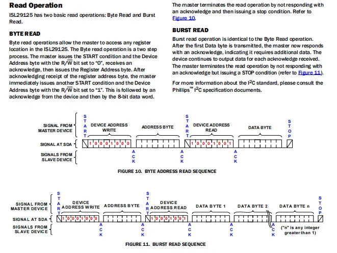
ISL29125 supports two types of I²C read operations: Single-byte read requires writing the register address first then switching to read mode; after receiving 1 byte of data, the master terminates the operation with a NACK + stop condition;Burst read is based on the single-byte read: the master sends an ACK after receiving each 1 byte of data to make the device continuously output data from multiple registers, until the master terminates the transmission with a NACK + stop condition.
2.8 PCB Routing Precautions
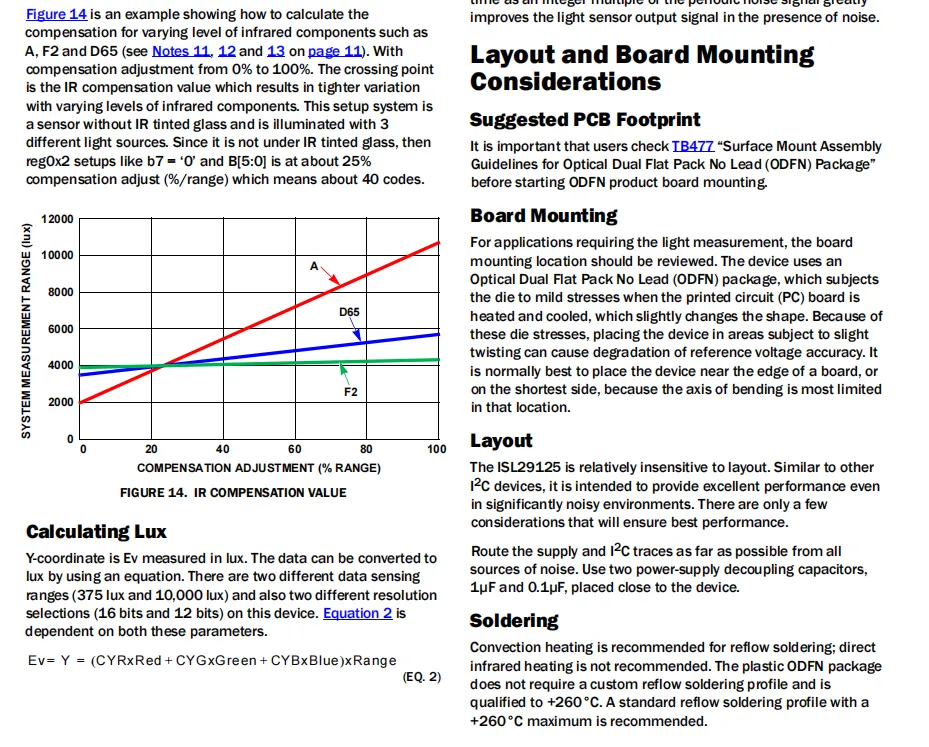
ISL29125 adopts the ODFN package, which is not sensitive to PCB layout; however, the power supply and I²C traces should be kept away from noise sources, and 1μF and 0.1μF power supply decoupling capacitors need to be placed near the device. During installation, it is recommended to place the device at the edge of the PCB to reduce the impact of bending stress; for soldering, convection heating reflow soldering is recommended, and direct infrared heating should be avoided.
III. Circuit Engineering
3.1 Circuit Source Engineering
To obtain the source code of the circuit, please follow the official account [Freak Embedded]
3.2 Module Usage Instructions
The schematic diagram of this module is shown below:
SCH_Schematic1_Color Sensor Module Based on ISL29125_v1.0.0_2026-05-07.pdf 2.1 MB
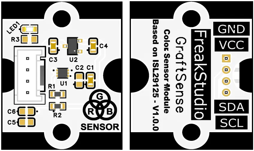
This module provides a IIC communication interface: it supports standard I2C communication rates, is compatible with 3.3V logic level, and can stably transmit the 16-bit digital signals of red, green and blue light intensity collected by ISL29125. It is applicable to scenarios such as color detection, light source identification and ambient light monitoring, and provides reliable color perception data interaction capability for the system.
3.3 Application Experiment
Here, we use the GraftPort-RP2040 development board for testing. The ISL29125-based color sensor module communicates with the main controller via the I2C interface.
Here, we first use the HY2.0-4P cable to connect the module to the GraftPort-RP2040 development board's I2C0 interface:
Development Board Pins | Module Pins | Description |
Pin 4 |
|
|
Pin 5 |
|
|
Here, we need to search for the relevant driver packages on uPyPI: https://upypi.net/zh/
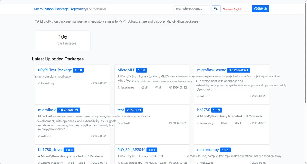
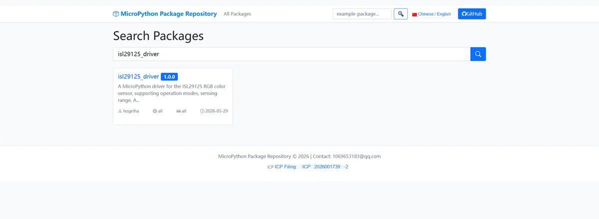
Enter isl29125_driver to search, and the following will be displayed:
Click to copy the local installation command:
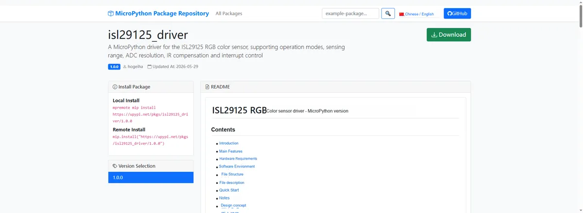
Import the module driver library code via the mip tool. Below are the usage commands for the mpremote tool:
mpremote mip install https://upypi.net/pkgs/isl29125_driver/1.0.0Import the color sensor module based on ISL29125 - MicroPython driver code, then copy the following main.py code into our project:
# Python env   : MicroPython v1.23.0
# -*- coding: utf-8 -*-
# @Time    : 2026/4/21 20:00
# @Author  : FreakStudio
# @File    : main.py
# @Description : Test ISL29125 RGB color sensor driver, demonstrating color reading, mode configuration and color recognition
# @License : MIT

# ======================================== Import Modules =========================================

from machine import Pin, SoftI2C
from micropython_isl29125 import isl29125
import time

# ======================================== Global Variables ============================================

# I2C pin and frequency configuration
I2C_SDA_PIN = 4
I2C_SCL_PIN = 5
I2C_FREQ = 100_000

# Target sensor I2C address list
TARGET_SENSOR_ADDRS = [0x44]

# Expected chip ID (used for ID verification)
EXPECTED_CHIP_ID = 0x7D

# Measurement loop delay (milliseconds)
MEAS_DELAY_MS = 500

# ======================================== Functions ============================================

def recognize_color(red: int, green: int, blue: int) -> str:
    """
    Recognize basic colors from the sensor's raw RGB values
    Args:
        red (int): raw red value, non-negative integer
        green (int): raw green value, non-negative integer
        blue (int): raw blue value, non-negative integer
    Returns:
        str: color name string
    Raises:
        TypeError: parameter type is not int
        ValueError: parameter is negative
    Notes:
        Uses normalized ratio thresholds for judgment, supports Black/Red/Green/Blue/Yellow/White/Unknown
    ==========================================
    Identify basic color from raw RGB sensor values.
    Args:
        red (int): Raw red value, non-negative integer
        green (int): Raw green value, non-negative integer
        blue (int): Raw blue value, non-negative integer
    Returns:
        str: Color name string
    Raises:
        TypeError: Parameter type is not int
        ValueError: Parameter is negative
    Notes:
        Uses normalized ratio thresholds; supports Black/Red/Green/Blue/Yellow/White/Unknown
    """
    for val, name in ((red, "red"), (green, "green"), (blue, "blue")):
        if not isinstance(val, int):
            raise TypeError("%s must be int, got %s" % (name, type(val).__name__))
        if val < 0:
            raise ValueError("%s cannot be negative, got %d" % (name, val))
    total = red + green + blue
    if total < 50:
        return "Black/No light"
    r_ratio = red / total
    g_ratio = green / total
    b_ratio = blue / total
    if r_ratio > 0.6:
        return "Red"
    elif g_ratio > 0.6:
        return "Green"
    elif b_ratio > 0.6:
        return "Blue"
    elif r_ratio > 0.4 and g_ratio > 0.4:
        return "Yellow"
    elif r_ratio > 0.3 and g_ratio > 0.3 and b_ratio > 0.3:
        return "White"
    return "Unknown"


def test_config(sen) -> None:
    """Print the sensor's current configuration"""
    print("Operation mode: %s" % sen.operation_mode)
    print("Sensing range: %s" % sen.sensing_range)
    print("ADC resolution: %s" % sen.adc_resolution)
    print(50 * "-")


def test_boundary_values(sen) -> None:
    """
    Boundary parameter test: verify extreme value settings for range, resolution and interrupt threshold.

    Args:
        sen: ISL29125 sensor instance
    Returns:
        None
    """
    print("--- Boundary value test ---")

    # Test range switching boundaries
    sen.sensing_range = isl29125.LUX_375
    print("sensing_range -> LUX_375: %s" % sen.sensing_range)
    sen.sensing_range = isl29125.LUX_10K
    print("sensing_range -> LUX_10K: %s" % sen.sensing_range)

    # Test ADC resolution boundaries
    sen.adc_resolution = isl29125.RES_12BITS
    print("adc_resolution -> RES_12BITS: %s" % sen.adc_resolution)
    sen.adc_resolution = isl29125.RES_16BITS
    print("adc_resolution -> RES_16BITS: %s" % sen.adc_resolution)

    # Test interrupt threshold extreme values
    sen.high_threshold = 32767
    sen.low_threshold = 0
    print("high_threshold=32767, low_threshold=0 set OK")

    print("--- Boundary value test passed ---")


def test_exception_values(sen) -> None:
    """
    Exception parameter test: verify that illegal values correctly raise exceptions.

    Args:
        sen: ISL29125 sensor instance
    Returns:
        None
    """
    print("--- Exception value test ---")

    # Test illegal operating mode
    try:
        sen.operation_mode = 99
        print("FAIL: should have raised ValueError")
    except ValueError as e:
        print("OK: operation_mode=99 -> ValueError: %s" % str(e))

    # Test illegal range
    try:
        sen.sensing_range = 99
        print("FAIL: should have raised ValueError")
    except ValueError as e:
        print("OK: sensing_range=99 -> ValueError: %s" % str(e))

    # Test illegal IR compensation value
    try:
        sen.ir_compensation_value = 99
        print("FAIL: should have raised ValueError")
    except ValueError as e:
        print("OK: ir_compensation_value=99 -> ValueError: %s" % str(e))

    # Test recognize_color illegal type
    try:
        recognize_color("a", 0, 0)
        print("FAIL: should have raised TypeError")
    except TypeError as e:
        print("OK: recognize_color('a',0,0) -> TypeError: %s" % str(e))

    # Test recognize_color negative parameter
    try:
        recognize_color(-1, 0, 0)
        print("FAIL: should have raised ValueError")
    except ValueError as e:
        print("OK: recognize_color(-1,0,0) -> ValueError: %s" % str(e))

    print("--- Exception value test passed ---")

# ======================================== Custom Classes ============================================

# ======================================== Initialization ==========================================

time.sleep(3)
print("FreakStudio: ISL29125 color sensor test starting ...")

# Initialize I2C bus
i2c_bus = SoftI2C(sda=Pin(I2C_SDA_PIN), scl=Pin(I2C_SCL_PIN), freq=I2C_FREQ)

# Scan the I2C bus
devices_list = i2c_bus.scan()
print("I2C scan result: %s" % [hex(d) for d in devices_list])

if len(devices_list) == 0:
    raise RuntimeError("I2C scan found no devices")

# Find the target sensor address
sensor = None
for device_addr in devices_list:
    if device_addr in TARGET_SENSOR_ADDRS:
        print("Target sensor found at address: %s" % hex(device_addr))
        sensor = isl29125.ISL29125(i2c=i2c_bus, address=device_addr)
        break

if sensor is None:
    raise RuntimeError("Target sensor not found on I2C bus")

# Verify chip ID
chip_id = sensor._device_id
print("Chip ID: %s (expected: %s)" % (hex(chip_id), hex(EXPECTED_CHIP_ID)))
if chip_id != EXPECTED_CHIP_ID:
    raise RuntimeError("Chip ID mismatch: got %s, expected %s" % (hex(chip_id), hex(EXPECTED_CHIP_ID)))

# Configure sensor
sensor.operation_mode = isl29125.RED_GREEN_BLUE
sensor.sensing_range  = isl29125.LUX_10K
sensor.adc_resolution = isl29125.RES_16BITS
sensor.clear_register_flag()
test_config(sensor)

# Run boundary value tests
test_boundary_values(sensor)
print(50 * "-")

# Run exception parameter tests
test_exception_values(sensor)
print(50 * "-")

# ========================================  Main Program  ===========================================

try:
    while True:
        # Read raw values of the RGB three channels
        r, g, b = sensor.colors
        # Recognize color
        color_name = recognize_color(r, g, b)
        print("R:%5d | G:%5d | B:%5d | Detected: %s" % (r, g, b, color_name))
        time.sleep_ms(MEAS_DELAY_MS)

except KeyboardInterrupt:
    print("Program interrupted by user")
except OSError as e:
    print("Hardware communication error: %s" % str(e))
except Exception as e:
    print("Unknown error: %s" % str(e))
finally:
    print("Cleaning up resources...")
    sensor.deinit()
    del sensor
    print("Program exited")
Burn the code, open the terminal, and the output is as follows:
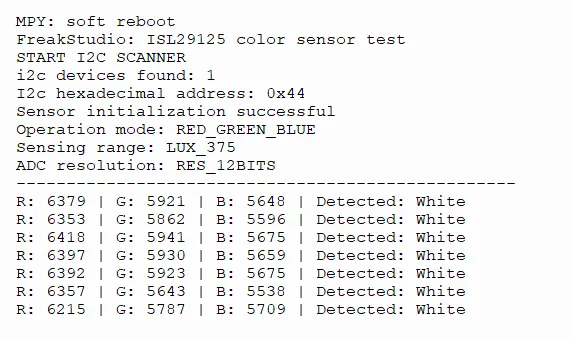
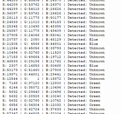
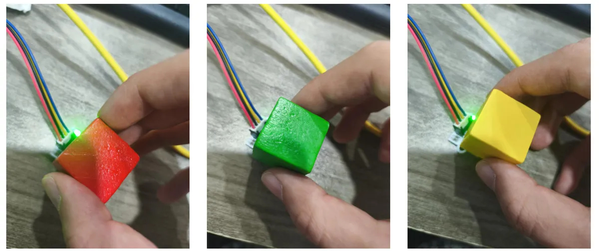
It can be seen that ISL29125 color sensor has normal I2C communication and initialization, and can stably output ADC data of RGB channels; when testing objects of different colors, it can identify the corresponding colors, but in some scenarios, the judgment of "Unknown" will appear due to the influence of ambient light, and the detection accuracy is affected by the actual light.
IV. Drivers
isl29125_driver-1.0.0.zip 13 KB
5. BOM & Recommended Alternative Parts
None.
VI. Revision History
Document Version | Date Modified | Modifier | Modify Content |
v1.0 | 2026-05-07 | Ling Gaoxing | Initialize the document |
v1.1 | 2026-06-06 | Xin Ruili | Create an open version of the document based on the internal document version v1.0. |
7. Relevant Materials
7.1 Chip Datasheet
ISL29125.pdf 903 KB
7.2 Unique Icons for PCB Silk Screen