Contents
- I. Module Introduction
- II. Introduction to Main Chips
- 2.1 Chip Overview
- 2.2 Pin Definition
- 2.3 Functional Block Diagram
- 2.4 Performance Parameters
- 2.5 Reference Circuit
- 2.6 Chip Configuration
- 2.7 Communication Interfaces and Related Protocols
- 2.8 PCB Routing Precautions
- III. Circuit Engineering
- 3.1 Circuit Source Engineering
- 3.2 Module Usage Instructions
- 3.3 Application Experiment
- IV. Drivers
- 5. BOM & Recommended Alternative Parts
- VI. Revision History
- 7. Relevant Materials
- 7.1 Chip Datasheet
- 7.2 Unique Icons for PCB Silk Screen
I. Module Introduction
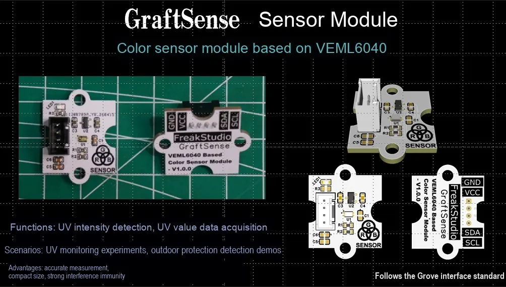
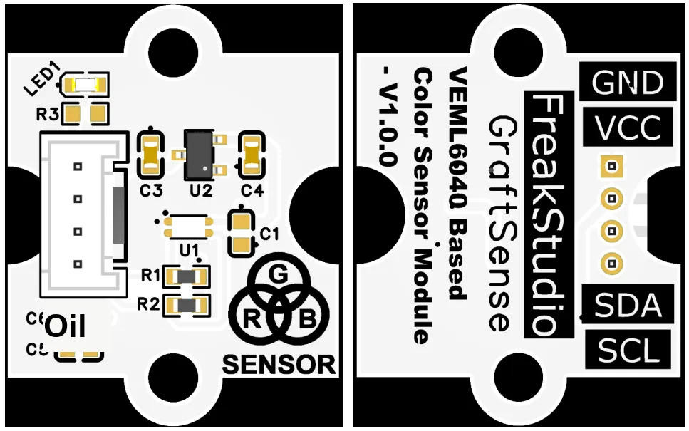
A color sensor module based on the VEML6040, which adopts the VEML6040 chip solution, supports I2C communication, can convert the intensity of red, green, blue and white light into 16-bit digital signal output, and realizes high-precision color detection;The module is equipped with LDO voltage regulator circuits, power filtering and indicator light circuits, powered by 3.3V, and features low power consumption (typical current of 450μA in active mode, only 0.5μA in shutdown mode). It can also effectively filter out 50Hz/60Hz light flicker noise, maintain stable detection under different lighting environments, and is suitable for scenarios such as color recognition, ambient light monitoring, and handheld devices.
II. Introduction to Main Chips
VEML6040 is a low-power digital Filtron technology-based RGBW color sensor that supports I2C communication, outputs 16-bit red, green, blue and white light intensity data, and integrates built-in flicker noise cancellation, making it suitable for color and ambient light detection scenarios.
2.1 Chip Overview
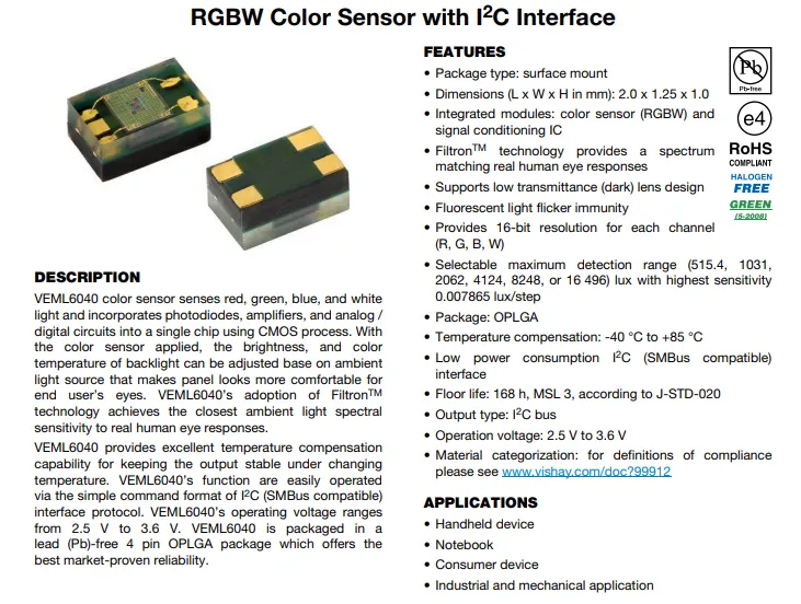
VEML6040 is an integrated I²C interface-based RGBW color sensor, housed in an OPLGA package with dimensions of 2.0×1.25×1.0mm. Built with Filtron™ technology, it features a spectral response matching the human eye, 16-bit resolution, selectable measurement range, temperature compensation, anti-fluorescent flicker and low power consumption, and is suitable for color and ambient light detection in scenarios such as consumer electronics and industrial equipment.
2.2 Pin Definition

VEML6040 Pin Definition and Internal Structure: It has 4 pins, namely GND (Ground), SDAT (I²C data bus, open-drain bidirectional), SCLK (I²C clock input) and VDD (Power Supply); it integrates red, green, blue and white four-channel photodiodes inside, and realizes the acquisition and digital output of color and ambient light signals through the control logic and I²C output buffer.
2.3 Functional Block Diagram
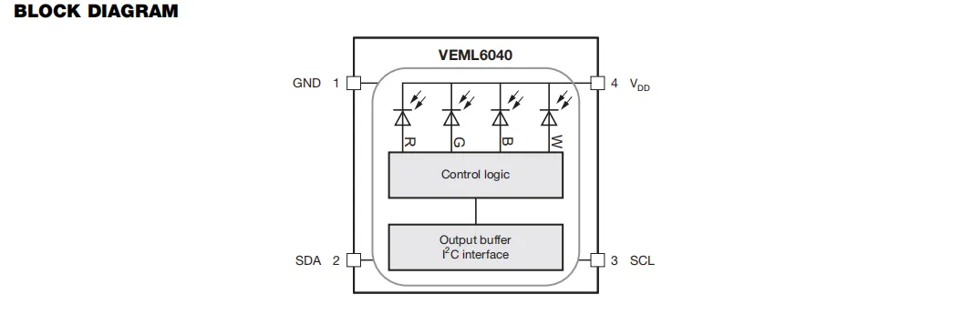
The VEML6040 sensor collects incident light signals through its built-in four-channel photodiodes for red, green, blue and white. After being processed by the control logic, the processed digital signals are transmitted to the host via the I²C interface output buffer through the SDA and SCL pins, so as to realize the detection of ambient light color and brightness.
2.4 Performance Parameters
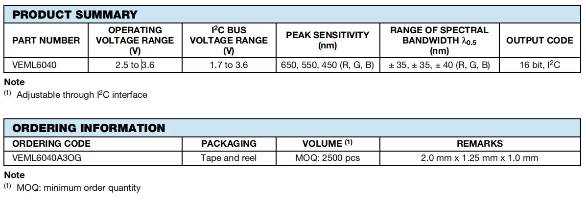
VEML6040 operates at a supply voltage of 2.5~3.6V, I²C bus voltage ranges from 1.7 to 3.6V. The peak sensitivities of its red, green and blue channels are around 650nm, 550nm and 450nm respectively, with a spectral bandwidth matching the human eye response. It outputs 16-bit digital signals transmitted via the I²C interface;
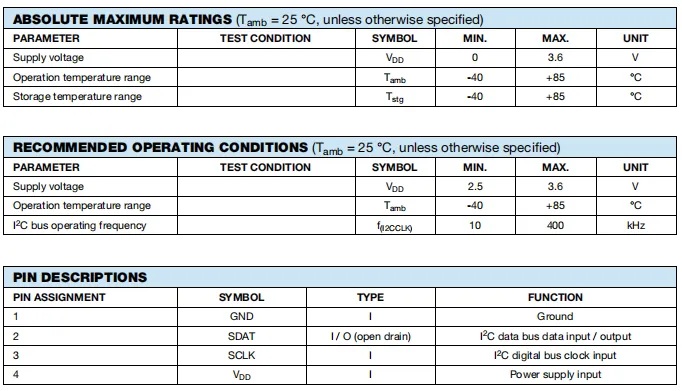
Among the absolute maximum ratings, the maximum power supply voltage is 3.6V, and both the operating and storage temperature ranges are -40 to + 85°C;
Under recommended operating conditions, the power supply voltage ranges from 2.5V to 3.6V, I²C bus frequency supports 10kHz to 400kHz; in terms of pins, Pin 1 is ground, Pin 2 is an open-drain I²C data port, Pin 3 is the I²C clock input, and Pin 4 is the power supply input.
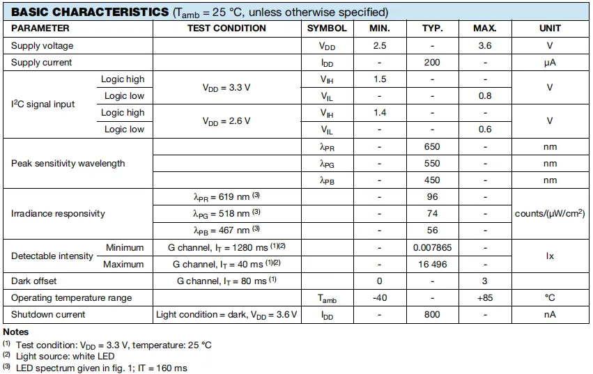
VEML6040 Basic electrical and optical characteristics at 25°C: supply voltage 2.5-3.6V, typical operating current 200μA, and shutdown current as low as 800nA;I²C input levels have clear thresholds corresponding to the supply voltage; the peak sensitivity wavelengths of the red, green and blue channels are 650nm, 550nm and 450nm respectively, with corresponding irradiance responsivities of 96,74 and 56 counts/(μW/cm²);It also specifies the detectable illuminance range (0.007865–16496 lx), dark offset (≤3 counts), and operating temperature range of -40 to + 85 °C.
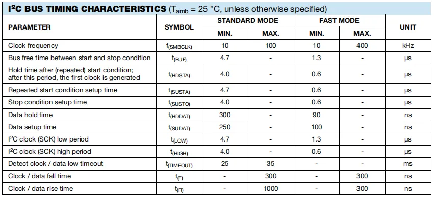
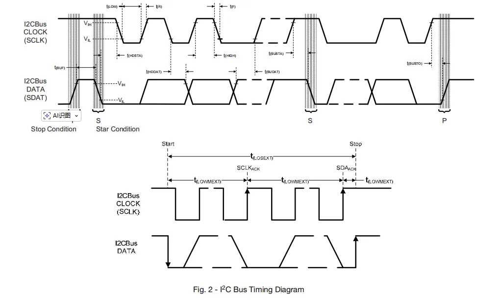
The VEML6040 sensor's I²C bus timing parameters define key specifications including clock frequency, bus idle time, timing for start/repeated start/stop conditions, data setup/hold time, clock high/low pulse width, signal rise/fall time and timeout detection under both standard mode (10-100kHz) and fast mode (10-400kHz), providing a compliance basis for I²C communication stability.
2.5 Reference Circuit
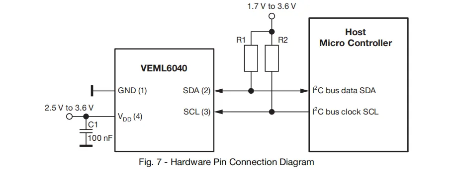
The VDD pin of the sensor is connected to a 2.5-3.6V power supply and decoupled via a 100nF capacitor, while the GND pin is grounded; the I²C interface's SDA and SCL pins are connected to the host controller via pull-up resistors R1 and R2 (connected to 1.7-3.6V) to enable communication with the MCU.
2.6 Chip Configuration
None.
2.7 Communication Interfaces and Related Protocols
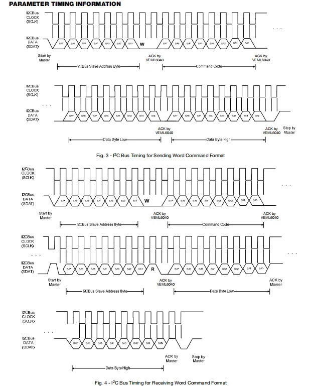
VEML6040 I²C communication timing: When transmitting a word command, the master first sends the slave address (with write bit) and command code, then consecutively transmits the low and high bytes of data, and the sensor responds with ACK; when receiving a word command, the master first sends the slave address (write bit) and command code, then switches to read mode via a repeated start, reads the low and high bytes of data in sequence, and finally the master sends NACK and a stop signal.
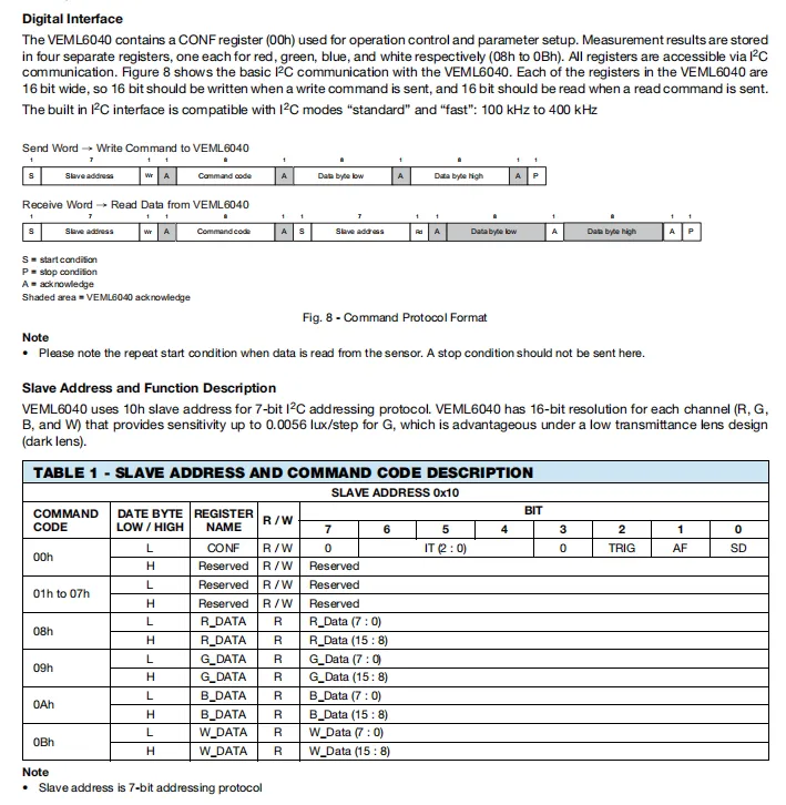
VEML6040 Digital Interface and Register Definition: It supports I²C communication compatible with standard/fast mode (100-400kHz), supports transmit/receive word command format, and its 7-bit slave address is 0x10; For registers, 0x00h is the read-write CONF control register, and 0x08h - 0x0Bh are the 16-bit read-only data registers for red, green, blue and white channels respectively, with measurement results stored in low-byte and high-byte order.
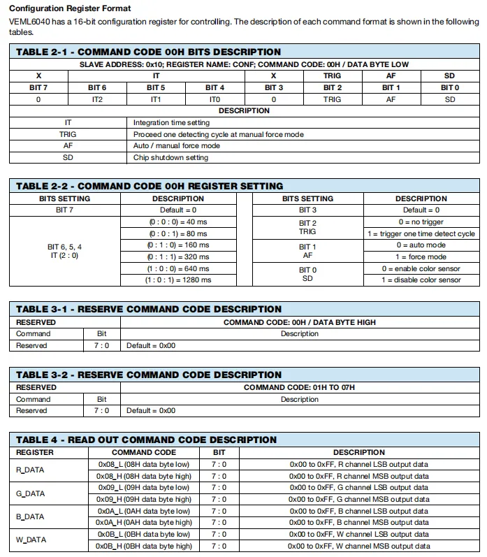
VEML6040) can set the integration time to 40/80/160/320/640/1280ms;IT bits (BIT6-4) in the low byte of the 16-bit configuration register (0x00) can set the integration time to 40/80/160/320/640/1280ms;TRIG (BIT2) is used to manually trigger a single measurement;AF (BIT1) switches between auto/forced mode;SD (BIT0) controls the chip's start/stop; the high byte and registers 0x01 - 0x07 are reserved bits.0x08 - 0x0B are the 16-bit read-only data registers for the red, green, blue and white channels respectively, which store the measurement results of each channel.
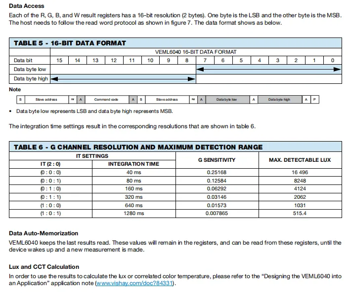
VEML6040 Data Format and Performance Parameters: The four-channel measurement results are all 16-bit (the low byte is LSB, and the high byte is MSB), which need to be read in accordance with the read word protocol; different integration times (40-1280ms) correspond to different G channel sensitivities and maximum detection illuminance. The longer the integration time, the higher the sensitivity and the smaller the measurement range; the chip will automatically save the last measurement data until a new measurement is completed. For calculating illuminance and color temperature, please refer to the corresponding application note document.
2.8 PCB Routing Precautions
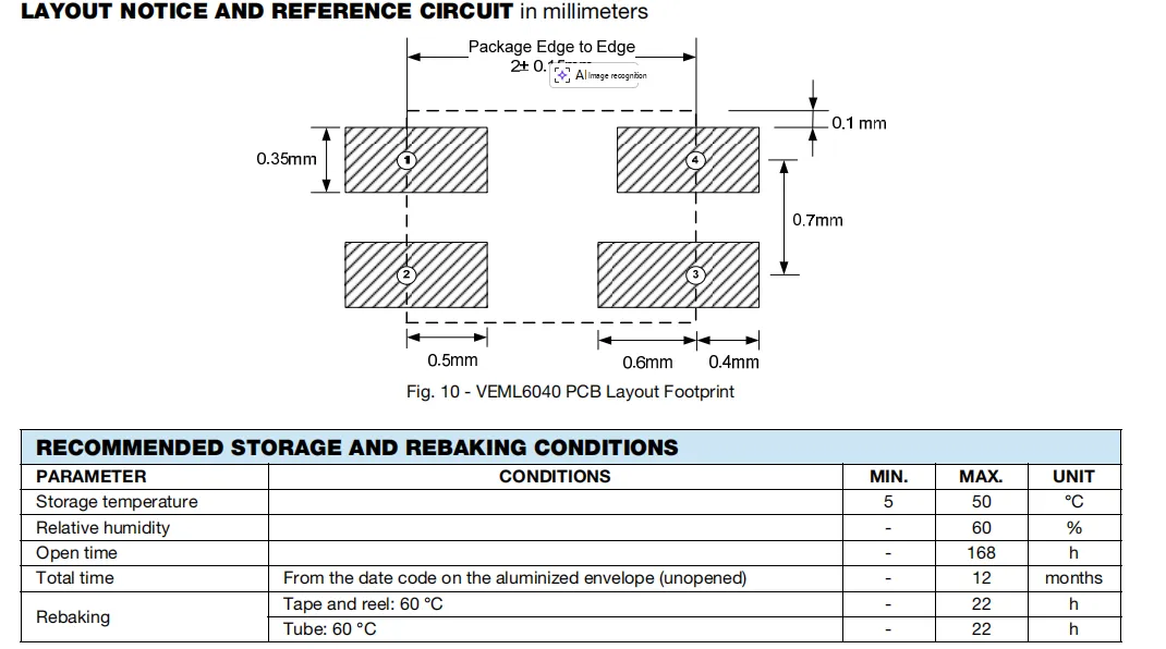
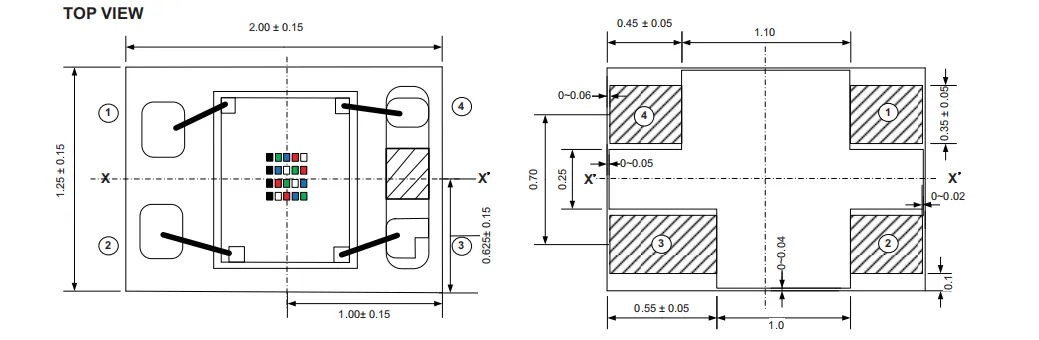
VEML6040 PCB Pad Layout and Storage Conditions: The upper part shows a dimensioned design drawing of the 4-pin pad, which specifies the spacing, dimensions and tolerances of each pad; the table below lists the recommended storage conditions: temperature 5-50℃, humidity ≤60%, storage time after opening not exceeding 168 hours, unopened shelf life of 12 months, and re-baking condition of 60℃ for 22 hours.
III. Circuit Engineering
3.1 Circuit Source Engineering
To obtain the source code of the circuit, please follow the official account [Freak Embedded]
3.2 Module Usage Instructions
The schematic diagram of this module is shown below:
SCH_Schematic1_Color Sensor Module Based on VEML6040_1.0.0_2026-05-07.pdf 2.0 MB
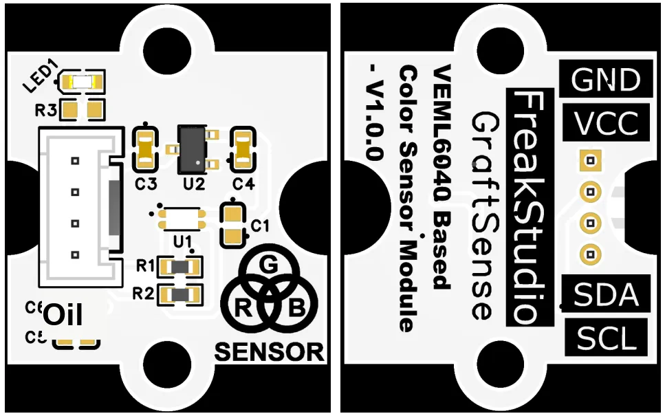
This module provides an IIC communication interface: it supports standard I2C communication rates, is compatible with 3.3V logic level, can stably transmit the 16-bit digital signals of red, green, blue and white light intensity collected by VEML6040, is suitable for scenarios such as color recognition and ambient light monitoring, and provides the system with reliable data interaction capability for color and light intensity sensing.
3.3 Application Experiment
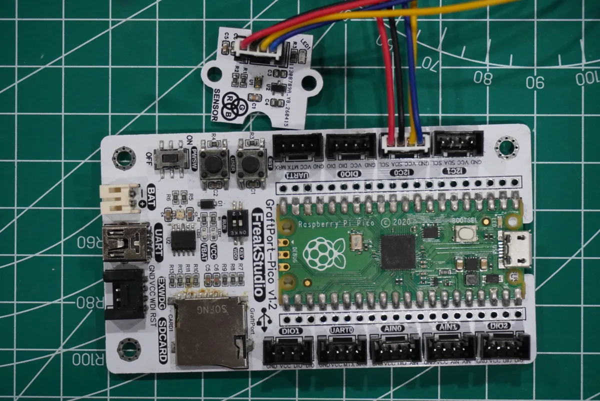
Here, we use the GraftPort-RP2040 development board for testing, and the VEML6040-based color sensor module communicates with the main controller via the I2C interface.
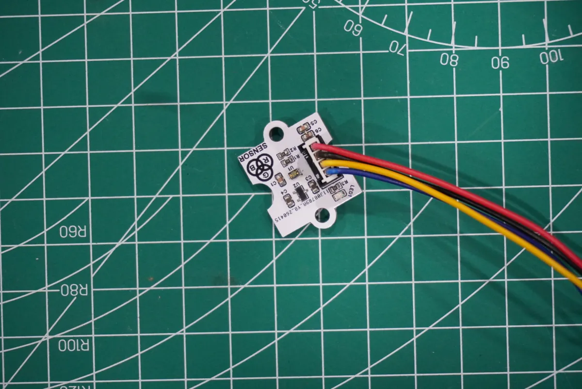
Here, we first use the HY2.0-4P cable to connect the module to the GraftPort-RP2040 development board's I2C0 interface:
Development Board Pins | Module Pins | Description |
Pin 4 |
|
|
Pin 5 |
|
|
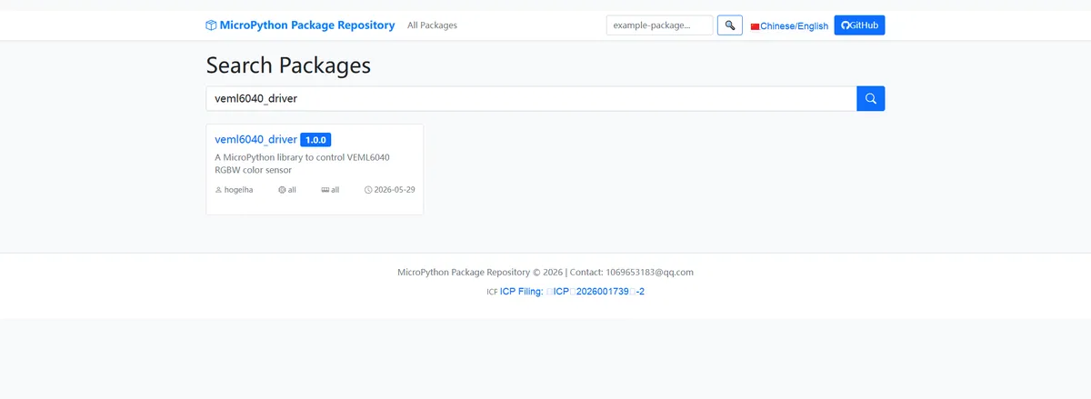
Here, we need to search for the relevant driver packages on uPyPI: https://upypi.net/zh/
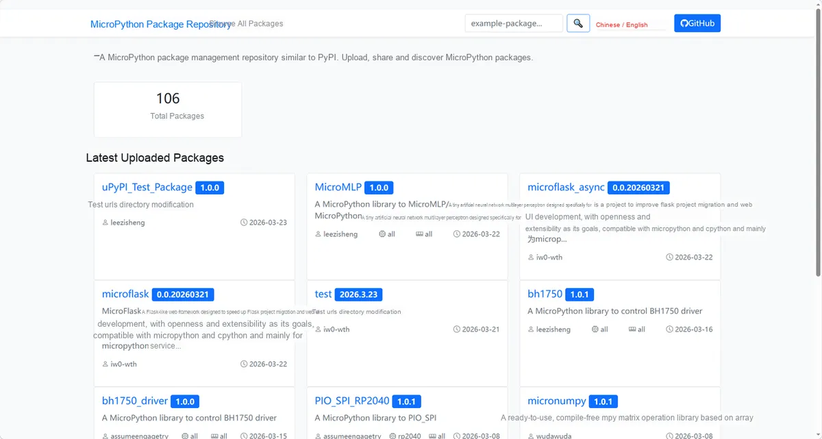
Enter veml6040_driver to search, and the following will be displayed:
Click to copy the local installation command:
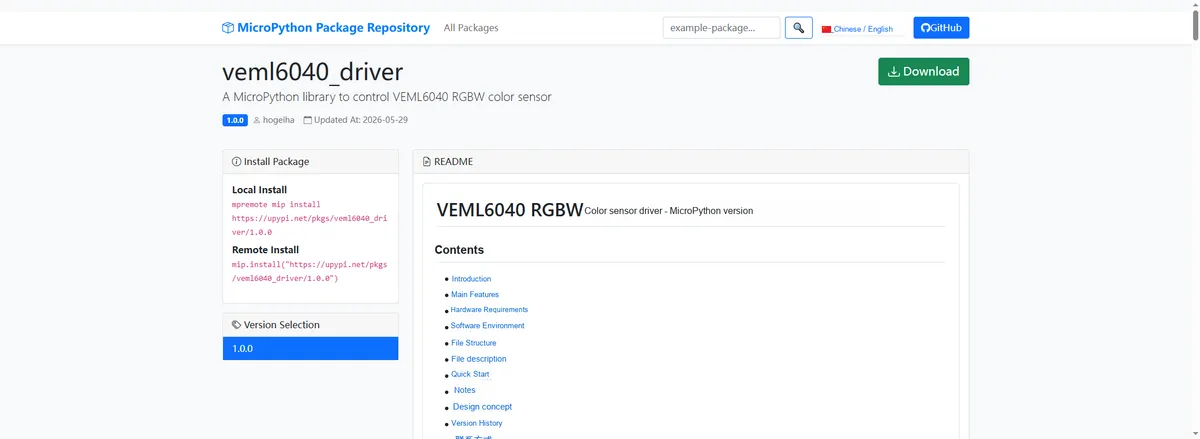
Import the module driver library code via the mip tool. Below are the usage commands for the mpremote tool:
mpremote mip install https://upypi.net/pkgs/veml6040_driver/1.0.0Import the MicroPython driver code for the VEML6040-based color sensor module, then copy the following main.py code into our project:
# Python env   : MicroPython v1.23.0
# -*- coding: utf-8 -*-
# @Time    : 2026/4/21 PM
# @Author  : FreakStudio
# @File    : main.py
# @Description : VEML6040 RGBW color sensor reading example

# ======================================== Import Modules =========================================

from machine import I2C, Pin
from sensor_pack_2.bus_service import I2cAdapter
from veml6040mod import VEML6040, get_g_max_lux
import time

# ======================================== Global Variables ============================================

# VEML6040 default I2C address
TARGET_SENSOR_ADDRS = [0x10]

# I2C data line connected to Pico GPIO4
I2C_SDA_PIN = 4

# I2C clock line connected to Pico GPIO5
I2C_SCL_PIN = 5

# I2C communication frequency set to 400kHz
I2C_FREQ = 400000

# Integration time configured to 80ms
INTEGRATION_TIME = 1

# ======================================== Functions ============================================


def get_als_lux(green_channel: int, sensitivity: float) -> float:
    """
    Calculate ambient illuminance from the green channel.
    Args:
        green_channel (int): raw green channel value.
        sensitivity (float): sensitivity corresponding to the current integration time.

    Raises:
        ValueError: raised when the parameter is empty or has an illegal value.
        TypeError: raised when the parameter type is illegal.

    Notes:
        VEML6040 uses the green channel to estimate ambient illuminance.

    ==========================================
    Calculate ambient light lux from green channel.
    Args:
        green_channel (int): Green channel raw value.
        sensitivity (float): Sensitivity for current integration time.

    Raises:
        ValueError: Raised when parameter is None or invalid.
        TypeError: Raised when parameter type is invalid.

    Notes:
        VEML6040 estimates ambient lux from green channel.
    """
    if green_channel is None:
        raise ValueError("Green channel cannot be None")

    if sensitivity is None:
        raise ValueError("Sensitivity cannot be None")

    if not isinstance(green_channel, int):
        raise TypeError("Green channel must be integer")

    if sensitivity < 0:
        raise ValueError("Sensitivity must not be negative")

    return sensitivity * green_channel


def detect_color(red: int, green: int, blue: int, white: int) -> str:
    """
    Recognize basic colors from the raw RGBW channels.
    Args:
        red (int): raw red channel value.
        green (int): raw green channel value.
        blue (int): raw blue channel value.
        white (int): raw white channel value.

    Raises:
        ValueError: raised when the parameter is empty or has an illegal value.
        TypeError: raised when the parameter type is illegal.

    Notes:
        This algorithm is for basic color judgment; in actual projects, thresholds can be calibrated for the light source and enclosure.

    ==========================================
    Detect basic color from RGBW raw channels.
    Args:
        red (int): Red channel raw value.
        green (int): Green channel raw value.
        blue (int): Blue channel raw value.
        white (int): White channel raw value.

    Raises:
        ValueError: Raised when parameter is None or invalid.
        TypeError: Raised when parameter type is invalid.

    Notes:
        This algorithm is for basic color detection and can be calibrated.
    """
    channels = (red, green, blue, white)

    for value in channels:
        if value is None:
            raise ValueError("Color channel cannot be None")

        if not isinstance(value, int):
            raise TypeError("Color channel must be integer")

        if value < 0:
            raise ValueError("Color channel must not be negative")

    rgb_max = max(red, green, blue)
    rgb_min = min(red, green, blue)
    rgb_sum = red + green + blue

    if white < 20 or rgb_max < 10:
        return "Black"

    if rgb_sum == 0:
        return "Black"

    balance = rgb_max - rgb_min

    if balance < rgb_max * 0.18:
        if white > rgb_max * 1.2:
            return "White"

        return "Gray"

    red_ratio = red / rgb_sum
    green_ratio = green / rgb_sum
    blue_ratio = blue / rgb_sum

    if red_ratio > 0.45 and green_ratio > 0.35:
        return "Yellow"

    if green_ratio > 0.42 and blue_ratio > 0.32:
        return "Cyan"

    if red_ratio > 0.42 and blue_ratio > 0.32:
        return "Magenta"


    if red_ratio > green_ratio and red_ratio > blue_ratio:
        return "Red"

    if green_ratio > red_ratio and green_ratio > blue_ratio:
        return "Green"

    if blue_ratio > red_ratio and blue_ratio > green_ratio:
        return "Blue"

    return "Unknown"


# ======================================== Custom Classes ============================================

# ======================================== Initialization configuration ===========================================

time.sleep(3)
print("FreakStudio: VEML6040 RGBW color sensor")

# Initialize I2C bus
i2c_bus = I2C(id=0, scl=Pin(I2C_SCL_PIN), sda=Pin(I2C_SDA_PIN), freq=I2C_FREQ)

# Scan I2C bus devices
devices_list = i2c_bus.scan()
print("START I2C SCANNER")

# Check whether any I2C device was found
if len(devices_list) == 0:
    print("No i2c device")
    raise SystemExit("I2C scan found no devices")

# Check whether the VEML6040 default address was found
if TARGET_SENSOR_ADDRS[0] not in devices_list:
    print("VEML6040 address not found")
    raise SystemExit("No VEML6040 device found")

# Print VEML6040 address
print("I2C hexadecimal address:", hex(TARGET_SENSOR_ADDRS[0]))

# Create I2C adapter
adapter = I2cAdapter(i2c_bus)

# Create VEML6040 sensor object
sensor = VEML6040(adapter)

# Make sure the sensor is in working state
if sensor.shutdown:
    sensor.shutdown = False

# Start single measurement mode
sensor.start_measurement(integr_time=INTEGRATION_TIME, auto_mode=False)

# Get measurement wait time
wait_time_ms = sensor.get_conversion_cycle_time()

# Get light sensitivity corresponding to the current integration time
green_sensitivity, max_lux = get_g_max_lux(sensor.integration_time)

# Print initialization information
print("Sensor initialization successful")
print("Integration time:", sensor.integration_time)
print("Wait time ms:", wait_time_ms)
print("Green sensitivity:", green_sensitivity)
print("Max detectable lux:", max_lux)

# ========================================  Main Program  ============================================

try:
    while True:
        # Wait for single measurement to complete
        time.sleep_ms(wait_time_ms)

        # Read raw RGBW channels
        red, green, blue, white = sensor.get_colors()

        # Calculate lux from the green channel
        lux = get_als_lux(green, green_sensitivity)

        # Recognize color from raw RGBW channels
        color_name = detect_color(red, green, blue, white)

        # Print color and illuminance data in English format
        print(
            "Red: {}  Green: {}  Blue: {}  White: {}  Lux: {:.2f}  Color: {}".format(
                red,
                green,
                blue,
                white,
                lux,
                color_name,
            )
        )

        # Start single measurement again
        sensor.start_measurement(integr_time=INTEGRATION_TIME, auto_mode=False)
except KeyboardInterrupt:
    # Turn off the sensor
    sensor.shutdown = True

    # Print the stop message
    print("Measurement stopped")
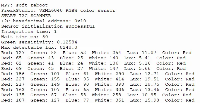
Burn the code, open the terminal, and the output is as follows:
Hold the color block close to the sensor (note: do not press it tightly against the sensor!):
Red color block:
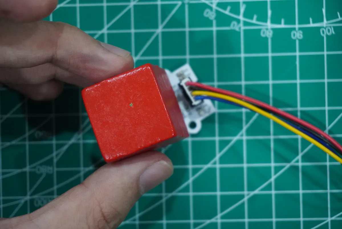
Green color block:
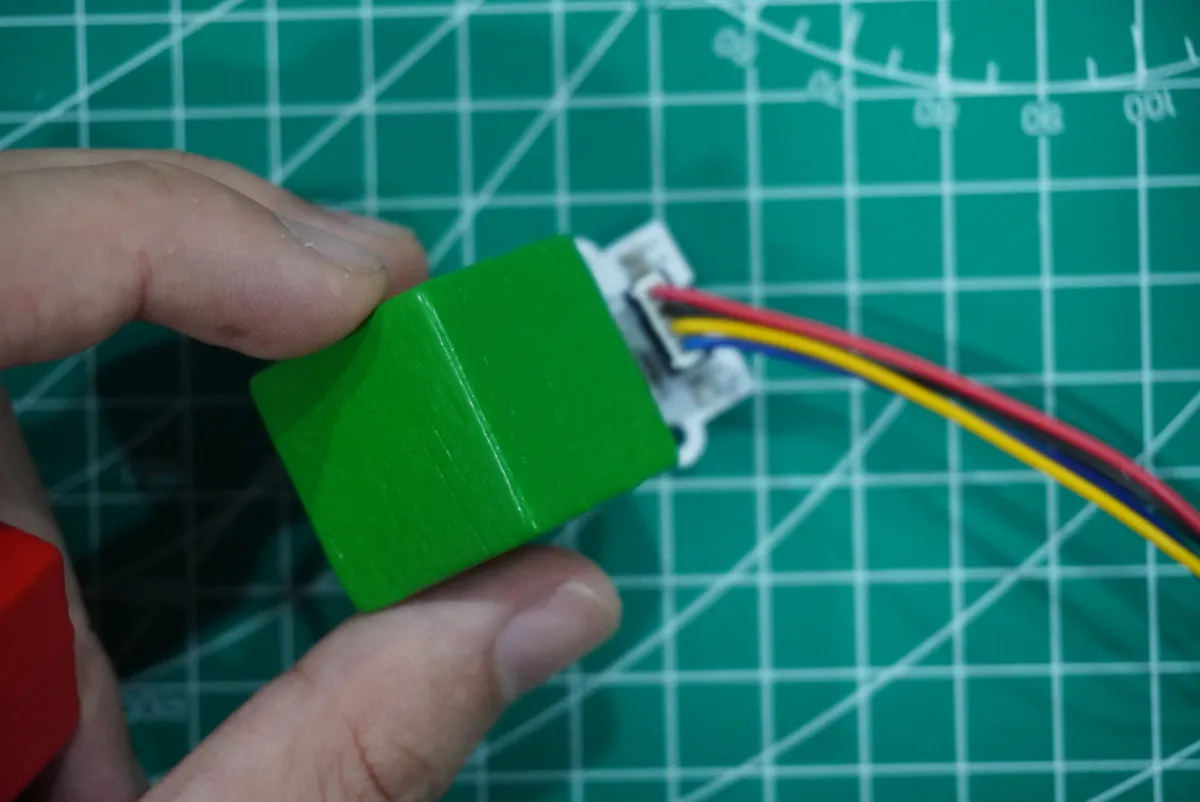
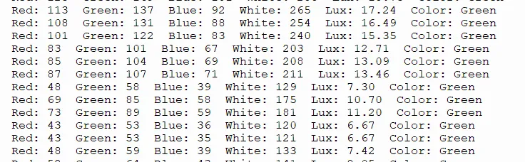
It can be seen from the example that colors are distinguished according to the RGB light intensity.
IV. Drivers
veml6040_driver-1.0.0.zip 21 KB
5. BOM & Recommended Alternative Parts
None.
VI. Revision History
Document Version | Date Modified | Modifier | Modify Content |
v1.0 | 2026-05-07 | Ling Gaoxing | Initialize the document |
v1.1 | 2026-06-06 | Xin Ruili | Create an open version of the document based on the internal document version v1.0. |
7. Relevant Materials
7.1 Chip Datasheet
VEML6040A3OG.pdf 392 KB
7.2 Unique Icons for PCB Silk Screen