Contents
- I. Module Introduction
- II. Introduction to Main Chips
- 2.1 Chip Overview
- 2.2 Pin Definition
- 2.3 Functional Block Diagram
- 2.4 Performance Parameters
- 2.5 Reference Circuit
- 2.6 Chip Configuration
- 2.7 Communication Interfaces and Related Protocols
- 2.8 PCB Routing Precautions
- III. Circuit Engineering
- 3.1 Circuit Source Engineering
- 3.2 Module Usage Instructions
- 3.3 Application Experiment
- IV. Drivers
- 5. BOM & Recommended Alternative Parts
- VI. Revision History
- 7. Relevant Materials
- 7.1 Chip Datasheet
- 7.2 Unique Icons for PCB Silk Screen
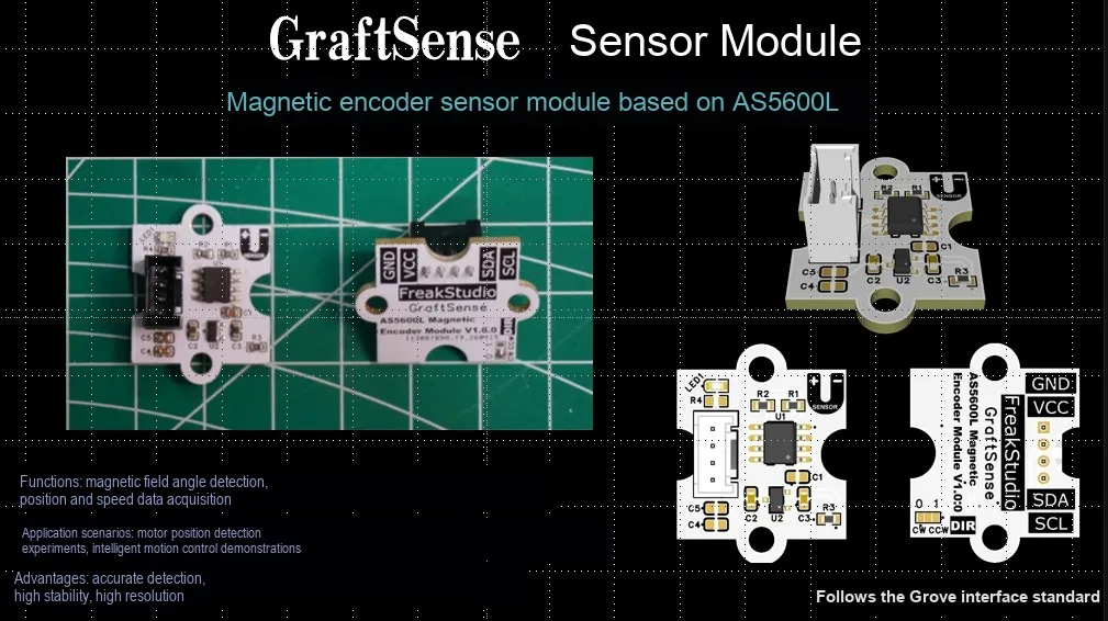
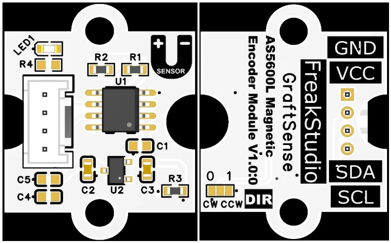
I. Module Introduction
AS5600L-based magnetic encoder sensor module, which adopts the AS5600L magnetic rotational position sensor solution, supports 360° non-contact angle measurement and provides 12-bit (4096 levels) high resolution position feedback; the module outputs digital signals via the I2C interface, and is equipped with an LDO voltage regulator circuit, power filtering and indicator circuit. It is powered by 3.3V, supports direction selection configuration, and has a built-in low-power mode, which can eliminate traditional mechanical wear and contact noise, and is suitable for angle detection scenarios such as motor control, robot joints, and industrial automation.
II. Introduction to Main Chips
AS5600L is a 12-bit contactless magnetic rotation position sensor launched by ams OSRAM, supporting I²C / PWM output, capable of measuring absolute angles from 0° to 360°, featuring programmability, low power consumption, and stray magnetic field resistance, and is available in SOIC-8 or WL-CSP packages.
2.1 Chip Overview
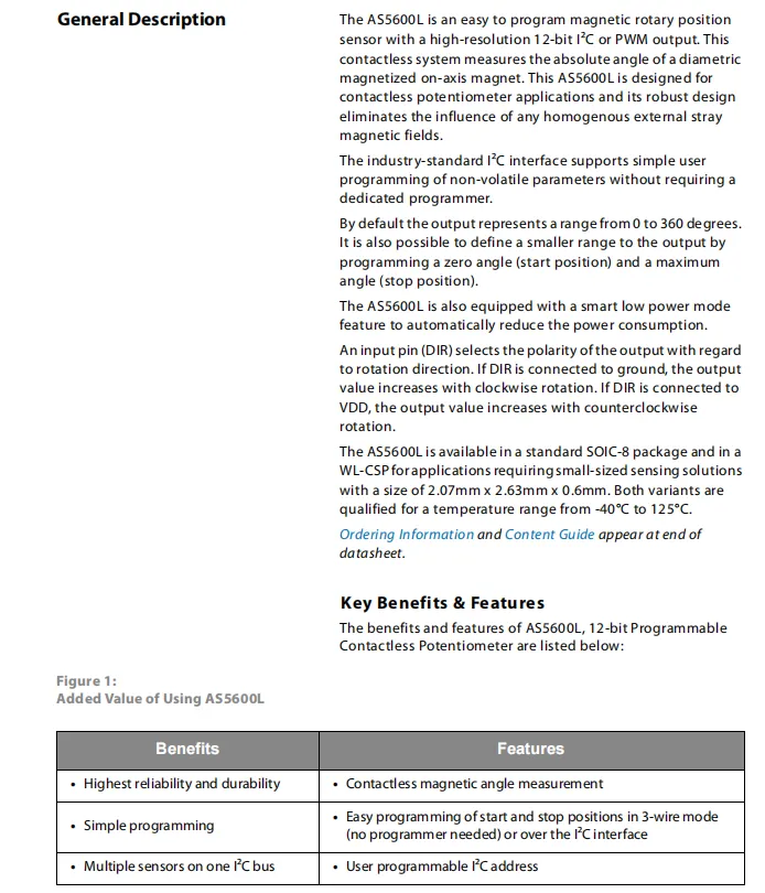
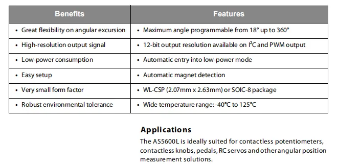
AS5600L is a 12-bit programmable non-contact magnetic rotational position sensor that supports I²C / PWM output, can measure absolute angles from 0° to 360°, features low power consumption, automatic magnet detection, and a wide operating temperature range (-40℃ to 125℃). It is available in two packages, SOIC-8 and WL-CSP, making it suitable for angle measurement scenarios such as contactless potentiometers, , and pedals.
2.2 Pin Definition
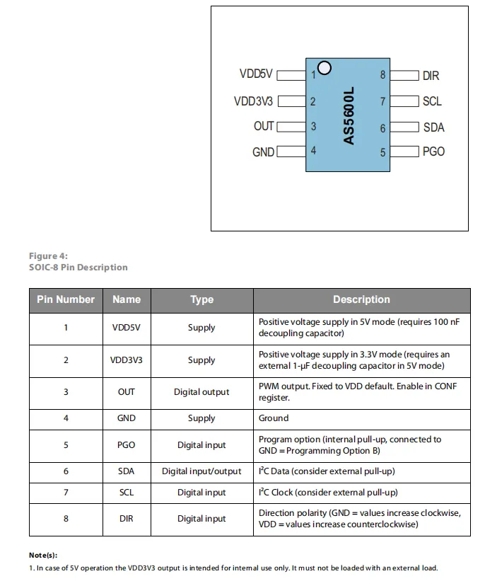
AS5600L SOIC-8 package pin assignment: Pin 1 VDD5V is 5V power supply, Pin 2 VDD3V3 is 3.3V power supply (an external 1μF decoupling capacitor is required in 5V mode), Pin 3 OUT is PWM output, Pin 4 GND is ground, Pin 5 PGO is programming option input, Pin 6 SDA and Pin 7 SCL are I²C interface, Pin 8 DIR is used to set output polarity direction.
2.3 Functional Block Diagram
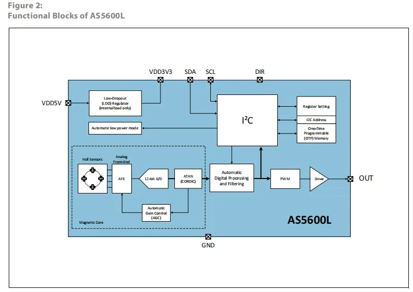
AS5600L collects magnetic field signals via a built-in Hall sensor, which, after processing by the analog front end, Automatic Gain Control and 12-bit analog-to-digital conversion, is then processed by the CORDIC algorithm to calculate the angle value; after further digital filtering processing, the result is finally output via I²C or PWM. Meanwhile, the built-in LDO, low-power control and OTP memory module realize power supply, power saving and parameter configuration.
2.4 Performance Parameters
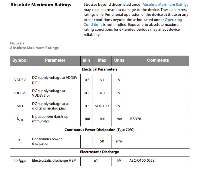
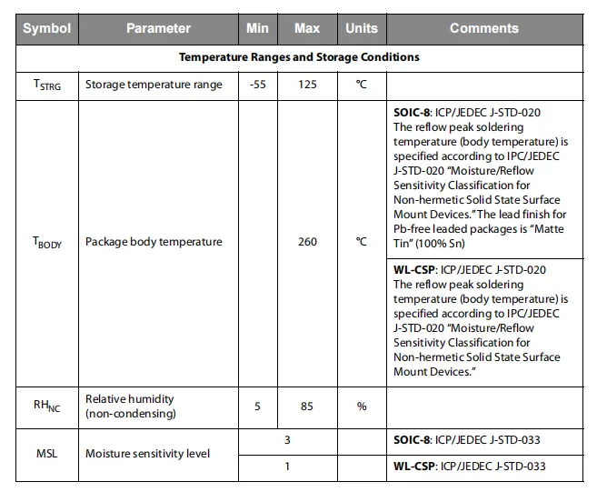
AS5600L Absolute Maximum Ratings and Environmental Conditions: In terms of electrical parameters, VDD5V has a maximum withstand voltage of 6.1 V, VDD3V3 has a maximum rating of 4.0 V, the voltage of digital/analog pins shall not exceed VDD + 0.3 V, the continuous power consumption shall not exceed 50 mW, and the HBM electrostatic protection is ±1 kV; in terms of environmental conditions, the storage temperature ranges from -55°C to 125°C, the peak reflow soldering temperature is 260°C, the operating humidity is 5-85% non-condensing, the moisture sensitivity level of the SOIC-8 package is level 3, and that of the WL-CSP package is level 1.
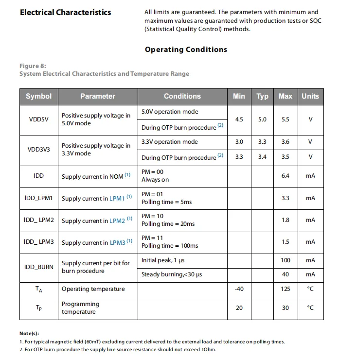
AS5600L Electrical Characteristics and Operating Conditions: The supply voltage ranges from 4.5 V to 5.5 V in 5.0 V mode, and from 3.0 V to 3.6 V in 3.3 V mode; the operating current varies from 1.5 mA to 6.4 mA in different low-power modes, and the peak current during OTP programming can reach 100 mA; the operating temperature range is -40°C to 125°C, while the programming temperature ranges from 20°C to 30°C.
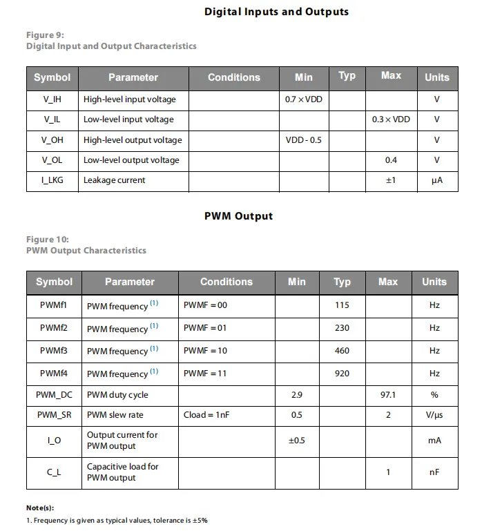
AS5600L 's digital I/O and PWM output characteristics: for digital input, high level ≥ 0.7× VDD, low level ≤ 0.3× VDD; for output, high level ≥ VDD - 0.5V, low level ≤ 0.4V, leakage current ±1μA;PWM output frequency can be configured within 115Hz~920Hz, duty cycle ranges from 2.9% to 97.1%, slew rate is 0.5~2V/μs, output current ±0.5mA, and the recommended load capacitance ≤ 1nF.
2.5 Reference Circuit
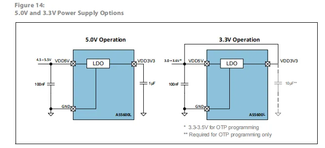
5V operation mode, the VDD5V pin is connected to a 4.5-5.5V power supply with a 100nF decoupling capacitor, the on-chip LDO generates a 3.3V voltage, and a 1μF capacitor is connected externally to the VDD3V3 pin;
In 3.3V operation mode, the VDD5V pin is directly connected to a 3.0-3.6V power supply, with a 100nF decoupling capacitor connected in parallel as well;the VDD3V3 pin only requires an external 10μF capacitor during OTP programming, and the on-chip LDO provides stable power supply for the circuit.
2.6 Chip Configuration
None.
2.7 Communication Interfaces and Related Protocols
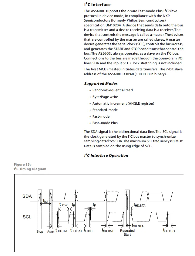
AS5600L operates as an I²C slave, supporting standard/fast/fast+ modes, with a 7-bit slave address of 0x40 and a maximum clock frequency of 1MHz. Data is sampled on the rising edge of SCL; the interface supports operations such as random/sequential read and byte/page write. The figure illustrates the I²C communication timing, including start, repeated start, stop and data timings.
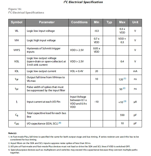
AS5600L I²C interface electrical parameters: low-level input voltage ≤ 0.3 × VDD, high-level input voltage ≥ 0.7 × VDD, Schmitt trigger hysteresis is 0.05 × VDD; open-drain output low-level voltage ≤ 0.4V (at 3mA sink current), sink current capability ≥ 20mA, output fall time 10~120ns; input current ±10μA, SDA / SCL pin capacitance ≤ 10pF, total bus load capacitance ≤ 550pF, the input filter can suppress spike interference within 50ns.
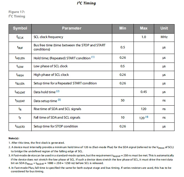
I²C timing parameters, which support a maximum clock frequency of 1 MHz, and specify key indicators including bus idle time, setup and hold times for start / repeated start / stop conditions, SCL high and low level widths, data setup / hold times, as well as the rise / fall times of SDA / SCL signals, providing a timing compliance basis for I²C communication.
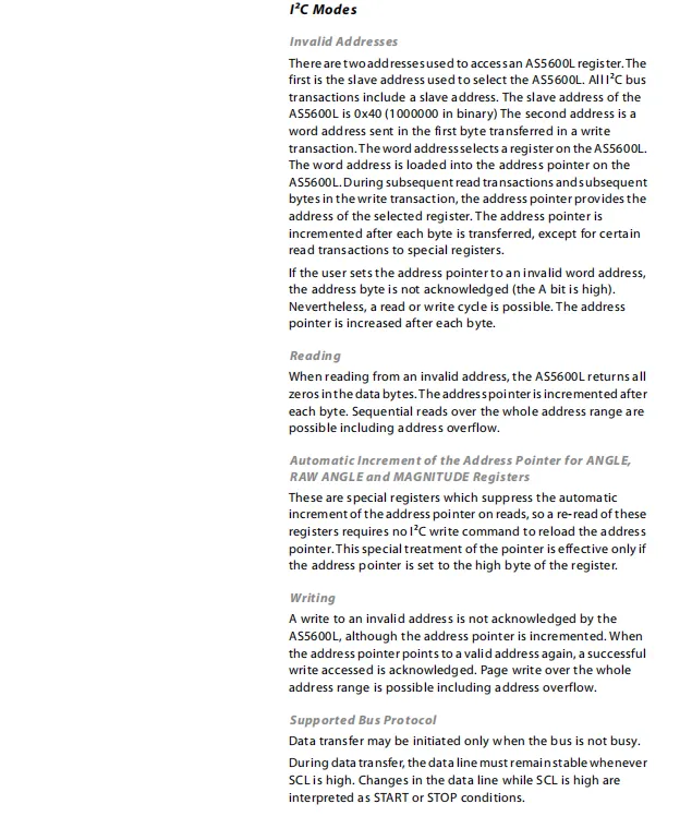
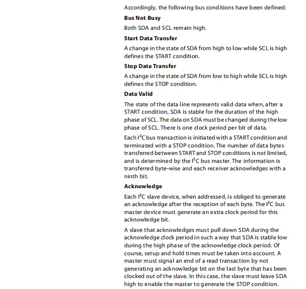
AS5600L I²C communication adopts the slave address 0x40, the register address pointer is set via a write operation, and this pointer will be automatically incremented in subsequent read and write operations; among them, the ANGLE, RAW ANGLE and MAGNITUDE registers will not be automatically incremented when being read;Communication must comply with the standard I²C protocol: when the bus is idle, both SDA and SCL are at high level; data transmission starts with the falling edge of SDA (while SCL is high) and stops with the rising edge of SDA (while SCL is high); data must change during the low level period of SCL and remain stable during the high level period; after each byte is transmitted, the slave must send an ACK response, and the master will not send an ACK when reading the last byte to terminate the communication.
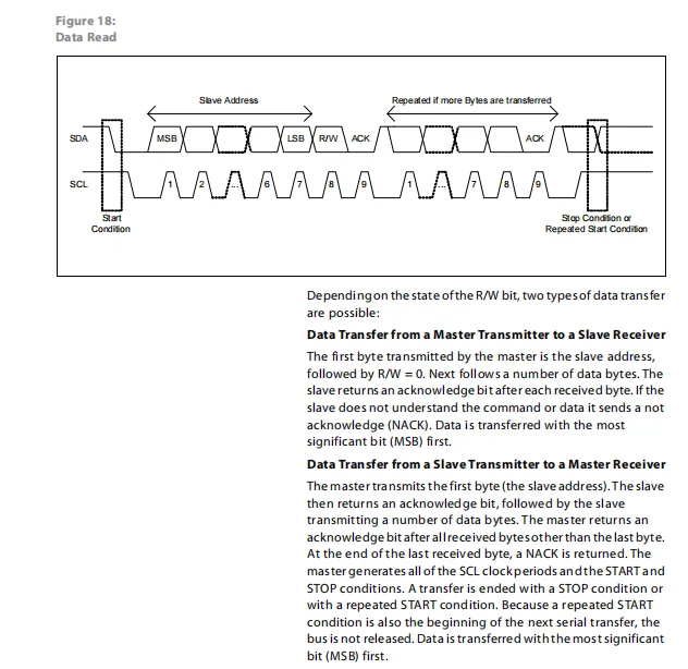
I²C data read/write timing: Communication starts with a start condition. The master first sends a 7-bit slave address plus a R/W bit (0 for write, 1 for read), and the slave responds with ACK; when the master sends data, the slave needs to respond with ACK byte by byte. When reading data, the master only responds with ACK to non-last bytes, and responds with NACK to the last byte. All data is transmitted with the most significant bit (MSB) first, and the communication ends with a stop or repeated start condition.
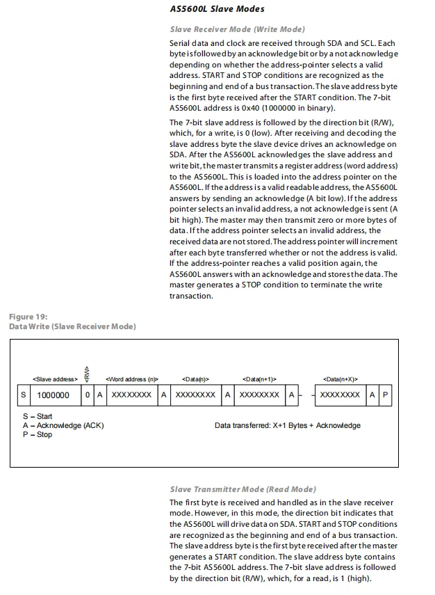
I²C slave mode: In write mode, the master sends the slave address (0x40, R/W = 0), register address and data; the slave responds with ACK for valid addresses and stores the data, with the address pointer automatically incrementing. In read mode, after the master sends the slave address (R/W = 1), the slave returns data according to the address pointer, and the master controls subsequent transmission via ACK. All communications are bounded by START / STOP conditions.
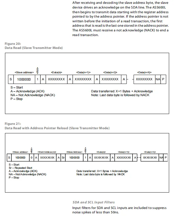
I²C read operation timing: In direct read mode, after the master sends the slave address (with the read bit set to 1), the slave continuously returns data according to the current address pointer, and the master only responds with NACK to terminate the communication after the last byte; in the read mode with address pointer reloading, the register address must first be sent via a write operation, then switched to read mode through a repeated start, and the slave returns data according to the reloaded address pointer. In both modes, the inputs of SDA / SCL have built-in filters, which can suppress noise spikes within 50ns.
2.8 PCB Routing Precautions
None.
III. Circuit Engineering
3.1 Circuit Source Engineering
To obtain the source code of the circuit, please follow the official account [Freak Embedded]
3.2 Module Usage Instructions
The schematic diagram of this module is shown below:
SCH_Schematic1_Magnetic Encoder Sensor Module Based on AS5600L_v1.0.0_2026-05-07.pdf 2.1 MB
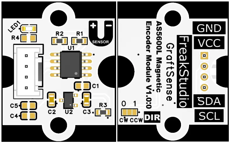
This module provides an IIC communication interface: it supports standard I2C communication rates, is compatible with 3.3V logic levels, and can stably transmit the 12-bit (4096-level) rotation angle digital signal acquired by AS5600L. Suitable for angle detection scenarios such as motor control, robot joints, and industrial automation, it provides the system with reliable and high-precision position data interaction capabilities.
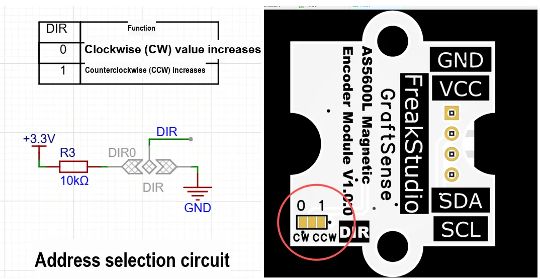
Here, we set an incremental counting direction by adjusting the back-side short-circuit points:
3.3 Application Experiment
Here, we use the GraftPort-RP2040 development board for testing, and the AS5600L-based magnetic encoder sensor module uses the I2C interface to communicate with the main controller.
Here, we first use the HY2.0-4P cable to connect the module to the GraftPort-RP2040 development board's I2C0 interface:
The module connections are shown in the following table:
Development Board Pins | Module Pins | Description |
Pin 4 |
|
|
Pin 5 |
|
|
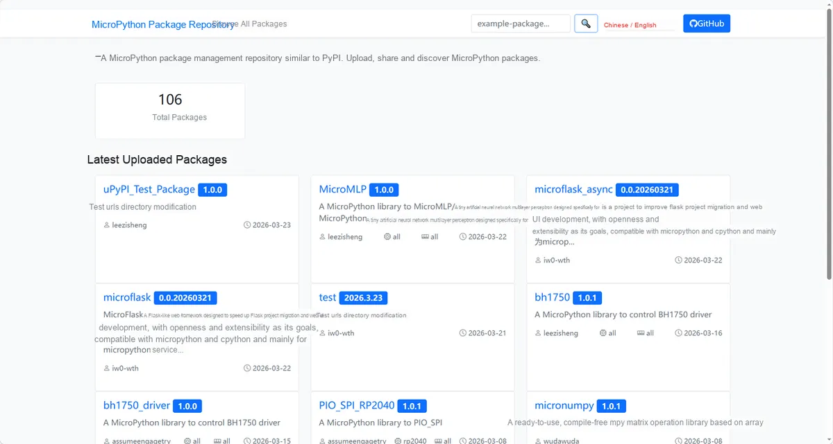
Here, we need to search for the relevant driver packages on uPyPI: https://upypi.net/zh/
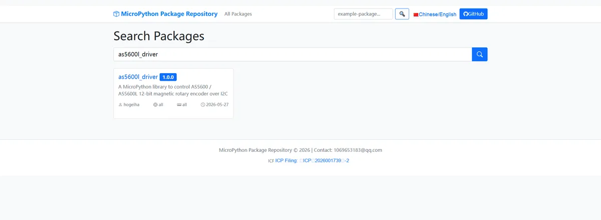
Enter as5600l_driver to search, and the following will be displayed:
Click to copy the local installation command:
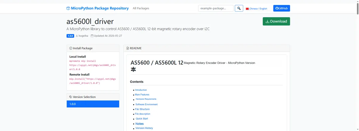
Import the module driver library code via the mip tool. Below are the usage commands for the mpremote tool:
mpremote mip install https://upypi.net/pkgs/as5600l_driver/1.0.0Import the AS5600L-based magnetic encoder sensor module - MicroPython driver code, then copy the following main.py code into our project:
# Python env   : MicroPython v1.23.0
# -*- coding: utf-8 -*-
# @Time    : 2025/05/15
# @Author  : hogeiha
# @File    : main.py
# @Description : Test the AS5600/AS5600L 12-bit magnetic rotary encoder driver class
# @License : MIT

__version__ = "1.0.0"
__author__ = "hogeiha"
__license__ = "MIT"
__platform__ = "MicroPython v1.23"

# ======================================== Import Modules =========================================

# Time-related interfaces
import time
# I2C bus
from machine import I2C, Pin
# AS5600 driver
from as5600 import AS5600

# ======================================== Global Variables ============================================

# I2C bus parameters
I2C_ID = 0
I2C_SCL_PIN = 5
I2C_SDA_PIN = 4
I2C_FREQ = 400000

# AS5600L default address (0x36 for the standard AS5600)
AS5600_ADDR = 0x40

# AS5600 has no WHO_AM_I register; use the STATUS register to verify the device responds
DEVICE_VERIFY_REG = 0x1B
# Only bit5/bit4/bit3 of the STATUS register are valid; the other bits are 0
DEVICE_VERIFY_MASK = 0xC7
DEVICE_VERIFY_EXPECTED = 0x00

# Main loop print interval (milliseconds)
PRINT_INTERVAL_MS = 1000
last_print_time = time.ticks_ms()

# ======================================== Functions ============================================

def print_realtime_angle():
    """Read the real-time angle at high frequency (commented out by default; can be called manually in the REPL)"""
    # Read raw and mapped angles
    raw = sensor.rawangle()
    mapped = sensor.angle()
    # Convert 12-bit resolution to degrees
    print("Raw: %d  Angle: %d  (%.2f deg)" % (raw, mapped, mapped * 360.0 / 4096.0))


def print_status():
    """Print magnet status, AGC and magnetic field strength"""
    # Magnet detection tri-state
    md = sensor.md()
    ml = sensor.ml()
    mh = sensor.mh()
    # Automatic gain and magnetic field strength
    agc = sensor.agc()
    mag = sensor.magnitude()
    print("Magnet: detected=%d weak=%d strong=%d  AGC=%d  Magnitude=%d"
          % (md, ml, mh, agc, mag))


def print_config():
    """Print the current configuration registers (bit fields of ZMCO/ZPOS/MPOS/MANG/CONF)"""
    # Burn count
    zmco = sensor.zmco()
    # Angle mapping related
    zpos = sensor.zpos()
    mpos = sensor.mpos()
    mang = sensor.mang()
    # Split CONF register into bit fields
    pm = sensor.pm()
    hyst = sensor.hyst()
    outs = sensor.outs()
    pwmf = sensor.pwmf()
    sf = sensor.sf()
    fth = sensor.fth()
    wd = sensor.watchdog()
    print("ZMCO=%d ZPOS=%d MPOS=%d MANG=%d" % (zmco, zpos, mpos, mang))
    print("CONF: PM=%d HYST=%d OUTS=%d PWMF=%d SF=%d FTH=%d WD=%d"
          % (pm, hyst, outs, pwmf, sf, fth, wd))


def test_boundary_write():
    """Boundary parameter scenario: write 0 and 4095 to ZPOS (12-bit minimum/maximum)"""
    # Write minimum value
    sensor.zpos(0)
    v0 = sensor.zpos()
    # Write maximum value
    sensor.zpos(4095)
    v1 = sensor.zpos()
    print("Boundary ZPOS write: 0 -> %d, 4095 -> %d" % (v0, v1))


def test_invalid_args():
    """Invalid parameter scenario: verify that illegal parameters correctly raise ValueError"""
    # Invalid register address
    try:
        sensor.readwrite(0x100, 7, 0)
    except ValueError as e:
        print("Caught register out-of-range: %s" % e)
    # Invalid bit field
    try:
        sensor.readwrite(0x07, 3, 5)
    except ValueError as e:
        print("Caught invalid bitfield: %s" % e)
    # Write value exceeding bit field range
    try:
        sensor.zpos(0x10000)
    except ValueError as e:
        print("Caught value out-of-range: %s" % e)
    # Error type
    try:
        sensor.zpos("bad")
    except ValueError as e:
        print("Caught wrong type: %s" % e)


def burn_angle_once():
    """Burn angles (ZPOS/MPOS) into OTP, irreversible, triggered manually in the REPL only"""
    sensor.burn_angle()
    print("burn_angle issued")


def burn_setting_once():
    """Burn settings (MANG/CONF) into OTP, irreversible, triggered manually in the REPL only"""
    sensor.burn_setting()
    print("burn_setting issued")

# ======================================== Custom Classes ============================================

# ======================================== Initialization ==========================================

time.sleep(3)
print("FreakStudio: AS5600/AS5600L magnetic encoder driver test")

# Initialize I2C bus
i2c = I2C(I2C_ID, scl=Pin(I2C_SCL_PIN), sda=Pin(I2C_SDA_PIN), freq=I2C_FREQ)

# Scan the I2C bus
devices = i2c.scan()
if not devices:
    raise RuntimeError("No I2C device found")
print("I2C scan result: %s" % [hex(d) for d in devices])

# Verify the target address is online
if AS5600_ADDR not in devices:
    raise RuntimeError("Device not found at expected address 0x%02X" % AS5600_ADDR)
print("Target device 0x%02X present on bus" % AS5600_ADDR)

# Device response verification (AS5600 has no WHO_AM_I; read the STATUS register instead and compare the reserved bits using a mask)
_probe = i2c.readfrom_mem(AS5600_ADDR, DEVICE_VERIFY_REG, 1)[0]
if (_probe & ~DEVICE_VERIFY_MASK) == DEVICE_VERIFY_EXPECTED:
    print("Device found (STATUS=0x%02X)" % _probe)
else:
    print("Device not found (STATUS=0x%02X, unexpected reserved bits)" % _probe)

# Create driver instance
sensor = AS5600(i2c, device=AS5600_ADDR, debug=False)

# ========================================  Main Program  ===========================================

try:
    # Print configuration and status once at startup
    print_config()
    print_status()
    while True:
        current_time = time.ticks_ms()
        if time.ticks_diff(current_time, last_print_time) >= PRINT_INTERVAL_MS:
            # Low-frequency core acquisition: angle + status
            raw = sensor.rawangle()
            mapped = sensor.angle()
            md = sensor.md()
            print("Angle raw=%d mapped=%d (%.2f deg)  magnet=%d"
                  % (raw, mapped, mapped * 360.0 / 4096.0, md))
            last_print_time = current_time
        # print_realtime_angle()   # High-frequency angle reading, commented out by default, call manually in the REPL
        # print_status()           # Status/AGC/magnitude, commented out by default, call manually in the REPL
        # print_config()           # Configuration readback, commented out by default, call manually in the REPL
        # test_boundary_write()    # Boundary parameters, commented out by default, call manually in the REPL
        # test_invalid_args()      # Invalid parameters, commented out by default, call manually in the REPL
        # burn_angle_once()        # OTP burning is irreversible, triggered manually in the REPL only
        # burn_setting_once()      # OTP burning is irreversible, triggered manually in the REPL only
        time.sleep_ms(10)

except KeyboardInterrupt:
    print("Program interrupted by user")
except OSError as e:
    print("Hardware communication error: %s" % str(e))
except Exception as e:
    print("Unknown error: %s" % str(e))
finally:
    print("Cleaning up resources...")
    try:
        sensor.deinit()
    except Exception:
        pass
    del sensor
    print("Program exited")
Burn the code, open the terminal, and the output is as follows:
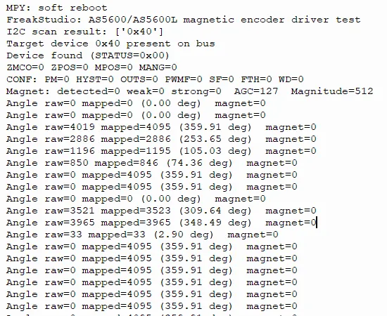
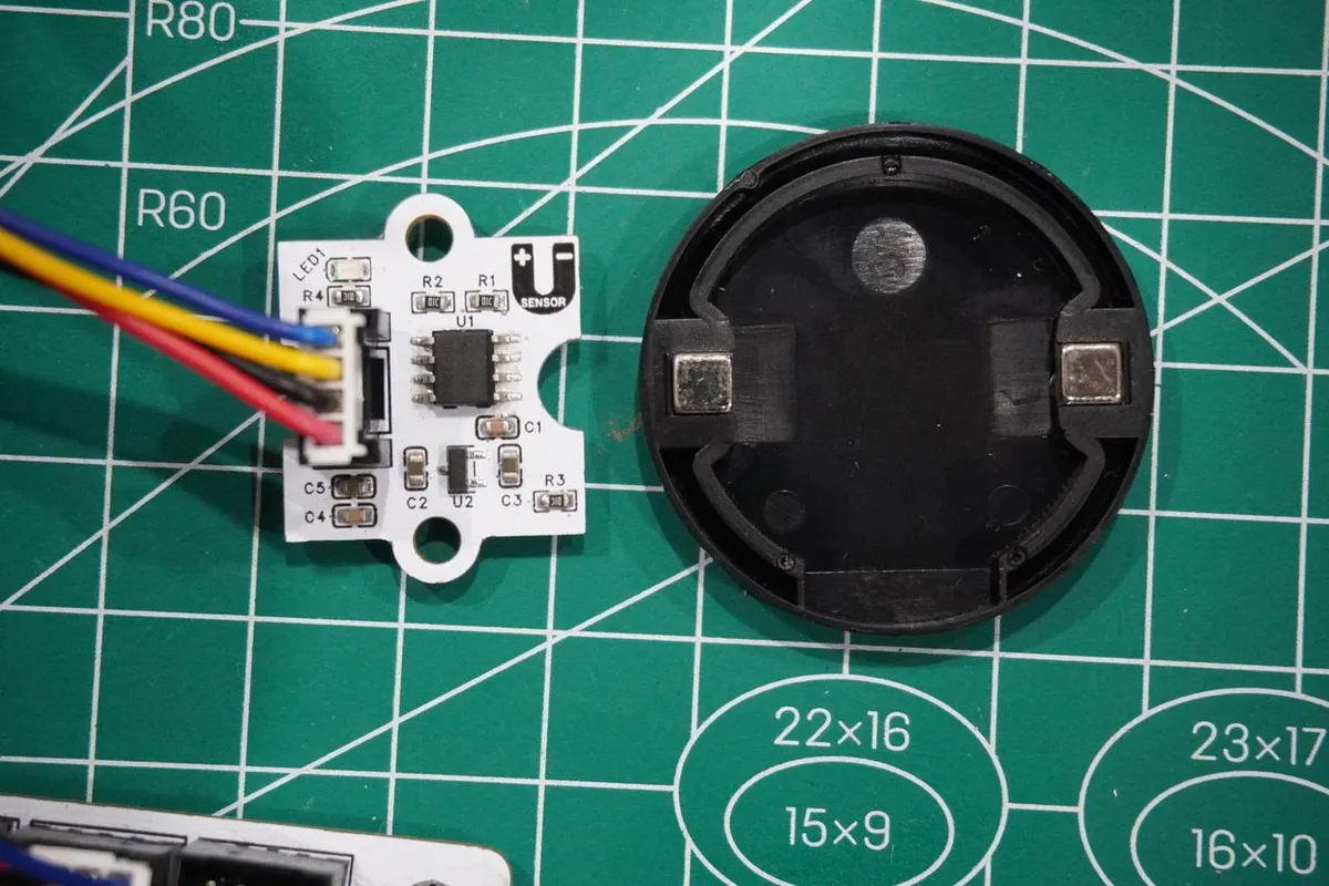
It can be seen that when the magnet approaches, the AS5600 successfully detects the magnetic field and outputs continuous and smooth angle data; after the magnet is removed, the sensor returns to the no-magnetic-field state, and the angle data jumps between 0° and 359.91°.
IV. Drivers
as5600l_driver-1.0.0.zip 13 KB
5. BOM & Recommended Alternative Parts
None.
VI. Revision History
Document Version | Date Modified | Modifier | Modify Content |
v1.0 | 2026-05-07 | Ling Gaoxing | Initialize the document |
v1.1 | 2026-06-06 | Xin Ruili | Create an open version of the document based on the internal document version v1.0. |
7. Relevant Materials
7.1 Chip Datasheet
AS5600L.pdf 1.1 MB
7.2 Unique Icons for PCB Silk Screen