Contents
- I. Module Introduction
- II. Introduction to Major Chips
- 2.1 Chip Overview
- 2.2 Pin Definition
- 2.3 Functional Block Diagram
- 2.4 Performance Parameters
- 2.5 Reference Circuit
- 2.6 Chip Configuration
- 2.7 Communication Interfaces and Related Protocols
- 2.8 PCB Routing Precautions
- III. Circuit Engineering
- 3.1 Circuit Source Engineering
- 3.2 Module Usage Instructions
- 3.3 Application Experiment
- IV. Drivers
- 5. BOM & Recommended Alternative Parts
- VI. Revision History
- VII. Relevant Materials
- 7.1 Chip Datasheet
- 7.2 Unique Icons for PCB Silkscreen
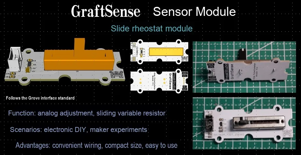
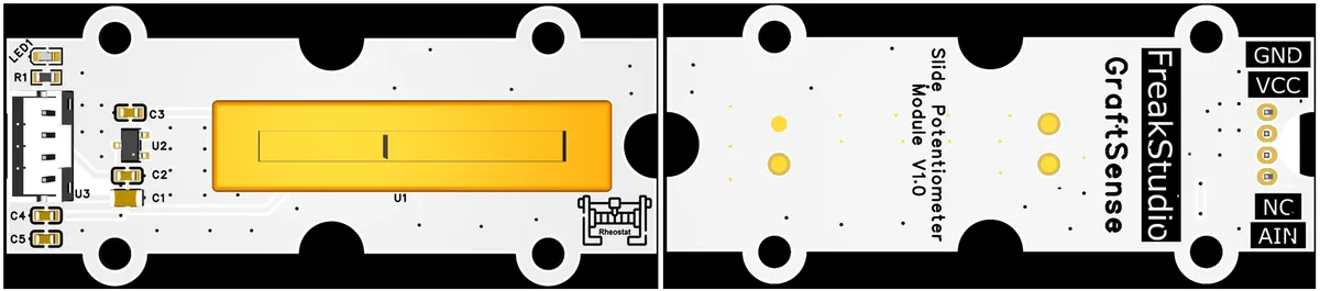
I. Module Introduction
Slide Potentiometer Module is an analog adjustment module based on a 35mm linear slide potentiometer (with a maximum resistance of 10K). It integrates a DC-DC 5V to 3.3V conversion circuit, LED indicator, filtering circuit and standard interface, which can convert the linear displacement of the slider into an analog voltage signal ranging from 0 to VCC (compatible with 3.3V/5V). This module is convenient to connect to the ADC pins of main control devices such as Arduino and Raspberry Pi, and is suitable for maker project scenarios requiring analog interaction such as volume adjustment, brightness control and position sensing.
II. Introduction to Major Chips
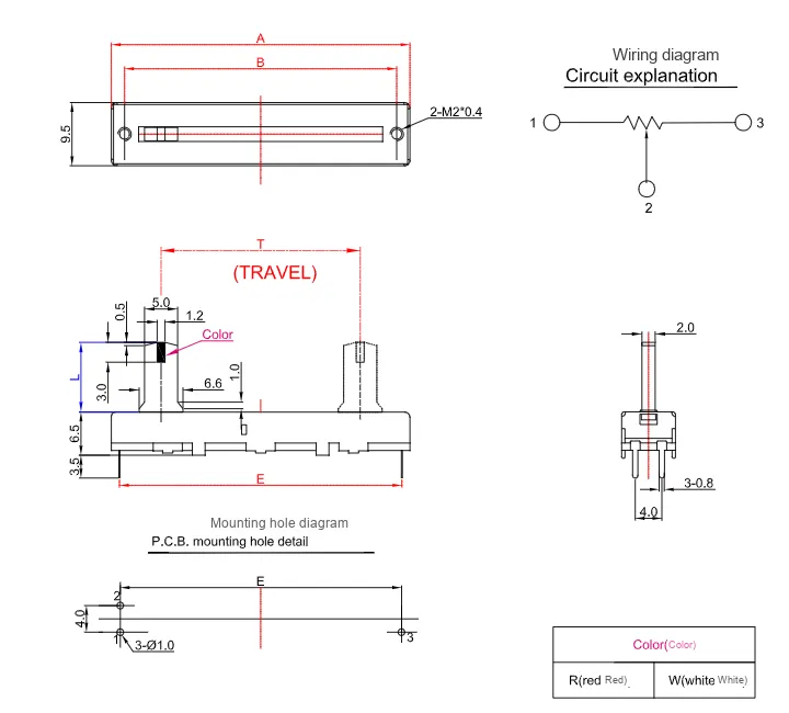
This module mainly relies on a 35mm linear potentiometer (with a maximum resistance of 10K) to achieve signal variation.
2.1 Chip Overview
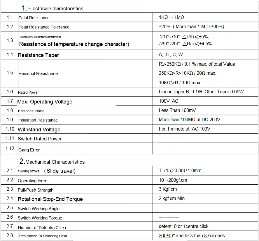
This 35mm slide potentiometer features a maximum resistance of 10K, a total resistance tolerance of ±20%, and a linear resistance variation characteristic; its rated power for linear Type B reaches 0.1W. Mechanically, it boasts precise parameters including sliding travel, is compatible with metal or insulated push handles, operates within a temperature range of -10℃ to + 70℃, and has a rotation lifespan of no less than 10,000 cycles, making it suitable for scenarios such as voltage regulation of electronic equipment and position sensing.
2.2 Pin Definition
2.3 Functional Block Diagram
None.
2.4 Performance Parameters
2.5 Reference Circuit
None
2.6 Chip Configuration
None.
2.7 Communication Interfaces and Related Protocols
None.
2.8 PCB Routing Precautions
None.
III. Circuit Engineering
3.1 Circuit Source Engineering
To obtain the source project of the circuit, please follow the official account [Freak Embedded]
3.2 Module Usage Instructions
The schematic diagram of this module is shown below:
SCH_Slide Potentiometer Module_v1.0_2025-09-24..pdf 2.1 MB
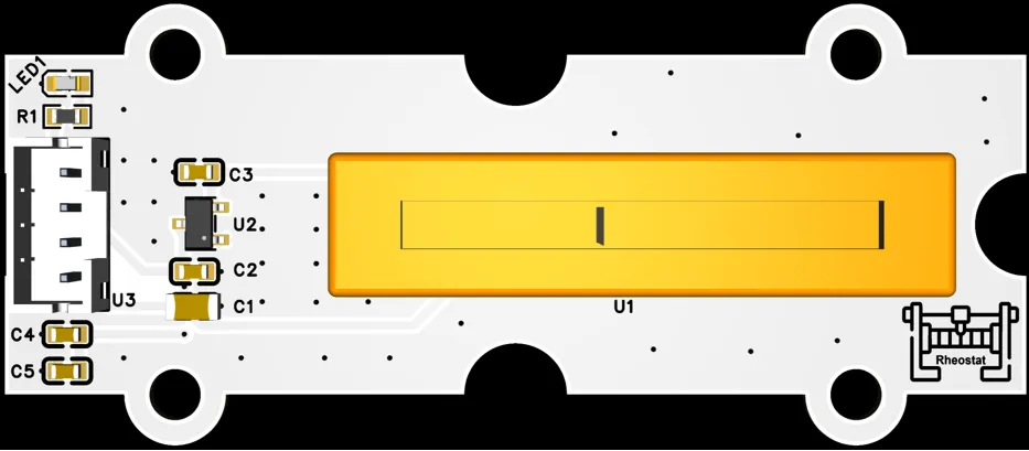
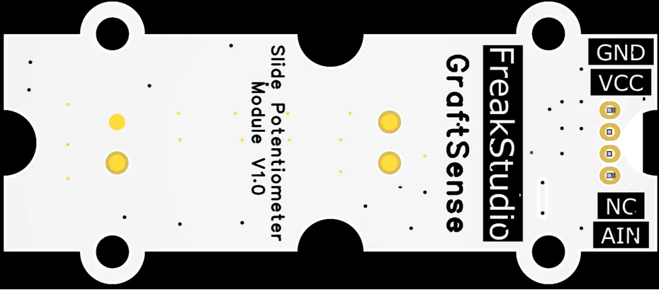
This module uses analog output AIN: the analog output pin AIN of this module can convert the resistance change of the sliding potentiometer into an analog voltage signal, with a maximum output voltage of 3.3V, which can vary linearly within the range of 0 to 3.3V.
3.3 Application Experiment
Here, we use the GraftPort-RP2040 development board for testing, and connect the sliding rheostat module via its AIN interface to communicate with the main controller.
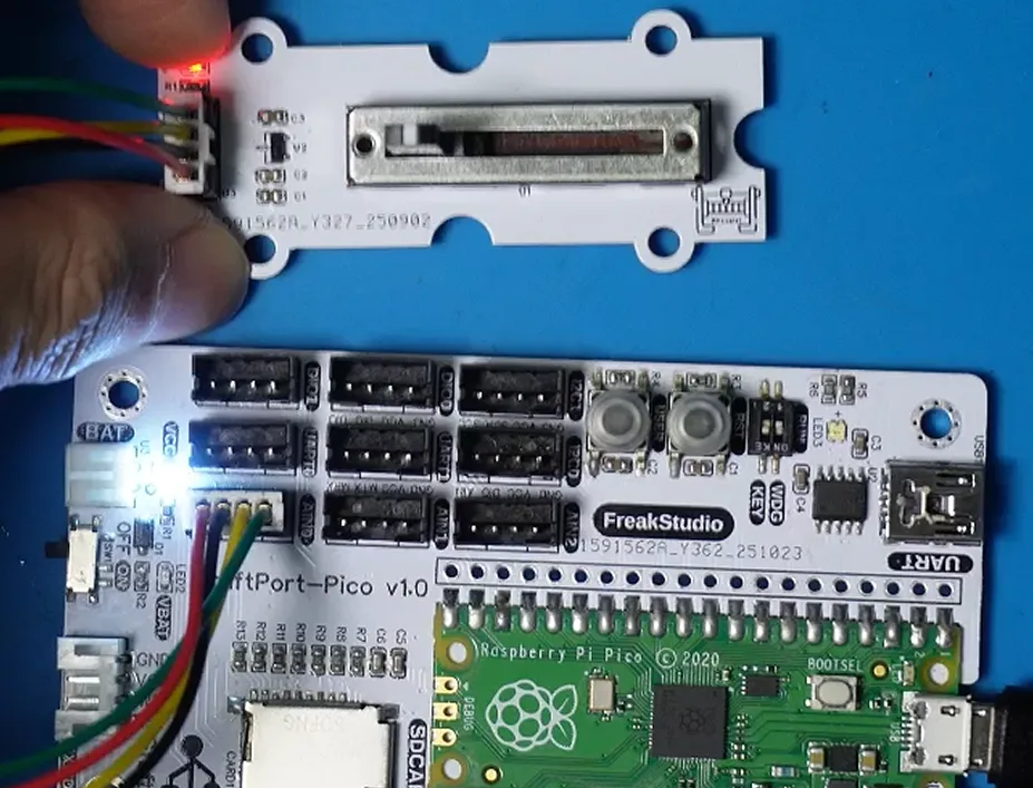
Here, we first use the HY2.0-4P cable to connect the module to the GraftPort-RP2040 development board's AIN0 interface:
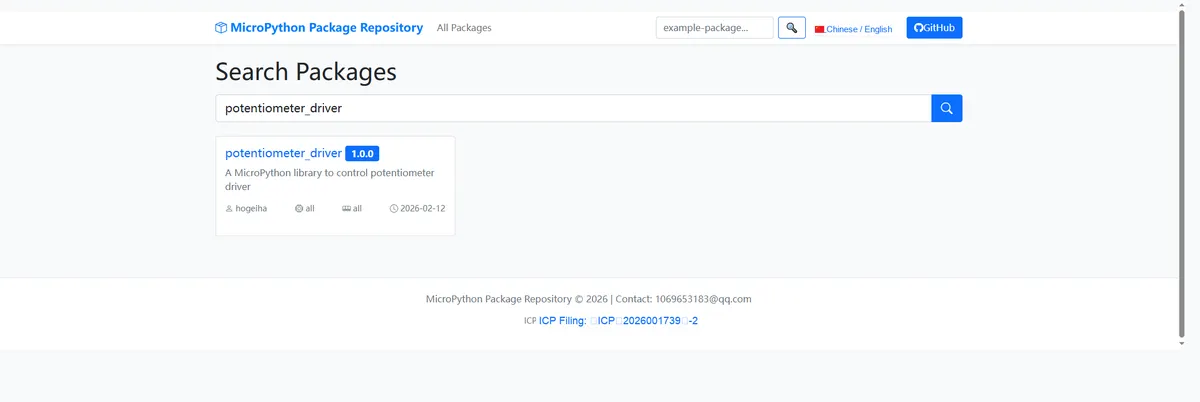
Here, we need to search for the relevant driver packages on uPyPI: https://upypi.net/zh/
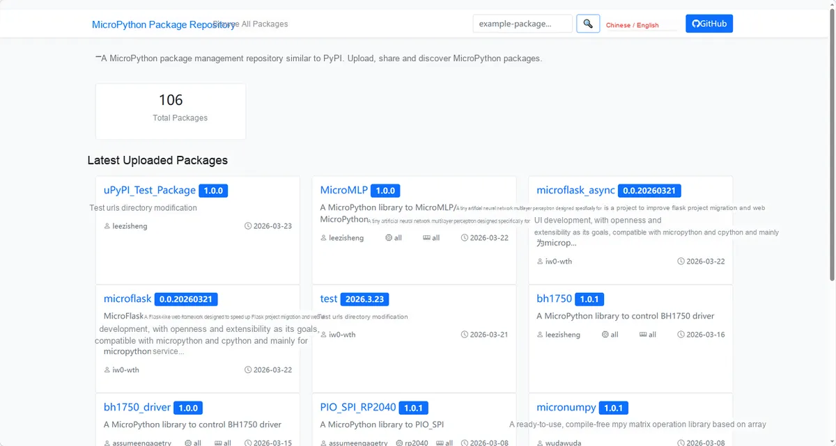
Enter potentiometer_driver to search, and the following will be displayed:
Click to copy the local installation command:
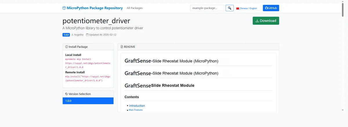
Here, we can import the module driver library code via the mip tool. Below are the usage commands for the mpremote tool:
mpremote mip install github:FreakStudioCN/GraftSense-Drivers-MicroPython/input/potentiometer_driverThe module connections are shown in the following table:
Development Board Pins | Module Pins | Description |
Pin 26 |
| The input interface for the voltage signal of the sliding rheostat on the MCU |
Pin 19 |
| - |
After importing the sliding rheostat module - MicroPython driver code, copy the following main.py code into our project:
# Python env   : MicroPython v1.23.0
# -*- coding: utf-8 -*-
# @Time    : 2025/8/28 3:19 PM
# @Author  : 缪贵成
# @File    : main.py
# @Description : Sliding rheostat test file

# ======================================== Import Modules =========================================

import time
from machine import ADC
from potentiometer import Potentiometer

# ======================================== Global Variables ============================================

# ======================================== Functions ============================================

# ======================================== Custom Classes ============================================


# ======================================== Initialization configuration ===========================================

time.sleep(3)
print("FreakStudio:Sliding rheostat module testing")
# Slide rheostat voltage output is connected to ADC0
adc = ADC(26)
pot = Potentiometer(adc)

# ========================================  Main Program  ============================================

interval = 0.5
try:
    while True:
        # Get the current status dictionary
        state = pot.get_state()
        # Print the current status
        print(f"State: raw={state['raw']}, voltage={state['voltage']:.3f} V, ratio={state['ratio']:.3f}")
        # Wait for the next read
        time.sleep(interval)

except KeyboardInterrupt:
    print("\nTest terminated by user.")
Burn the code, open a terminal, and use the mpremote tool to connect to the main controller; the output is as follows:
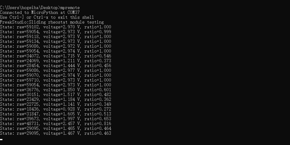
It can be seen that as we adjust the sliding rheostat, the voltage value and the sliding proportion value displayed on the terminal will change accordingly:
IV. Drivers
5. BOM & Recommended Alternative Parts
None.
VI. Revision History
Document Version | Date of Revision | Modifier | Modified Content |
v1.0 | 2025-08-31 | Hou Junhan, Ling Gaoxing | Initialize the document |
v1.1 | 2025-09-24 | Li Zisheng | The BOM sheet has not been finally checked, the driver has not been re-verified, and the 3.3 application experiment Not yet specified. |
v1.2 | 2025-12-29 | Li Zisheng | Added application experiments and production files |
v1.3 | 2025-12-31 | Xin Ruili | Create an open version of the document based on the internal document version v1.2. |
v1.4 | 2026-03-29 | Xin Ruili | Modified the application experiment section. |
VII. Relevant Materials
7.1 Chip Datasheet
Single-Gang Linear Slide Potentiometer Datasheet (Multiple Specifications, Worth a Look).pdf 1.0 MB
7.2 Unique Icons for PCB Silkscreen