Contents
- I. Module Introduction
- II. Introduction to Major Chips
- 2.1 Chip Overview
- 2.2 Pin Definition
- 2.3 Functional Block Diagram
- 2.4 Performance Parameters
- 2.5 Reference Circuit
- 2.6 Chip Configuration
- 2.7 Communication Interfaces and Related Protocols
- 2.8 PCB Routing Precautions
- III. Circuit Engineering
- 3.1 Circuit Source Engineering
- 3.2 Module Usage Instructions
- 3.3 Application Experiment
- IV. Drivers
- 5. BOM & Recommended Alternative Parts
- VI. Revision History
- VII. Relevant Materials
- 7.1 Chip Datasheet
- 7.2 Unique Icons for PCB Silkscreen
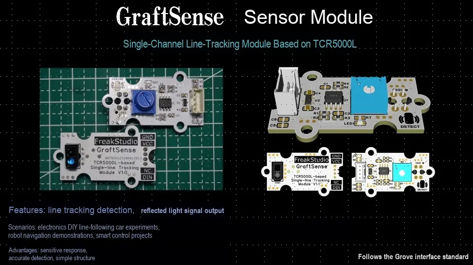
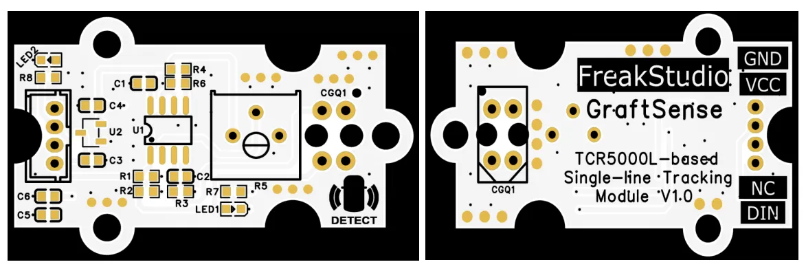
I. Module Introduction
TCR5000L-based Single-channel Tracking Module. This module takes TCRT5000L infrared sensor and LM393DT comparator as its core. The tracking sensitivity can be adjusted via a 10kΩ potentiometer. By utilizing the difference in infrared reflection intensity (strong reflection from white background, weak reflection from black track line), it changes the conduction level of the phototransistor, and outputs a level signal through the comparator to realize track recognition. This module is suitable for scenarios such as intelligent car tracking, and provides a simple and reliable hardware solution for automatic track tracking applications.
II. Introduction to Major Chips
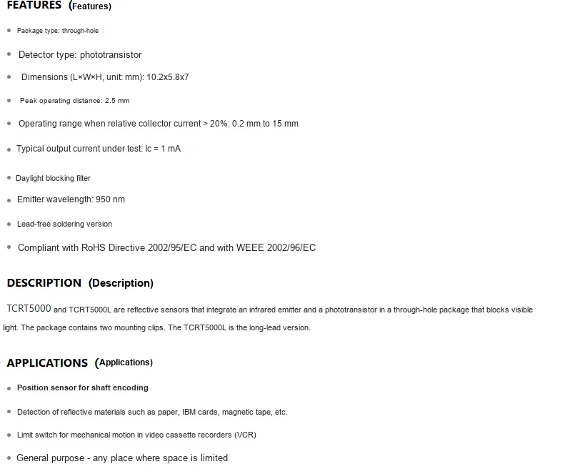
TCRT5000L is a reflective optical sensor with a built-in infrared emitter and phototransistor. It emits infrared light at a wavelength of 950nm and is equipped with a daylight blocking filter to mitigate ambient light interference. It features a peak operating distance of 2.5mm, an effective Scope of Work of 0.2 - 15mm, a typical output current of 1mA under test conditions, and is compatible with 3.3V - 5V power supply. Compliant with environmental protection standards such as RoHS, this compact component (10.2mm×5.8mm×7mm) is suitable for integration in space-constrained scenarios, and is commonly used in applications including shaft encoder positioning, detection of reflective materials such as paper, and mechanical motion limit switches.
2.1 Chip Overview
2.2 Pin Definition
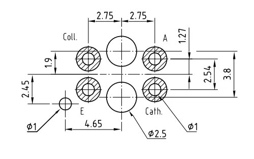
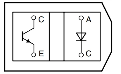
Pin | Description |
Coll | The collector of the phototransistor serves as the signal output terminal, which is used to output electrical signals that reflect the infrared reflection status. |
E | The emitter of the phototransistor. |
A | The positive electrode of the infrared emitting diode. |
Cath | The negative electrode of the infrared emitting diode. |
2.3 Functional Block Diagram
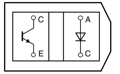
TCRT5000L The functional block diagram of TCRT5000L is shown in the figure above. TCRT5000L is a reflective photoelectric sensor that integrates an infrared emitting diode and a phototransistor into a single unit.
When an infrared emitting diode is in operation, it emits infrared rays of a specific wavelength outwards. When the infrared rays hit a reflective object, the light is reflected back and strikes the photosensitive area of the phototransistor. At this point, the phototransistor conducts between its collector (C) and emitter (E), generating a current; if the infrared rays are not reflected (for example, when they hit a black non-reflective object), the phototransistor remains in an off state. By detecting the level change at the collector, the reflection status of the object ahead can be determined, thus enabling functions such as line tracking, obstacle avoidance, and distance detection.
2.4 Performance Parameters
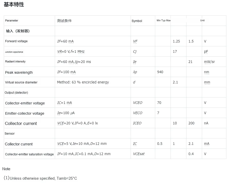
The basic characteristics of TCRT5000L (at 25°C) are shown as follows:
- Transmitter:
- Forward voltage 1.25~1.5V (
IF= 60mA); - Junction Capacitance 17pF (
VR=0V,f=1MHz); - Maximum radiation intensity 21mW/sr (
IF= 60mA,tp= 20ms); - Peak wavelength 940nm (
IF= 100mA); - Virtual source diameter: 2.1 mm.
- Forward voltage 1.25~1.5V (
- Detector:
- Collector-Emitter Voltage 70 V (
I<sub>C</sub>= 1 mA); - Emitter-collector voltage 7 V (
I_E= 100 μA); - Collector leakage current: 10~200 nA (
VCE= 20 V,IF= 0 A,E= 0 lx).
- Collector-Emitter Voltage 70 V (
- Sensor:
- Collector current 0.5~2.1mA (
VCE= 5V,IE= 10mA,D= 12mm); - Maximum Collector-Emitter Saturation Voltage: 0.4 V (
IF= 10 mA,IC= 0.1 mA,D= 12 mm).
- Collector current 0.5~2.1mA (
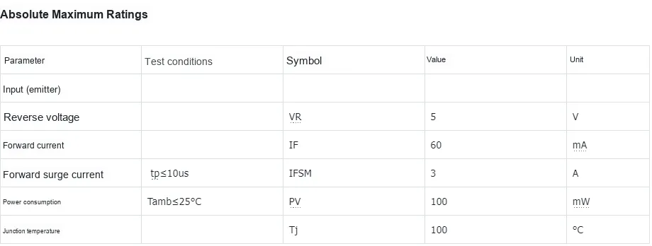
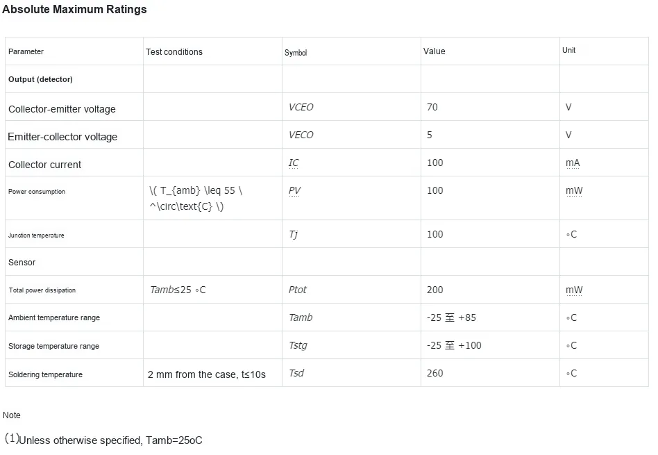
The maximum ratings (at 25°C) of TCRT5000L are shown as follows:
- Probe:
- Maximum Collector-Emitter Voltage 70V, Maximum Emitter-Collector Voltage
5V; - Maximum collector current 100mA;
- Maximum Power Consumption: 100 mW (
Tamb≤ 55℃); - Junction temperature 100℃.
- Total power consumption of the sensor: 200 mW (
Tamb≤ 25℃); - Ambient temperature: -25 to + 85℃, Storage temperature: -25 to + 100℃;
- Soldering temperature: 260℃(2 mm from the housing,
t≤ 10 s).
- Maximum Collector-Emitter Voltage 70V, Maximum Emitter-Collector Voltage
- Transmitter:
- Maximum reverse voltage: 5V;
- Forward Current 60mA;
- Peak Forward Surge Current: 3 A (
tₚ≤ 10 µs); - Power consumption: 100mW (
Tamb≤ 25℃); - Junction temperature 100℃.
2.5 Reference Circuit
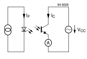
This diagram is TCR5000L a reference application circuit for an optocoupler, which consists of two parts: the transmitter and the receiver.
On the left is the transmitting end, where the power supply drives the light-emitting diode to generate a current IF and make it emit an optical signal;
The right side is the receiving end. After the phototransistor of TCR5000L receives the optical signal, it generates a collector current IC under the power supply of VCC. The ammeter A is used to detect the magnitude of IC, so as to reflect the coupling transmission effect of the optical signal from the transmitting end to the receiving end (the correlation between IC and IF is determined by the optical coupling efficiency).
2.6 Chip Configuration
TCRT5000L is a sensor and does not require additional configuration during use.
2.7 Communication Interfaces and Related Protocols
TCRT5000L outputs analog signals and is not equipped with communication interfaces or related protocols.
2.8 PCB Routing Precautions
None.
III. Circuit Engineering
3.1 Circuit Source Engineering
To obtain the source project of the circuit, please follow the official account [Freak Embedded]
3.2 Module Usage Instructions
SCH_Schematic1_Single-Channel Line Tracking Module Based on TCR5000L_v1.0_2025-11-12.pdf 1.9 MB
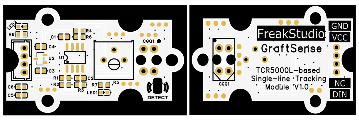
This module is equipped with a digital output interface DOUT: Specifically, R5 is a 10kΩ potentiometer used to adjust the tracking sensitivity; the interface outputs a high level by default. When the module detects a black track line, the infrared light reflected by the black background is weak, which reduces the conduction level of the phototransistor. After the corresponding electrical signal is processed by the LM393 comparator, DIN interface will switch from high level to low level, and output a binary signal (high/low) corresponding to the track state, which is suitable for automatic track tracking scenarios such as intelligent car tracking.
3.3 Application Experiment
Here, we use the GraftPort-RP2040 development board for testing, and connect the single-channel tracking module based on TCR5000L to communicate with the main controller via the DIO interface.
Here, we first use the HY2.0-4P cable to connect the module to the GraftPort-RP2040 development board's DIO0 interface:
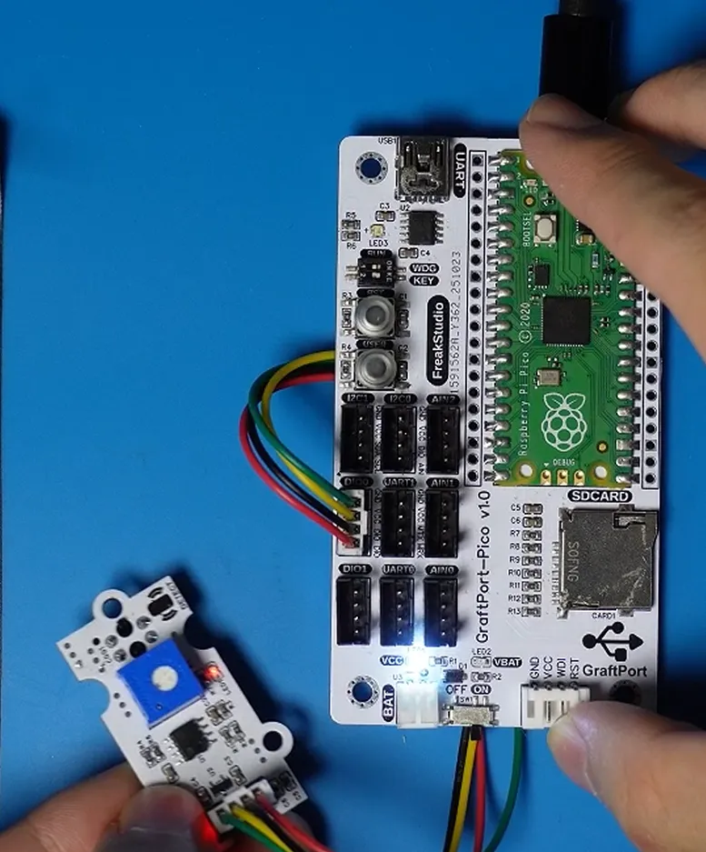
The module connections are shown in the following table:
Development Board Pins | Module Pins | Description |
Pin 6 |
| Tracking probe digital signal input pin |
Pin 7 |
| - |
Before using the single-line tracking module based on TCR5000L, calibration is required first:
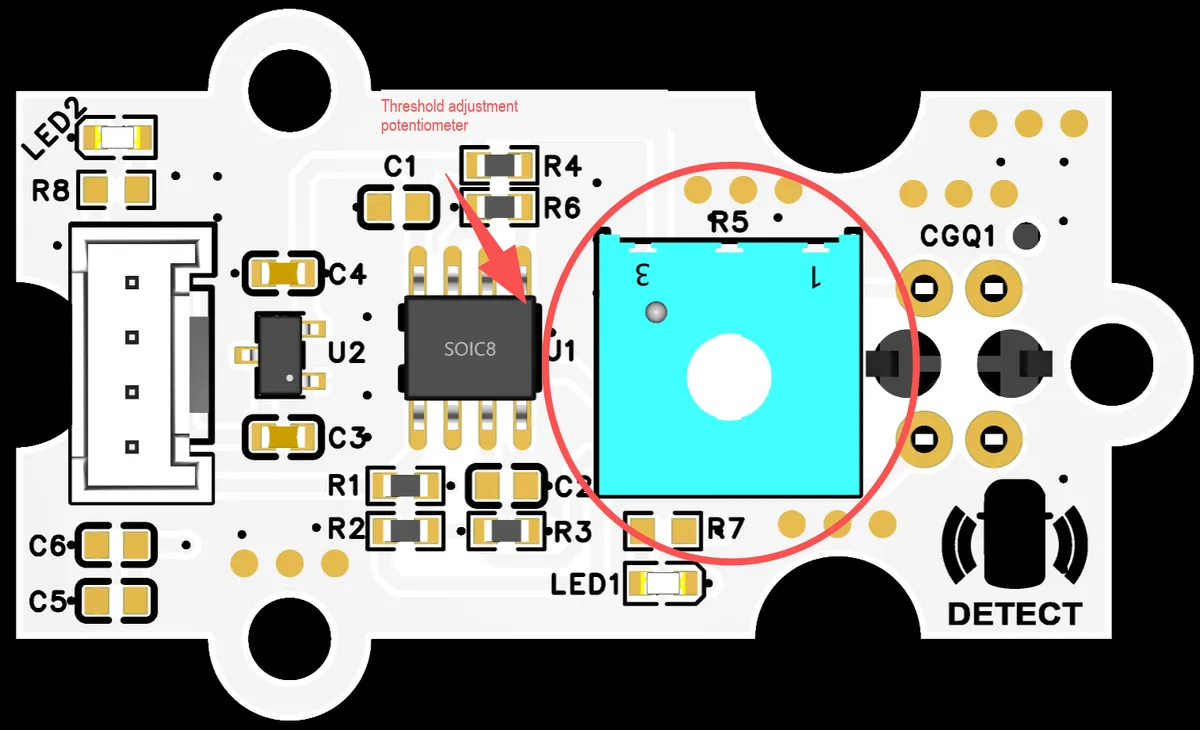
- White background calibration: Aim the probe at a pure white background and observe
DOindicator and output; adjust theR5potentiometer to turn on the indicator; - Black line calibration: Align the probe with the center of the black line, then keep adjusting the potentiometer until the indicator light goes out;
- Boundary verification: Slowly move the module; it should switch rapidly at the black-and-white boundary without prolonged jitter. If the switching is blurry, fine-tune the potentiometer until the boundary is clear.
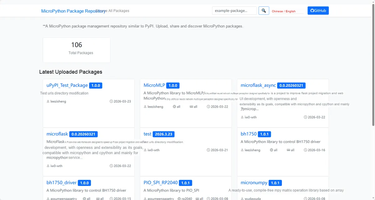
Here, we need to search for the relevant driver packages on uPyPI: https://upypi.net/zh/
Enter tcr5000_driver to search, and the following will be displayed:
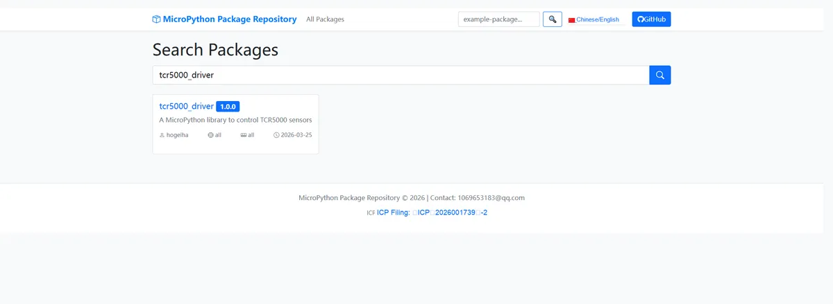
Click to copy the local installation command:
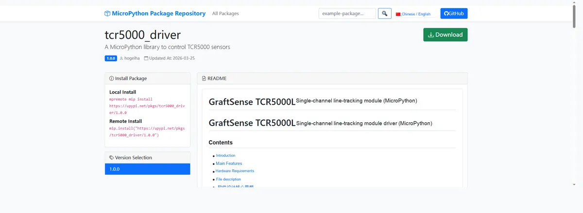
Here, we can use the mip tool to import module driver library code. The following are the usage commands for the mpremote tool:
mpremote mip install github:FreakStudioCN/GraftSense-Drivers-MicroPython/sensors/tcr5000_driverAfter importing the driver for TCR5000L single-channel tracking module - MicroPython driver code, copy the following main.py code into our project:
# MicroPython v1.23.0
# -*- coding: utf-8 -*-
# @Time    : 2025/9/4 AM 9:44
# @Author  : 缪贵成
# @File    : main.py
# @Description : Single-channel line-tracking module driver test file

# ======================================== Import Modules =========================================

import time
from tcr5000 import TCR5000

# ======================================== Global Variables ============================================

# ======================================== Functions ============================================

def on_change(value: int) -> None:
    """
    Callback for TCR5000 level changes, triggered when the sensor level changes.

    Args:
        value (int): current level, 0=black line, 1=white background.

    Notes:
        The callback is scheduled to run in the main loop via micropython.schedule, avoiding time-consuming operations inside the ISR.
        The user can handle sensor state changes in the callback, for example printing or controlling a motor.

    ==========================================

    TCR5000 level change callback, triggered on sensor level change.

    Args:
        value (int): Current pin value, 0=black line, 1=white background.

    Notes:
        Callback is scheduled via micropython.schedule to main loop context, avoiding ISR execution.
        User can handle sensor state changes here, e.g., print or motor control.
    """
    print("Callback triggered, value =", value)

# ======================================== Custom Classes ============================================

# ======================================== Initialization ==========================================

time.sleep(3)
print("FreakStudio:Single-channel tracking module test")
# Initialize TCR5000 sensor
sensor = TCR5000(pin=6)
# Register callback function
sensor.set_callback(on_change)

# ========================================  Main Program  ===========================================

try:
    while True:
        val = sensor.read()
        print("Current value:", val)
        time.sleep(1)

except KeyboardInterrupt:
    sensor.deinit()
    print("Program interrupted, resources released.")
Burn the code, open the terminal, and use the mpremote tool to connect to the main controller. The output is as follows:
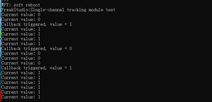
It can be seen that when the line-tracking module detects the black line, it triggers the callback function, and the onboard status indicator LED1 lights up:
IV. Drivers
tcr5000_driver.zip 9 KB
5. BOM & Recommended Alternative Parts
None.
VI. Revision History
Document Version | Date of Modification | Modifier | Modified Content |
v1.0 | 2025-11-12 | Ling Gaoxing | Initialize the document |
v1.1 | 2025-12-29 | Li Zisheng | Added application experiments and production files |
v1.2 | 2025-12-31 | Xin Ruili | Create an open version of the document based on the internal document version v1.1. |
v1.3 | 2026-03-29 | Xin Ruili | Modified the application experiment section |
VII. Relevant Materials
7.1 Chip Datasheet
TCRT5000L Manual.pdf 306 KB
7.2 Unique Icons for PCB Silkscreen