Contents
- I. Module Introduction
- II. Introduction to Major Chips
- 2.1 Chip Overview
- 2.2 Pin Definition
- 2.3 Functional Block Diagram
- 2.4 Performance Parameters
- 2.5 Reference Circuit
- 2.6 Chip Configuration
- 2.7 Communication Interfaces and Related Protocols
- 2.8 PCB Routing Precautions
- III. Circuit Engineering
- 3.1 Circuit Source Engineering
- 3.2 Module Usage Instructions
- 3.3 Application Experiment
- 4. Drivers
- 5. BOM & Recommended Alternative Parts
- VI. Revision History
- VII. Relevant Materials
- 7.1 Chip Datasheet
- 7.2 PCB Silkscreen Specific Icons
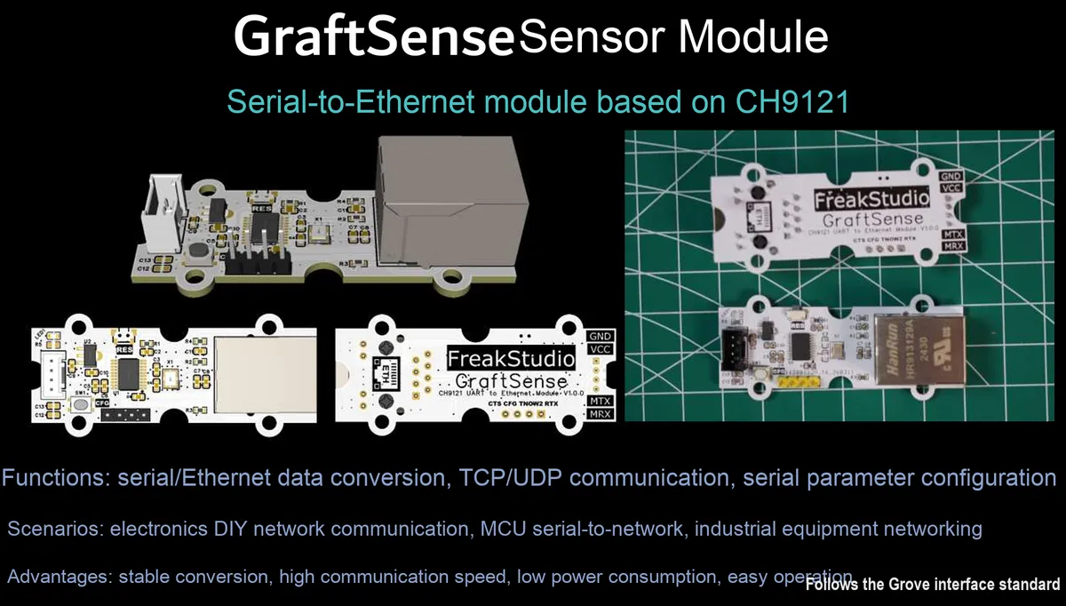
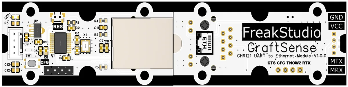
I. Module Introduction
CH9121-based Serial Port to Ethernet Module, which adopts the CH9121 chip solution, supports bidirectional transparent data transmission between the UART serial port and Ethernet, features CFG configuration pins and CTS flow control function, is equipped with a network transformer and crystal oscillator circuit, powered by 3.3V with built-in power filtering and indicator circuits, and enables quick access of serial port devices to Ethernet. It is applicable to networked application scenarios such as industrial control, IoT gateways, and remote Data Acquisition.
II. Introduction to Major Chips
CH9121 is a UART-to-Ethernet chip integrated with the TCP / IP protocol stack. It supports bidirectional data transparent transmission between UART and Ethernet, allows working mode configuration via external pins, and enables serial port devices to quickly access Ethernet.
2.1 Chip Overview
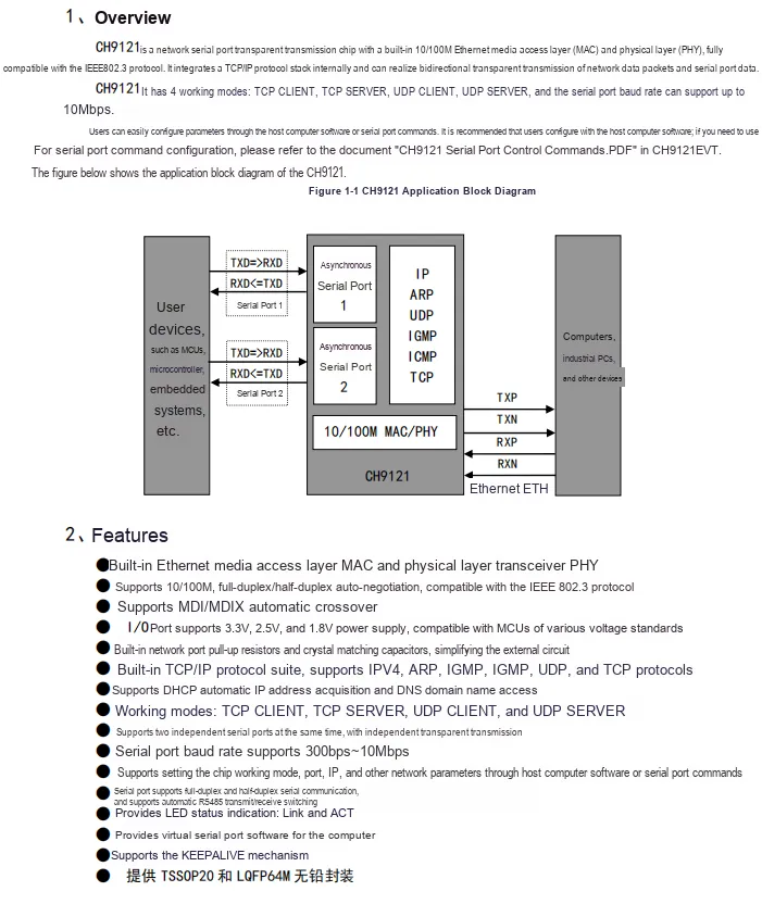
CH9121 is a serial-to-Ethernet transparent transmission chip that integrates a built-in TCP / IP protocol stack, comes with 10/100M Ethernet MAC and PHY, supports 4 network operating modes, and features a maximum serial port baud rate of up to 10Mbps.
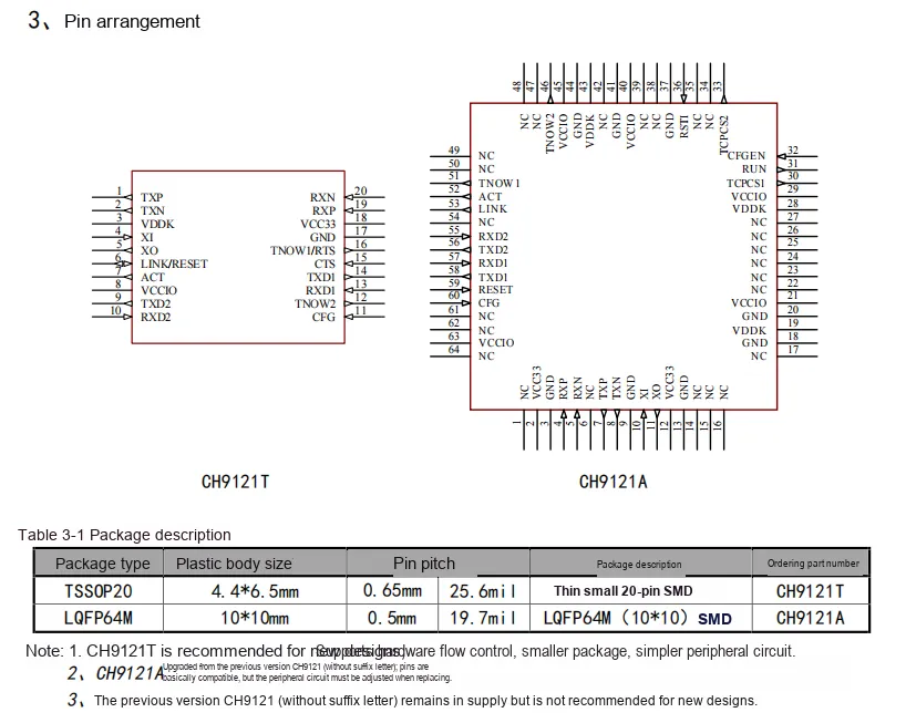
2.2 Pin Definition
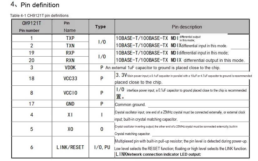
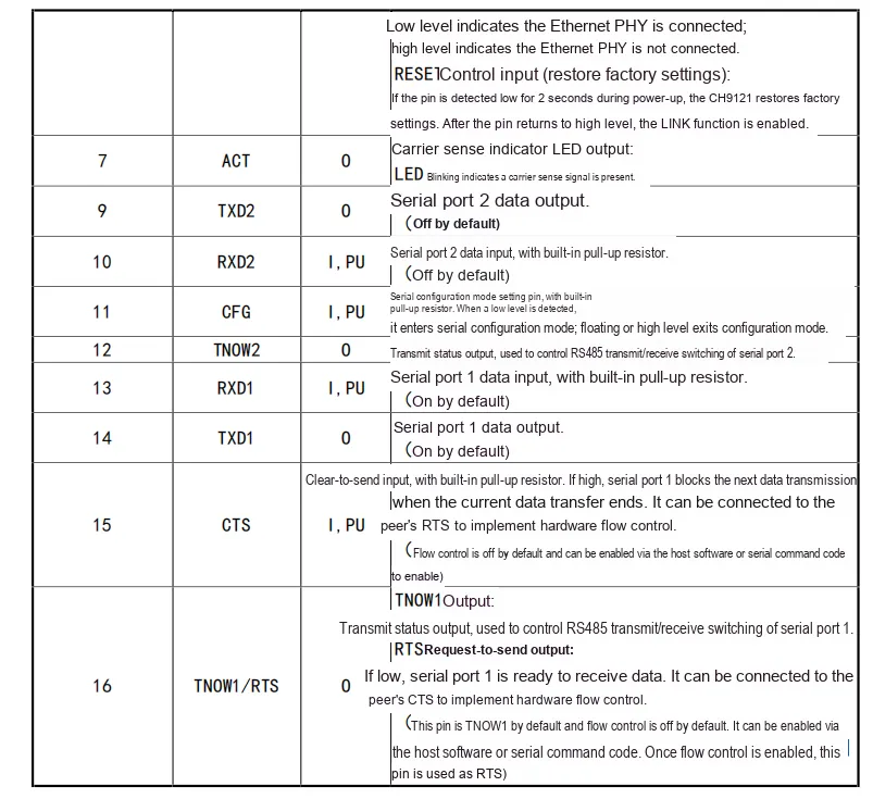
2.3 Functional Block Diagram
None.
2.4 Performance Parameters
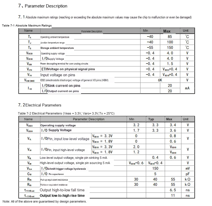
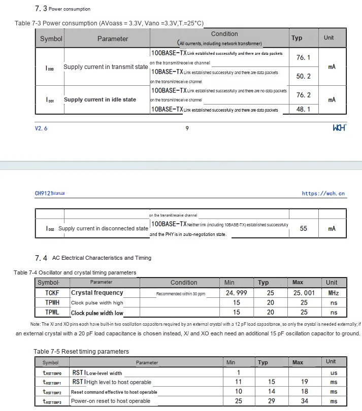
CH9121 has a typical operating supply voltage of 3.3V, its I/O ports support a wide voltage range of 1.7V to 3.6V; the typical supply current is approximately 76.1mA at 100Mbps in transmission state and around 76.2mA in idle state. It supports an industrial-grade operating temperature range from -40°C to 85°C, has a built-in 25MHz crystal oscillator circuit, features a typical reset time of 29ms, and is equipped with ESD electrostatic discharge protection capability.
2.5 Reference Circuit
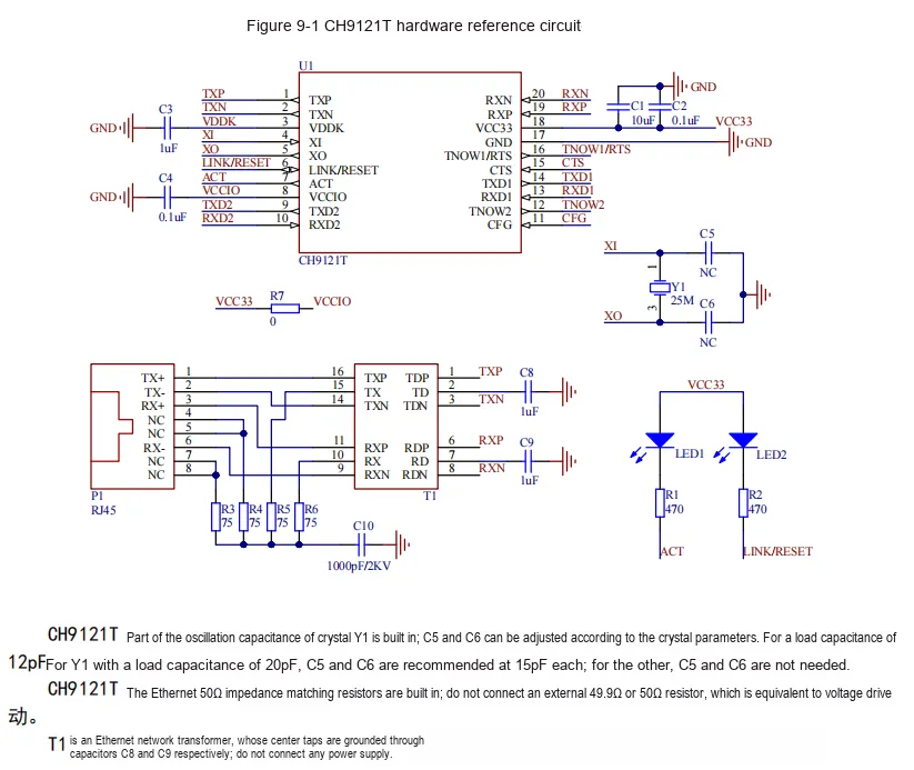
CH9121 reference circuit consists of the CH9121T chip, 25MHz crystal oscillator, network transformer T1, RJ45 Ethernet port, status indicators, decoupling capacitors and other components, which is a hardware circuit that realizes transparent data transmission between serial port and Ethernet.
2.6 Chip Configuration
None.
2.7 Communication Interfaces and Related Protocols
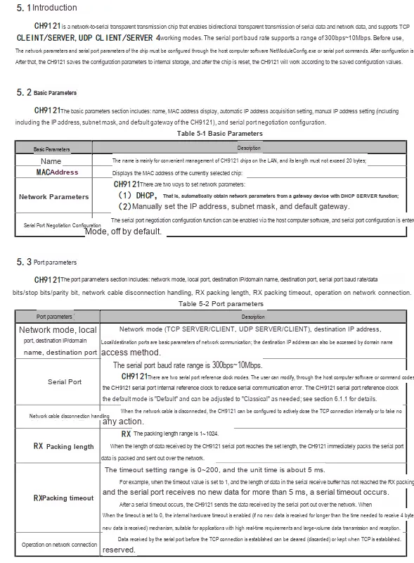
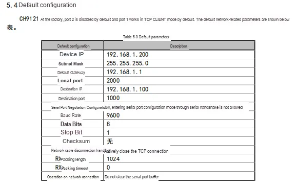
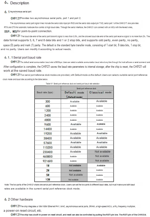

2.8 PCB Routing Precautions
None.
III. Circuit Engineering
3.1 Circuit Source Engineering
To obtain the circuit source project, please follow the official account [Freak Embedded].
3.2 Module Usage Instructions
The schematic diagram of this module is shown below:
SCH_CH9121-Based Serial to Ethernet Module-V1.0.0_2026-03-24.pdf 3.1 MB
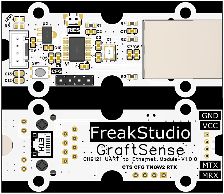
This module provides a serial port UART interface MRX and MTX: where M stands for master, meaning the MCU 's RX corresponds to the module' s TX.
Provided in the physical diagram are RES button and CFG button, wherein the RES button is used for system reset, and the CFG button is used to control entry into the serial port configuration mode.
Before using this module, we need to perform network configuration with the following software, including the working mode and IP Address:
NetModuleConfig.exe 60 KB
As shown below:
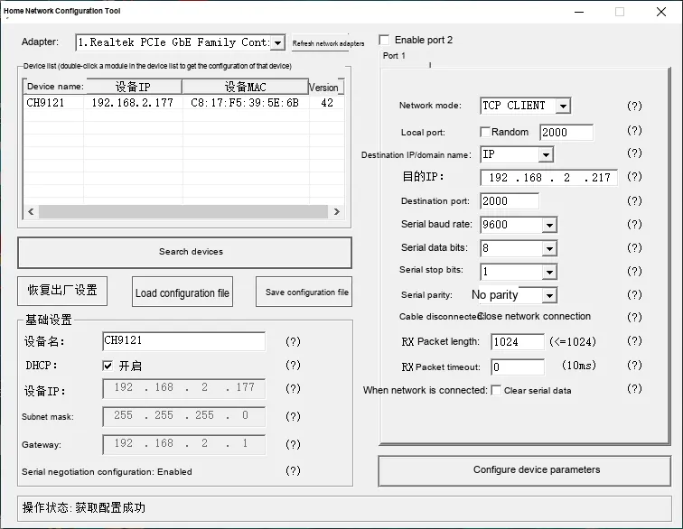
For specific configuration steps, you can refer to the tutorial below:
3.3 Application Experiment
Here, we use the GraftPort-RP2040 development board for testing, and the CH9121-based serial-to-Ethernet module uses the UART0 interface to communicate with the main controller.
Here, we first use the HY2.0-4P connection cable to connect the module to the GraftPort-RP2040 development board's UART0 interface:
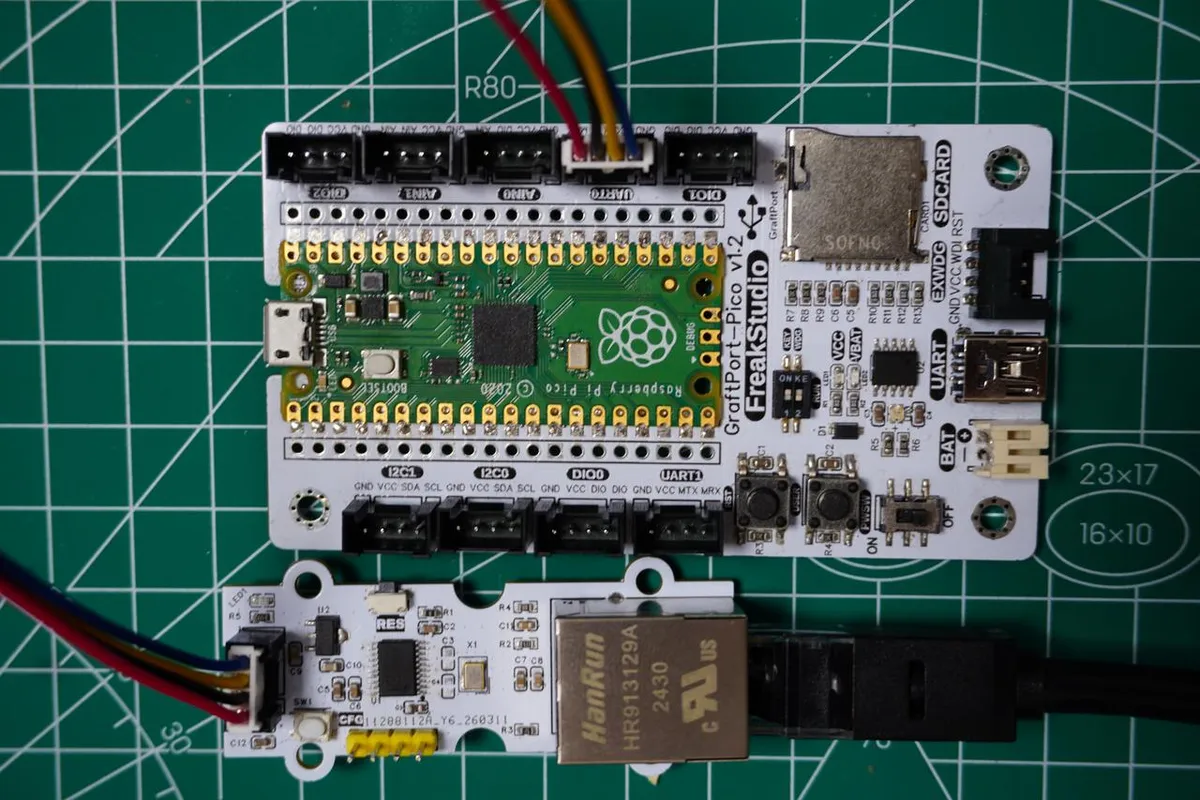
The module connections are shown in the following table:
Development Board Pins | Module Pins | Description |
Pin 16 |
|
|
Pin 17 |
|
|
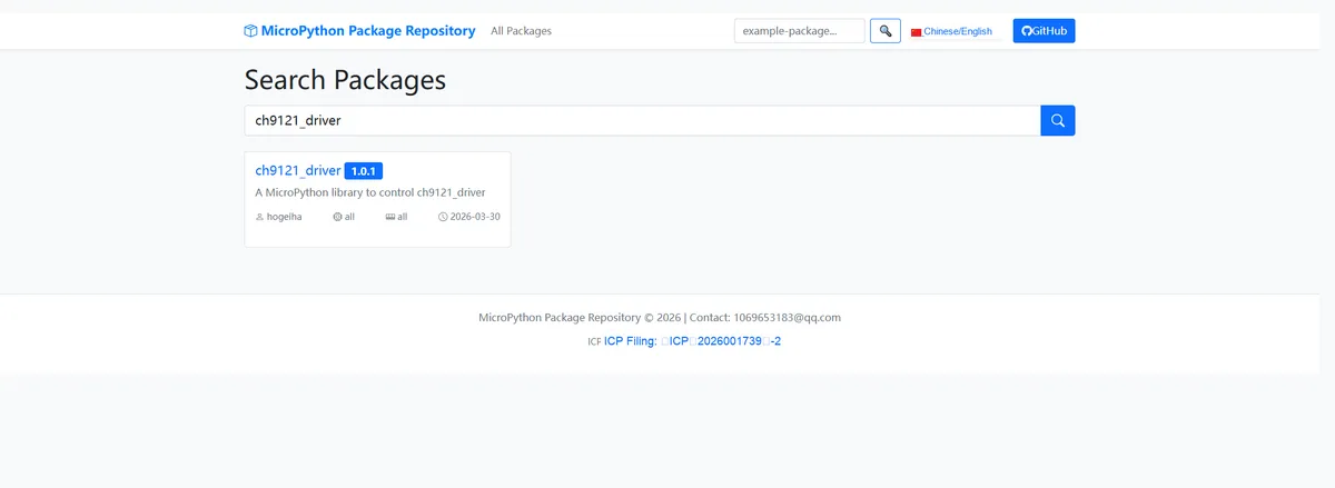
Here, we need to search for the relevant driver packages on uPyPI: https://upypi.net/zh/
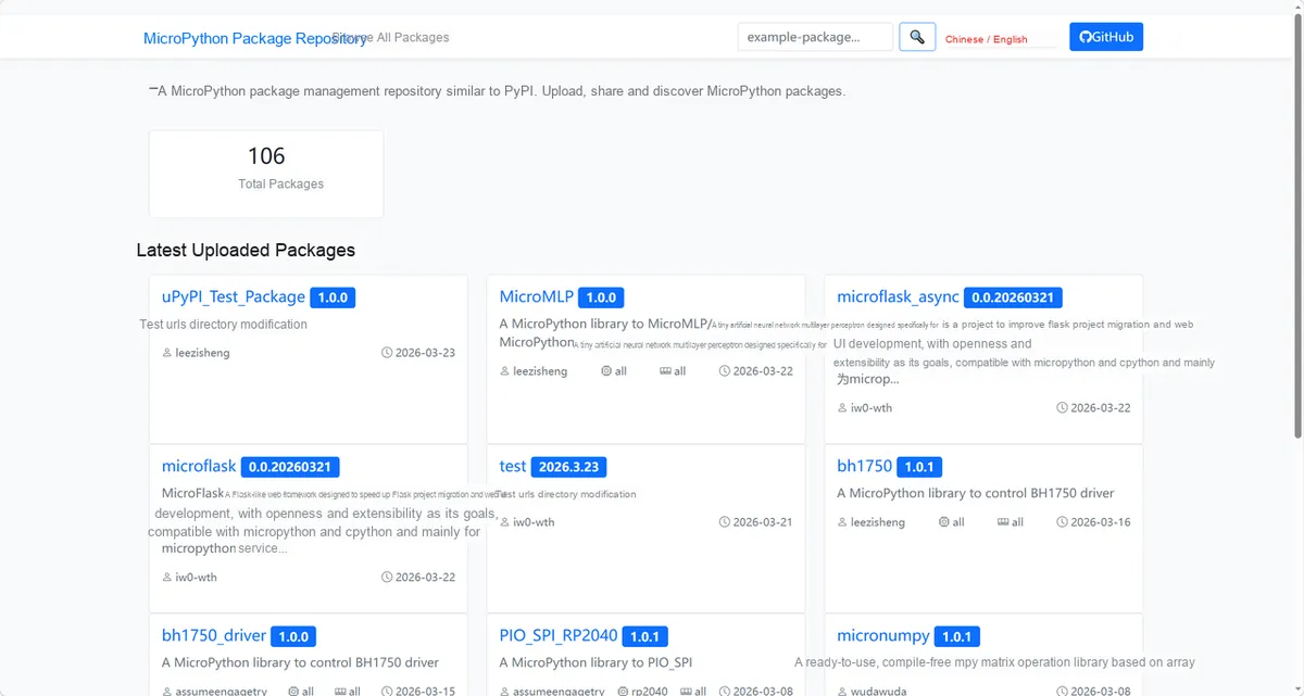
Enter ch9121_driver to search, and the following will be displayed:
Click to copy the local installation command:
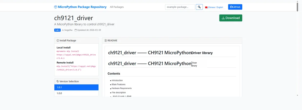
Import the module driver library code via the mip tool. Below are the usage commands for the mpremote tool:
mpremote mip install https://upypi.net/pkgs/ch9121_driver/1.0.0Import the MicroPython driver code for the CH9121-based serial-to-Ethernet module, then copy the following main.py code into our project:
# Python env   : MicroPython v1.23.0
# -*- coding: utf-8 -*-
# @Time    : 2026/3/16 9:00 PM
# @Author  : wybiral
# @File    : main.py
# @Description : CH9121 serial-to-network module example with asynchronous configuration and blocking data transmission, for Raspberry Pi Pico

# ======================================== Import Modules =========================================

# Import the MicroPython asynchronous IO module, used to configure the CH9121 asynchronously
import uasyncio as asyncio

# Import the CH9121 asynchronous driver class (original version, not modified to blocking)
import ch9121  # Note: the original CH9121 class with asynchronous methods is used here (the version not changed to blocking)

# Import the pin and UART serial control classes from the machine module
from machine import Pin, UART

# Import the time module, used for blocking delays
import time

# ======================================== Global Variables ============================================

# CH9121 network configuration parameter - gateway address, tuple format (segment 1, segment 2, segment 3, segment 4)
GATEWAY = (192, 168, 2, 254)  # Gateway address
# CH9121 network configuration parameter - target server IP address, tuple format
TARGET_IP = (192, 168, 2, 217)  # Target server IP
# CH9121 network configuration parameter - target server port number
TARGET_PORT = 2000  # Target server port

# ======================================== Functions ============================================


async def async_config(eth):
    """
    Asynchronously complete the initialization configuration of the CH9121 module
    Args:
        eth: CH9121 class instance object, an initialized serial-to-network module object

    Raises:
        None

    Notes:
        1. Wait 1 second before configuration to ensure the module power is stable
        2. Reset the module after configuration so the parameters take effect
        3. After the reset, wait 1 second before further operations

    ==========================================
    Asynchronously complete the initialization configuration of CH9121 module
    Args:
        eth: CH9121 class instance object, initialized serial to network module object

    Raises:
        None

    Notes:
        1. Wait 1 second before configuration to ensure the module is powered on stably
        2. Reset the module after configuration to make parameters take effect
        3. Wait 1 second after reset before subsequent operations
    """
    # Wait for the module power to stabilize to avoid configuration command send failures
    await asyncio.sleep(1)

    # Asynchronously configure the CH9121 as a TCP client (1=TCP_CLIENT)
    await eth.set_mode(ch9121.TCP_CLIENT)  # Set to TCP client mode
    # Asynchronously configure the CH9121 gateway address
    await eth.set_gateway(GATEWAY)  # Set the gateway
    # Asynchronously configure the CH9121 target server IP address
    await eth.set_target_ip(TARGET_IP)  # Set the target IP
    # Asynchronously configure the CH9121 target server port number
    await eth.set_target_port(TARGET_PORT)  # Set the target port
    # Asynchronously send the reset command so the configuration parameters take effect
    await eth.reset()  # Reset the module so the configuration takes effect
    # Wait for the module reset to complete to ensure the parameters load successfully
    await asyncio.sleep(1)  # Wait for the reset to complete

    # Asynchronously read the current working mode of the CH9121
    mode = await eth.get_mode()
    # Print the raw working mode value and its description
    print(f"[CH9121 Working Mode Raw Value]: {mode} (0=TCP_SERVER/1=TCP_CLIENT/2=UDP_SERVER/3=UDP_CLIENT)")

    # Asynchronously read the gateway address configured on the CH9121
    gateway = await eth.get_gateway()
    # Convert the gateway tuple to a string (e.g. 192.168.2.254)
    gateway_str = ".".join(map(str, gateway))
    # Print the configured gateway address
    print(f"[CH9121 Configured Gateway]: {gateway_str}")

    # Asynchronously read the target IP address configured on the CH9121
    target_ip = await eth.get_target_ip()
    # Convert the target IP tuple to a string
    target_ip_str = ".".join(map(str, target_ip))
    # Print the configured target IP address
    print(f"[CH9121 Configured Target IP]: {target_ip_str}")

    # Asynchronously read the target port number configured on the CH9121
    target_port = await eth.get_target_port()
    # Print the configured target port number
    print(f"[CH9121 Configured Target Port]: {target_port}")


    # Print the configuration-complete message, ready to enter blocking data transmission mode
    print("\n✅ Asynchronous configuration completed, switch to blocking data send/receive mode...")


def blocking_read_write(eth, uart):
    """
    Send test messages in a blocking loop and read the serial response data
    Args:
        eth: CH9121 class instance object (unused in this function, kept only for parameter compatibility)
        uart: UART class instance object, an initialized serial port object

    Raises:
        None

    Notes:
        1. Send directly over UART in blocking mode, bypassing the asynchronous layer
        2. Send a test message with a counter every 2 seconds
        3. After sending, wait 0.1 seconds and read the serial buffer data

    ==========================================
    Blocking loop to send test messages and read serial response data
    Args:
        eth: CH9121 class instance object (not used in this function, only for parameter compatibility)
        uart: UART class instance object, initialized serial port object

    Raises:
        None

    Notes:
        1. Directly use UART blocking send, bypass asynchronous layer
        2. Send a test message with counter every 2 seconds
        3. Delay 0.1 seconds after sending to read serial buffer data
    """
    # Initialize the message counter, used to identify each test message
    count = 1
    # Run the data send/receive loop forever
    while True:
        # Build the test message string with the counter
        test_msg = f"Test message {count}: Hello, UART loopback!"
        # Print the test message being sent
        print(f"\nSent: {test_msg}")

        # Encode the test message as a UTF-8 byte string and send it over UART (blocking)
        uart.write(test_msg.encode("utf-8"))

        # Short delay, wait for the serial port to receive response data
        time.sleep(0.1)

        # Check whether the UART buffer has data to read
        if uart.any():  # Check whether the serial port buffer has data
            # Read all available data in the buffer and decode it as a UTF-8 string
            received = uart.read(uart.any()).decode("utf-8")  # Read all available data
            # Print the received data
            print(f" Received: {received}")
        else:
            # Print a message indicating no data was received
            print(f" Received: No data (check connections)")

        # Increment the counter, used to identify the next message
        count += 1
        # Delay 2 seconds, then send the next test message
        time.sleep(2)


# ======================================== Custom Classes ============================================

# ======================================== Initialization configuration ===========================================

# Delay 3 seconds to make sure the Raspberry Pi Pico hardware and the CH9121 module are powered up and stable
time.sleep(3)
# Print the initialization message
print("FreakStudio: Initialize CH9121 module and hardware")

# Initialize the CH9121 configuration pin and set it as output (Pin 19)
cfg = Pin(19, Pin.OUT)  # CH9121 configuration pin
# Initialize UART0 with baud rate 9600, TX=Pin16, RX=Pin17 (for Raspberry Pi Pico)
uart = UART(0, baudrate=9600, tx=Pin(16), rx=Pin(17))  # Serial port configuration (baud rate 9600)
# Initialize the CH9121 async driver object, passing in the UART instance and the configuration pin
eth = ch9121.CH9121(uart, cfg)  # Initialize the CH9121 object (async version)

# ========================================  Main Program  ============================================

# Program entry point, check whether this script is run directly
if __name__ == "__main__":
    # 1. Get the asyncio event loop object
    loop = asyncio.get_event_loop()
    # Run the async configuration task until configuration is complete
    loop.run_until_complete(async_config(eth))  # Run the async configuration until it completes

    # 2. After async configuration is complete, enter the blocking data send/receive loop
    blocking_read_write(eth, uart)
The above code first completes the parameter configuration and verification of the module's TCP Client mode, gateway, target server IP and port, etc. through asynchronous IO (note that when configuring, be sure to press the CFG key!), after resetting the module to make the configuration take effect, switch to the blocking working mode, send test messages with a counter cyclically through the serial port, and read and print the response data received by the serial port in real time at the same time, which realizes the complete test function of the CH9121 module's asynchronous configuration + blocking data transmission and reception.
Burn the code, open the terminal, and launch the network debugging assistant software at the same time, then configure it according to the following figure:
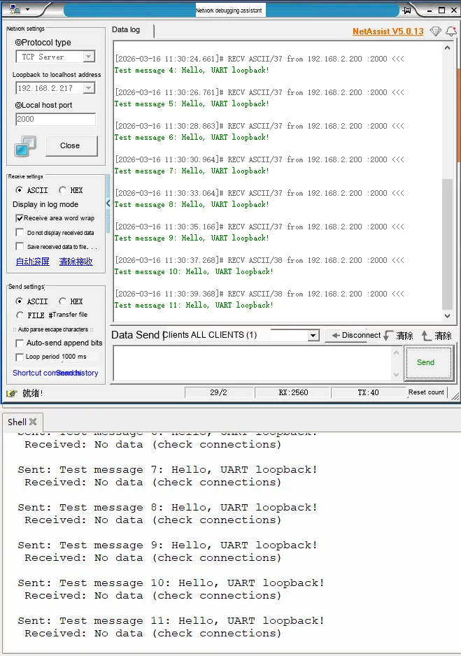
It can be seen that with the help of this module, the MCU can periodically send and receive test messages and print postback data after configuring the network.
4. Drivers
ch9121_driver-1.0.1.zip 16 KB
5. BOM & Recommended Alternative Parts
None.
VI. Revision History
Document Version | Date of Revision | Modifier | Modify Content |
v1.0 | 2026-03-24 | Ling Gaoxing | Initialize the document |
v1.0.2 | 2026-04-05 | Li Zisheng | No photos for the homepage have been taken, the production files have not been exported yet, and all other items have been sorted out. |
v1.0.3 | 2026-04-21 | Li Zisheng | The production documents have not been exported yet, while all the rest have been sorted out. |
v1.1 | 2026-04-23 | Xin Ruili | Create an open version of the document, based on the internal document version v1.0.3. |
VII. Relevant Materials
7.1 Chip Datasheet
7.1.1 Datasheet
CH9121DS1.PDF 242 KB
CH9121 Series Module User Guide.pdf 3.1 MB
CH9121 Serial Control Commands.pdf 301 KB
7.1.2 Debugging Software
NetModuleConfig.exe 60 KB
7.2 PCB Silkscreen Specific Icons