Contents
- I. Module Introduction
- II. Introduction to Major Chips
- 2.1 Chip Overview
- 2.2 Pin Definition
- 2.3 Functional Block Diagram
- 2.4 Performance Parameters
- 2.5 Reference Circuit
- 2.6 Chip Configuration
- 2.7 Communication Interfaces and Related Protocols
- 2.8 PCB Routing Precautions
- III. Circuit Engineering
- 3.1 Circuit Source Engineering
- 3.2 Module Usage Instructions
- 3.3 Application Experiment
- 4. Drivers
- 5. BOM & Recommended Alternative Parts
- VI. Revision History
- VII. Relevant Materials
- 7.1 Chip Datasheet
- 7.2 PCB Silkscreen Specific Icons
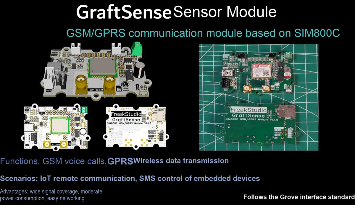
I. Module Introduction
SIM800C-based GSM/GPRS communication module, which adopts the SIM800C chip solution, supports voice, SMS and data transmission between the UART serial port and the GSM/GPRS network. It integrates a SIM card interface, a microphone/speaker circuit and a 5V-to-4V power supply circuit, reserves MCU expansion pins and status indicators, enables serial port devices to quickly access the mobile network, and is suitable for scenarios such as remote monitoring, IoT data reporting, and emergency communication.
II. Introduction to Major Chips
SIM800C is a high-performance GSM/GPRS communication module that supports voice calls, SMS sending and receiving, and GPRS data transmission. It communicates with the main controller via the UART serial port, operates on dual-band GSM networks, and is widely used in scenarios such as IoT remote monitoring and data reporting.
2.1 Chip Overview
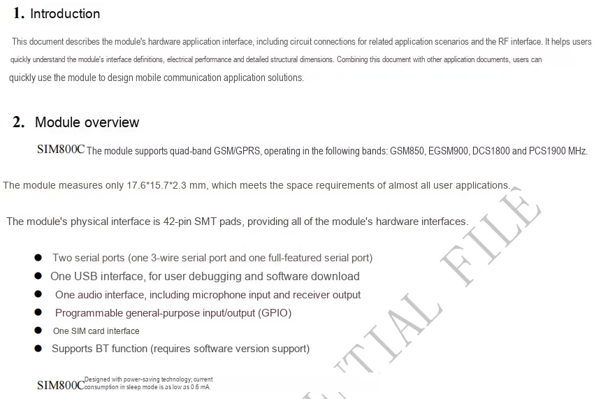
SIM800C is a compact-sized GSM/GPRS communication module in SMT package that supports quad-band. It integrates interfaces including two UART ports, USB, audio, SIM card and GPIO, supports BT function and low-power sleep mode, and is applicable to the development of mobile communication applications.
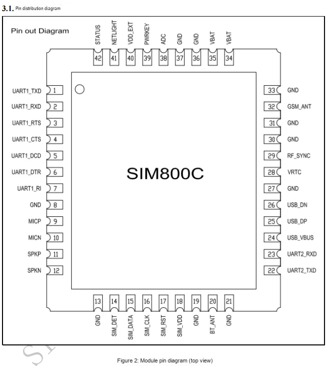
2.2 Pin Definition
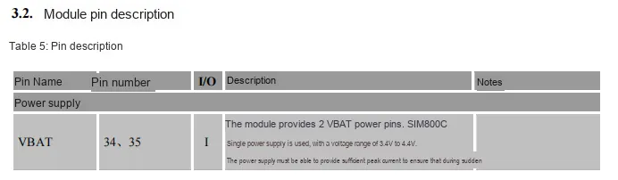
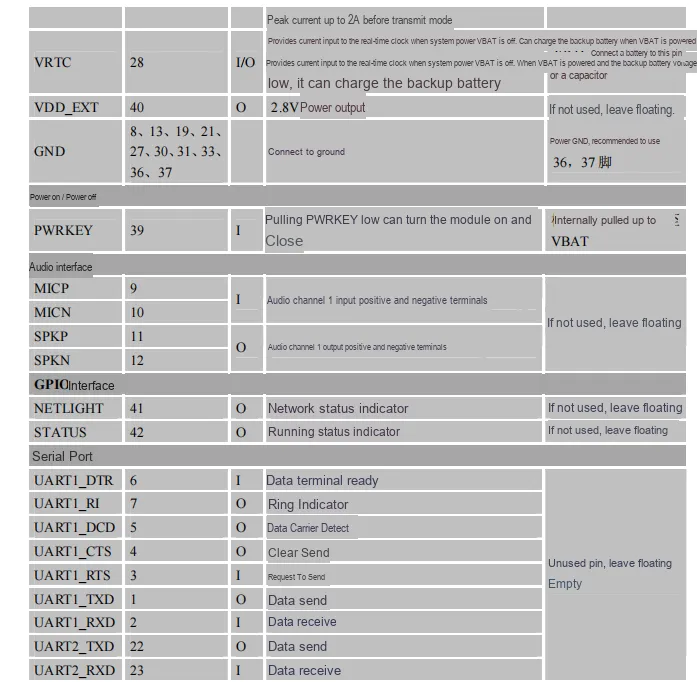
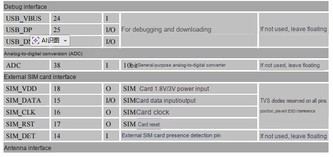

2.3 Functional Block Diagram
None.
2.4 Performance Parameters
SIM800C module power supply VBAT has a normal Scope of Work of 3.4~4.4V (absolute maximum 4.5V), with a peak current upper limit of 2A, GPIO/UART interface has a typical single-pin drive/sink current of 4mA and a maximum value of 16mA, an operating temperature range of -40~+ 85℃, a storage temperature range of -45~+ 90℃, and features wide environmental adaptability and electrical limit constraints.
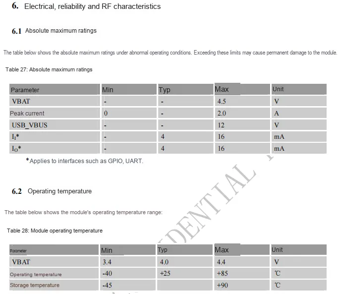
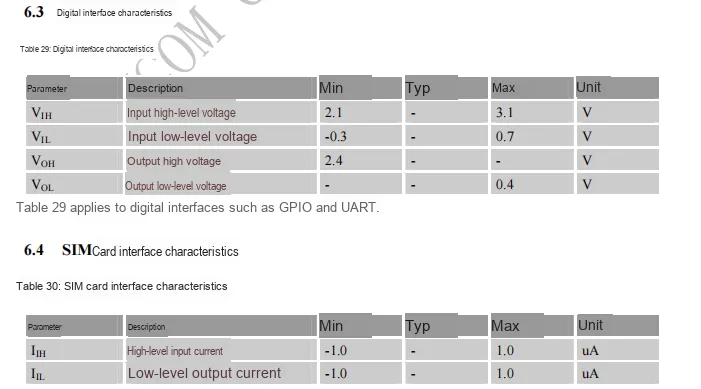
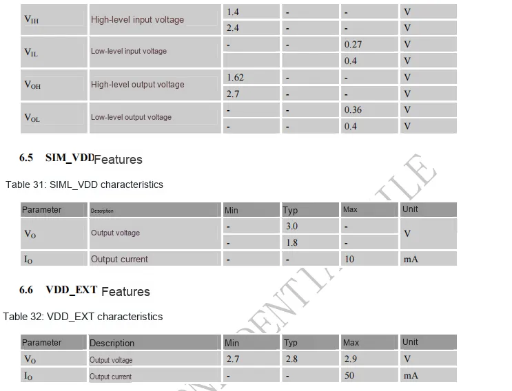
SIM800C GPIO/UART digital interface has a high-level input ≥2.1V, low-level input ≤0.7V, output high level ≥2.4V, and low level ≤0.4V;SIM card interface has a level current range of ±1.0μA, SIM_VDD typically outputs 3.0V/1.8mA (max 10mA), VDD_EXT outputs 2.7~2.9V with a maximum output current of 50mA.
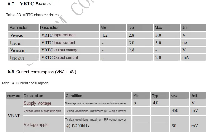
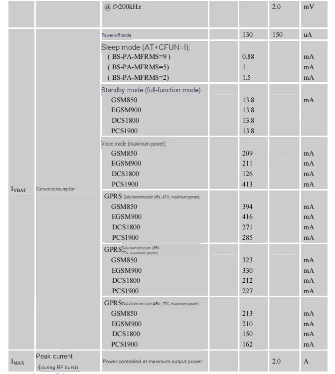
SIM800C ’s VRTC interface has an input voltage range of 1.2~3.0V (typical 2.8V), a typical input current of 3.0μA with a maximum of 5.0μA, a typical output voltage of 2.8V, and a maximum output current of 2.0mA; when VBAT = 4V, the current consumption in shutdown mode is only 130~150μA, and the current consumption increases progressively in sleep/standby/voice/ GPRS data transmission modes, with a peak current up to 2.0A during RF bursts.
2.5 Reference Circuit
None.
2.6 Chip Configuration
None.
2.7 Communication Interfaces and Related Protocols
AT For relevant materials of commands, please refer to the attached document *SIM800_Series_AT_Command_Manual_V1.10*.
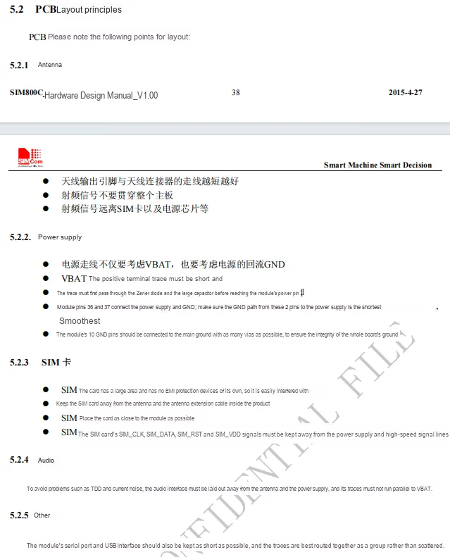
2.8 PCB Routing Precautions
III. Circuit Engineering
3.1 Circuit Source Engineering
To obtain the circuit source project, please follow the official account [Freak Embedded].
3.2 Module Usage Instructions
The schematic diagram of this module is shown below:
SCH_GSM GPRS Communication Module Based on SIM800C-V1.0.0_2026-03-24.pdf 2.8 MB
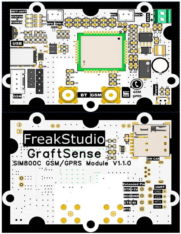
This module provides a serial port UART interface MRX and MTX: where M stands for master, meaning the MCU 's RX corresponds to the module' s TX.
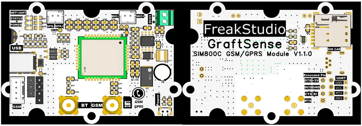
The physical device provides multiple interfaces, and the functions of each interface are as follows:
- Three indicator lights:
NETLIGHTis the network status indicator,STATUSis the operation status indicator,POWERis the power indicator. - The module provides a speaker interface
SPK-,SPK+and a microphone interfaceMIC-,MIC+. - The external power supply interface adopts
DB125-2.54-2P, with the silkscreen marking:5V/2A. - The module is equipped with 2 antenna circuits, and all antenna interfaces are
SMA, of whichBTis the Bluetooth antenna interface, andGSMis theGSMantenna interface. PowerThe screen-printed button is used to control the power on/off function of the module.
The back of the module is equipped with SIM card interface, and we also provide expansion pin headers here:
| Pin Label | I/O Direction (Module Side) | Level Standard | Core function | Details | Typical Use Case |
|---|---|---|---|---|---|
| DTR | Input | 1.8V/3.3V/5V compatible | Data Terminal Ready | Control signal sent from the host MCU to the SIM800C to notify the module that the terminal (MCU) is ready / not ready; active low. Can be used to put the module into / take it out of power-saving mode, hang up the current call, etc. | 1. Puts the SIM800C into PSM power-saving mode; 2. Pull low during a call to hang up; 3. Serial flow control assist |
| +6V | Power Input | DC 6V ±5% | Main power input of the module | 6V supply input of the module; internally converted to 4V by the TPS54331 buck chip to power the SIM800C core. Peak current during GSM transmission can reach 1.5~2A, so the power supply must be able to handle the load. | Powers the module; a power adapter of 6V/2A or higher is recommended |
| DCD | Output | 1.8V/3.3V/5V compatible | Data Carrier Detect | Network status signal output from the SIM800C to the MCU, indicating whether a data carrier is present: - Low level: GPRS / dial-up network carrier detected (connected to network / dialed) - High level: No carrier (not connected to network / link disconnected) | 1. Real-time monitoring of the module's network connection status; 2. Link status indication during dial-up internet access |
| GND | Common Ground | 0V | System reference ground | Power ground and signal ground of the module, and the reference potential for all signals; it must share a common ground with the host MCU system, otherwise communication errors, interference and other problems will occur. | Common ground with the MCU and peripherals to suppress common-mode interference |
| CTS | Input | 1.8V/3.3V/5V compatible | Clear To Send | Hardware flow control signal sent from the MCU to the SIM800C; active low: - Low level: MCU is idle, SIM800C is allowed to send data - High level: MCU is busy, SIM800C is not allowed to send data | Hardware flow control to prevent data overflow and packet loss during high-speed UART communication |
| RI | Output | 1.8V/3.3V/5V compatible | Ring Indicator | Interrupt trigger signal output from the SIM800C to the MCU, triggered on an incoming call / received SMS: - Incoming call ring: outputs a low-level pulse with a 125ms period - SMS received: outputs a single low-level pulse | 1. Incoming call / SMS wakes up a sleeping MCU; 2. External interrupt event notification; 3. Wake-up source for low-power IoT devices |
| RTS | Output | 1.8V/3.3V/5V compatible | Request To Send | Hardware flow control signal output from the SIM800C to the MCU; active low: - Low level: SIM800C has data to send and requests the MCU to receive - High level: SIM800C has no data to send | Hardware flow control; works with CTS to implement full-duplex flow control and avoid data loss |
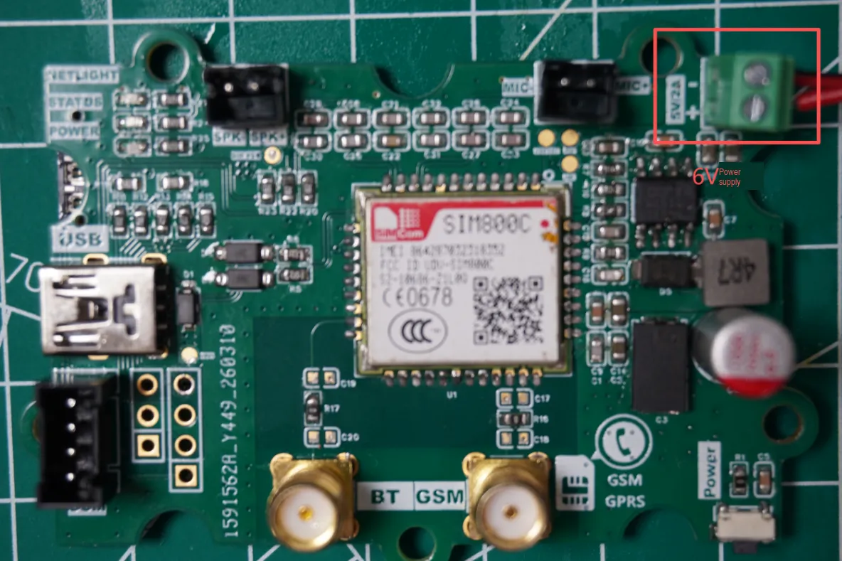
Note: This module requires a power input of 6V 2A.
3.3 Application Experiment
Here, we use the GraftPort-RP2040 development board for testing, and the SIM800C-based GSM & GPRS communication module communicates with the main controller via the UART interface.
Here, we first use the HY2.0-4P connection cable to connect the module to the GraftPort-RP2040 development board's UART0 interface:
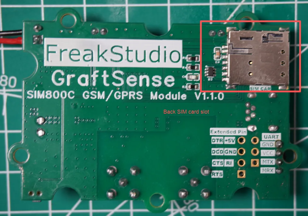
Insert a properly activated SIM card into the card slot on the back of the module:
The module requires a 6V/2A power supply to ensure normal operation!
The module connections are shown in the following table:
Development Board Pins | Module Pins | Description |
Pin 16 |
|
|
Pin 17 |
|
|
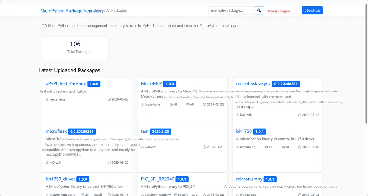
Here, we need to search for the relevant driver packages on uPyPI: https://upypi.net/zh/
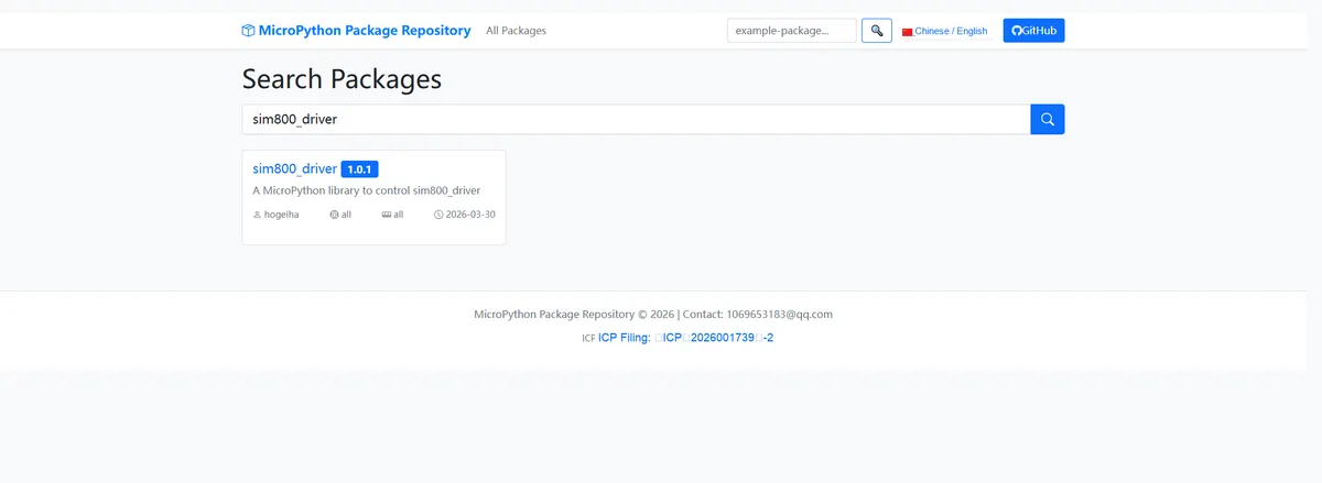
Enter sim800_driver to search, and the following will be displayed:
Click to copy the local installation command:
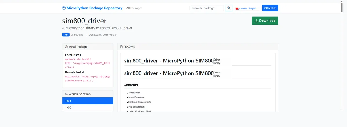
Import the module driver library code via the mip tool. Below are the usage commands for the mpremote tool:
mpremote mip install https://upypi.net/pkgs/sim800_driver/1.0.0Import the SIM800C-based GSM & GPRS communication module - MicroPython driver code, then copy the following main.py code into our project:
# Python env   : MicroPython v1.23.0
# -*- coding: utf-8 -*-
# @Time    : 2025/9/8 5:20 PM
# @Author  : alankrantas
# @File    : main.py
# @Description : SIM800 module basic information query example, with optimized print format that extracts key information

# ======================================== Import Modules =========================================

# Import the SIM800 SMS extension class
from sim800 import SIM800SMS

# Import the UART and Pin classes from the machine module, used for hardware pin and serial port configuration
from machine import UART, Pin

# Import the time module, used for delays
import time

# ======================================== Global Variables ============================================

# ======================================== Functions ============================================


def parse_phone_number(response: bytes) -> str:
    """
    Parse the phone number response data and extract the key phone number information
    Args:
        response (bytes): Raw response byte data

    Raises:
        None

    Notes:
        On parse failure, return a friendly unknown message to avoid crashing the program

    ==========================================
    Parse phone number response data to extract key phone number information
    Args:
        response (bytes): Raw response byte data

    Raises:
        None

    Notes:
        Return a friendly unknown prompt when parsing fails to avoid program crash
    """
    try:
        # Convert the byte data to a string and clean up line breaks
        resp_str = response.decode("utf-8").replace("\r\n", "")
        # Extract the phone number part
        phone_part = resp_str.split("+CNUM:")[1].split(",")[1].replace('"', "")
        return f"SIM Card Phone Number: {phone_part if phone_part else 'Not configured'}"
    except (IndexError, ValueError):
        return "SIM Card Phone Number: Unknown"


def parse_manufacturer(response: bytes) -> str:
    """
    Parse the manufacturer response data and extract the module manufacturer information
    Args:
        response (bytes): Raw response byte data

    Raises:
        None

    Notes:
        On parse failure, return a friendly unknown message to avoid crashing the program

    ==========================================
    Parse manufacturer response data to extract module manufacturer information
    Args:
        response (bytes): Raw response byte data

    Raises:
        None

    Notes:
        Return a friendly unknown prompt when parsing fails to avoid program crash
    """
    try:
        # Convert the byte data to a string and clean up line breaks
        resp_str = response.decode("utf-8").replace("\r\n", "")
        # Extract the manufacturer name part
        manufacturer = resp_str.split("OK")[0].strip()
        return f"Module Manufacturer: {manufacturer if manufacturer else 'Unknown'}"
    except (IndexError, ValueError):
        return "Module Manufacturer: Unknown"


def parse_signal_quality(response: bytes) -> str:
    """
    Parse the signal quality response data and extract the signal strength and bit error rate
    Args:
        response (bytes): Raw response byte data

    Raises:
        None

    Notes:
        RSSI ranges from 0-31 (higher value means better signal), 99 means no signal; BER ranges from 0-7 (lower value means lower bit error rate), 99 means unknown

    ==========================================
    Parse signal quality response data to extract signal strength and bit error rate
    Args:
        response (bytes): Raw response byte data

    Raises:
        None

    Notes:
        RSSI range 0-31 (higher value = better signal), 99 means no signal; BER range 0-7 (lower value = lower bit error rate), 99 means unknown
    """
    try:
        # Convert the byte data to a string and clean up line breaks
        resp_str = response.decode("utf-8").replace("\r\n", "")
        # Extract the signal quality value part
        csq_part = resp_str.split("+CSQ:")[1].split("OK")[0].strip()
        # Split the signal strength and bit error rate
        rssi, ber = csq_part.split(",")
        # Generate the signal strength description text
        rssi_desc = "No signal" if rssi == "99" else f"{rssi} (0-31, higher value = better signal)"
        # Generate the bit error rate description text
        ber_desc = "Unknown" if ber == "99" else f"{ber} (0-7, lower value = lower bit error rate)"
        return f"Signal Quality - RSSI: {rssi_desc}, BER: {ber_desc}"
    except (IndexError, ValueError):
        return "Signal Quality: Unknown"


def parse_serial_number(response: bytes) -> str:
    """
    Parse the serial number response data and extract the module IMEI number
    Args:
        response (bytes): Raw response byte data

    Raises:
        None

    Notes:
        On parse failure, return a friendly unknown message to avoid crashing the program

    ==========================================
    Parse serial number response data to extract module IMEI number
    Args:
        response (bytes): Raw response byte data

    Raises:
        None

    Notes:
        Return a friendly unknown prompt when parsing fails to avoid program crash
    """
    try:
        # Convert the byte data to a string and clean up line breaks
        resp_str = response.decode("utf-8").replace("\r\n", "")
        # Extract the IMEI number part
        imei = resp_str.split("OK")[0].strip()
        return f"Module IMEI Number: {imei if imei else 'Unknown'}"
    except (IndexError, ValueError):
        return "Module IMEI Number: Unknown"


# ======================================== Custom Classes ============================================

# ======================================== Initialization configuration ===========================================

# Delay 3 seconds to ensure the SIM800 module has finished initializing
time.sleep(3)
# Print the module initialization complete message
print("FreakStudio: SIM800 module initialized successfully")
# Configure UART0 serial port, baud rate 9600, TX pin 16, RX pin 17 (for Raspberry Pi Pico)
uart = UART(0, baudrate=9600, tx=Pin(16), rx=Pin(17))
# Instantiate the SIM800SMS class, passing in the configured UART object
sim800 = SIM800SMS(uart=uart)

# ========================================  Main Program  ============================================

# Get the phone number response data, then parse and print it
phone_resp = sim800.get_phone_number()
print(parse_phone_number(phone_resp))

# Get the manufacturer response data, then parse and print it
manufacturer_resp = sim800.get_manufacturer()
print(parse_manufacturer(manufacturer_resp))

# Get the signal quality response data, then parse and print it
signal_resp = sim800.get_signal_quality()
print(parse_signal_quality(signal_resp))

# Get the serial number response data, then parse and print it
serial_resp = sim800.get_serial_number()
print(parse_serial_number(serial_resp))
Burn the code, open the terminal, and the output is as follows:

Note: Affected by the gradual phase-out of national 2G/3G networks, this example only parses and prints the basic SIM card information, and does not implement 2G/3G communication functions.
4. Drivers
sim800_driver-1.0.1.zip 34 KB
5. BOM & Recommended Alternative Parts
None.
VI. Revision History
Document Version | Date of Revision | Modifier | Modify Content |
v1.0 | 2026-03-24 | Ling Gaoxing | Initialize the document |
v1.0.1 | 2026-04-21 | Li Zisheng | The production documents have not been exported yet, while all the rest have been sorted out. |
v1.1 | 2026-04-23 | Xin Ruili | Create an open version of the document, based on the internal document version v1.0.1. |
VII. Relevant Materials
7.1 Chip Datasheet
SIM800C Hardware Design Manual.pdf 2.4 MB
SIM800 Series_AT Command Manual_V1.10.pdf 3.9 MB
7.2 PCB Silkscreen Specific Icons