Contents
- I. Module Introduction
- II. Introduction to Main Chips
- 2.1 Chip Overview
- 2.2 Pin Definition
- 2.3 Functional Block Diagram
- 2.4 Performance Parameters
- 2.5 Reference Circuit
- 2.6 Chip Configuration
- 2.7 Communication Interfaces and Related Protocols
- 2.8 PCB Routing Precautions
- III. Instructions for Circuit Engineering and Module Usage
- 3.1 Circuit Source Engineering
- 3.2 Module Usage Instructions
- 3.3 Application Experiment
- IV. Drivers
- 5. BOM & Recommended Alternative Parts
- VI. Revision History
- VII. Relevant Materials
- 7.1 Chip Datasheet
- 7.2 Unique Icons for PCB Silk Screen
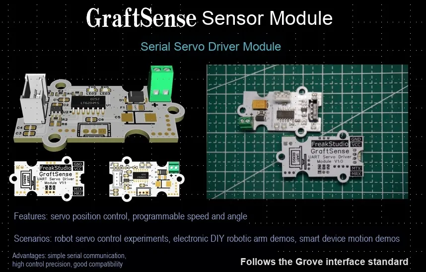
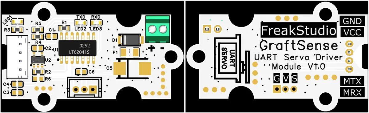
I. Module Introduction
Serial Servo Driver Module adopts a full-duplex to half-duplex circuit design, realizes serial communication adaptation through three-stage buffers and inverters, and can drive 1 channel of serial bus servos; it integrates power/communication indicators, reverse connection protection diodes and resettable fuses (overcurrent protection), and is equipped with large-capacity tantalum capacitors to ensure stable power supply, supporting UART interface (MTX / MRX) to communicate with the main controller. It is suitable for scenarios such as robot control and maker development, and provides a stable drive and control solution for serial devices and servos.
II. Introduction to Main Chips
This module mainly relies on 74AHC1G04W5 inverter chip and 74HC126D buffer chip to form a full-duplex to half-duplex circuit.
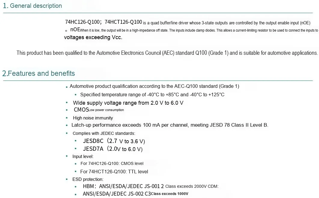
74HC126D - Q100J is a 4-channel CMOS component from NXP that complies with the AEC-Q100 automotive standard non-inverting tri-state buffer / line driver, which operates at a voltage of 2-6V, with an operating temperature range of -40°C to 125°C, features a high/low level output current of 7.8mA, boasts low power consumption and strong compatibility, and is suitable for signal buffering and driving scenarios in automotive and general industrial digital circuits.
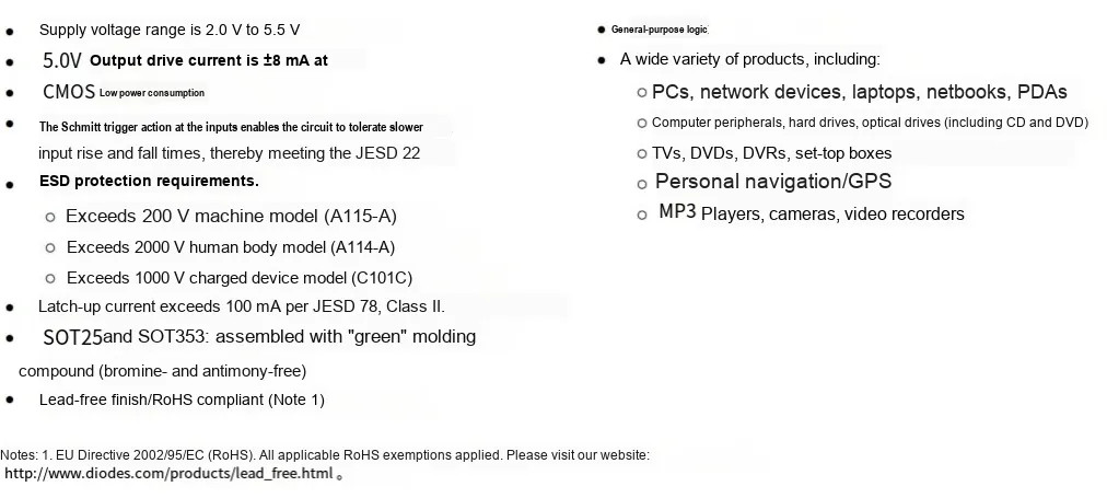
74AHC1G04W5 - 7 is a single-channel high-speed CMOS inverter chip, featuring an operating voltage of 2 - 5.5V, an operating temperature range of -40°C to 125°C, a maximum propagation delay of only 6.5ns at 5V, Schmitt trigger inputs for strong anti-interference performance, low power consumption, and a drive capability of ±8mA, making it suitable for signal inversion conversion scenarios in various digital circuits.
2.1 Chip Overview
2.1.1 Overview of 74AHC1G04W5 - 7
2.1.2 Overview of 74HC126D - Q100J
2.2 Pin Definition
2.2.1 74AHC1G04W5 - Pin Definition for the 7-Pin Package
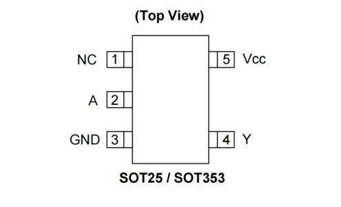
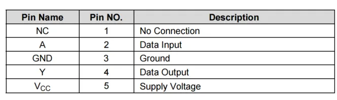
2.2.2 Pin Definition of 74HC126D - Q100J
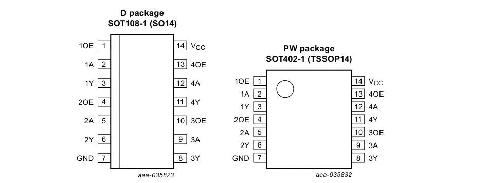
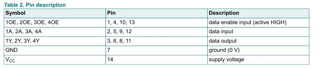
2.3 Functional Block Diagram
74AHC1G04W5 - 7 Functional Block Diagram
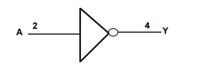
As shown in the figure, 74AHC1G04W5-7 is an inverter, which means that when terminal A inputs 1, terminal Y outputs 0.
74HC126D - Q100J has no associated functional block diagram.
2.4 Performance Parameters
2.4.1 74AHC1G04W5 - 7 Electrical Parameters
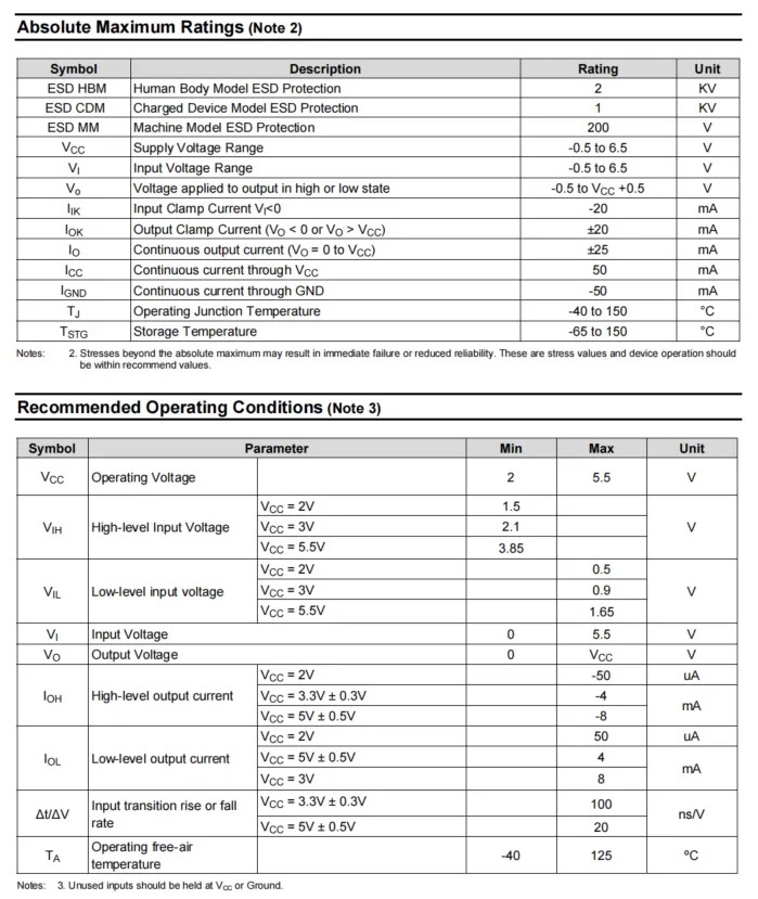
74AHC1G04W5 - 7 electrical parameters are shown in the table above, and some of the parameters are as follows:
Absolute Maximum Ratings
- ESD Protection: Human Body Model 2KV, Charged Device Model 1KV, Machine Model 200V.
- Supply Voltage Range: -0.5 to 6.5V; the input voltage and output voltage ranges are the same as this, avoid voltage exceeding the limit to prevent damage to the chip.
- Input clamp current: -20mA, output clamp current ±20mA.
- Continuous output current: ±25mA, continuous current at the power supply terminal: 50mA, continuous current at the ground terminal: -50mA.
- Operating junction temperature: -40~150℃, storage temperature: -65~150℃.
Recommended Operating Conditions
- Operating Voltage: 2~5.5V, which is the power supply range for normal operation of the chip.
- Input high level: Varies with VCC: ≥1.5V at 2V, ≥2.1V at 3V, ≥3.85V at 5.5V; Input low level: ≤0.5V at 2V, ≤0.9V at 3V, ≤1.65V at 5.5V.
- Input Voltage: 0~5.5V, Output Voltage: 0~VCC.
- High-level output current: Varies with VCC: -50μA at 2V, -4mA at 3.3V±0.3V, -8mA at 5V±0.5V; Low-level output current: 50μA at 2V, 4mA at 3.3V±0.3V, 8mA at 5V±0.5V.
- Input conversion rate: 100ns/V at 3.3V±0.3V, 20ns/V at 5V±0.5V.
- Operating temperature: -40~125°C.
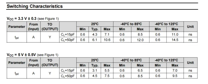
74AHC1G04W5 - 7 Switching Characteristics
2.4.2 74HC126D - Q100J Electrical Parameters
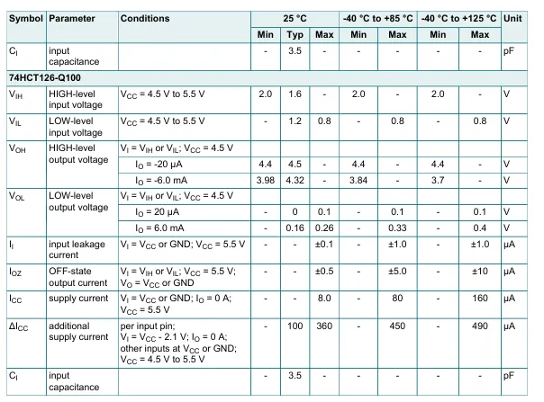
74HC126D - Q100J electrical parameters are shown in the table above, and some of the parameters are as follows:
- Input capacitance: typically 3.5 pF, which affects the frequency characteristics of the input signal.
- Input high level: minimum value 2.0V, typical value 1.6V.
- Input low level: maximum value 0.8V, typical value 1.2V.
- High-level output voltage: Under different load currents, the minimum value is 3.7V (within the temperature range of -40°C to + 125°C), which ensures the high-level output capability.
- Low-level output voltage: maximum value 0.1V (under different conditions).
- Input leakage current: maximum value ±1.0μA, low quiescent current for reduced power consumption.
- Off-state output current: maximum value ±10μA, with low leakage current when turned off.
- Supply Current: Maximum 160μA (at -40°C to + 125°C), with low quiescent power consumption.
- Additional power supply current: maximum value 490μA, which reflects the additional power consumption caused by the input pins.
2.5 Reference Circuit
None.
2.6 Chip Configuration
74HC126D - Q100J and 74AHC1G04W5 - 7 chips are a three-state buffer and an inverter respectively, and no additional configuration is required when using them.
2.7 Communication Interfaces and Related Protocols
None.
2.8 PCB Routing Precautions
None.
III. Instructions for Circuit Engineering and Module Usage
3.1 Circuit Source Engineering
To obtain the circuit source project, please follow the official account [Freak Embedded]
3.2 Module Usage Instructions
The schematic diagram of this module is shown below:
SCH_Serial Servo Driver Module_v1.0_2025-11-23.pdf 2.9 MB
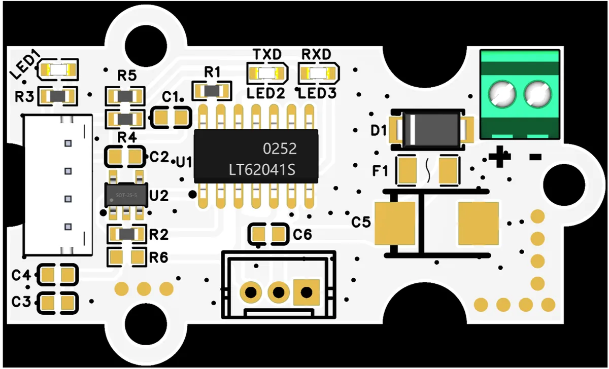
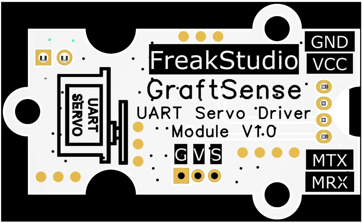
This module provides a UART interface: the MRX (corresponding to the UART MCU serial port RXD) is actually connected to the module's TXD pin, and the MTX (corresponding to the MCU serial port TX) is actually connected to the module's RXD pin;do not cross-connect them under any circumstances.
As shown in the figure below, CN1 is the connection terminal of the serial bus servo, and the pin sequence is as shown in the rear view.
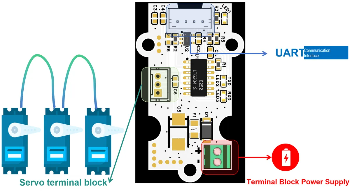
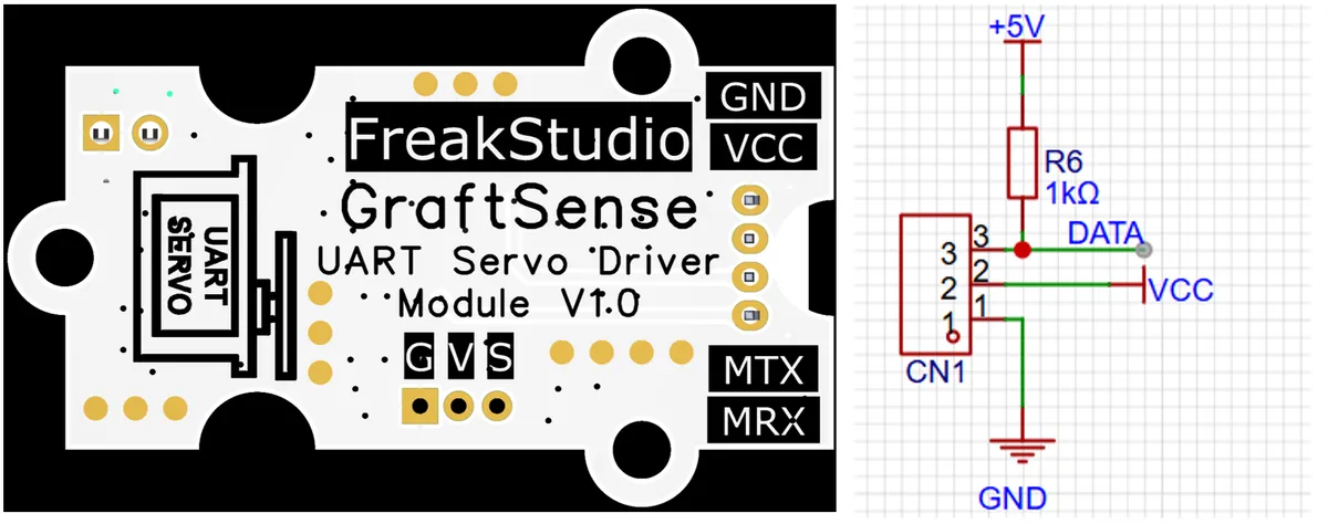
Here, the core circuit is implemented with tri-state buffers and inverters to realize the design of converting serial communication from full-duplex to half-duplex:
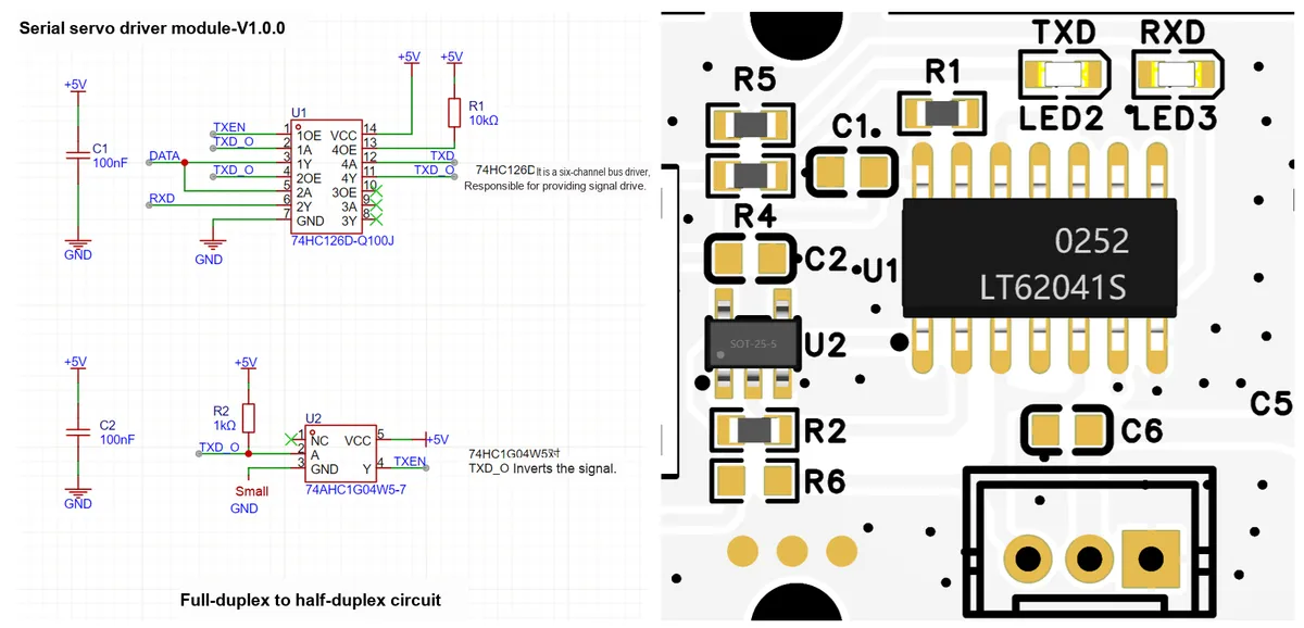
74HC126D (U1) is responsible for enhancing the driving capability of the serial port signal, 74HC1G04W5 (U2) inverts the TXD_O signal to generate the TXEN enable signal, which controls the communication direction of 74HC126D.
In addition, we use SS34 diodes and a fuse with a trip current of 3A and a holding current of 1.5A, which can ensure that the serial bus servo operates at a maximum power supply of 3A.
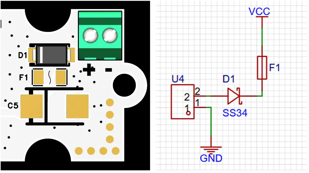
Meanwhile, we use a 220μF large capacitor for power supply filtering, paired with small capacitors to eliminate high-frequency noise from the power supply.
3.3 Application Experiment
Here, we use the GraftPort-RP2040 development board for testing, and will use the serial servo driver module to control the Hiwonder LX-1501 bus servo; in addition, the serial servo driver module communicates with the main controller via the UART interface. Meanwhile, with the help of the LM2596S adjustable power supply module, we provide an independent external 5V power supply for the serial servo driver module.
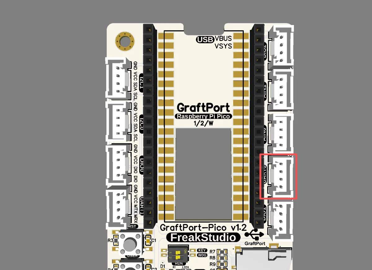
Here, we first use the HY2.0-4P cable to connect the module to the GraftPort-RP2040 development board's UART0 interface:
Here, we use the LM2596S adjustable power supply module to provide external 5V power supply for the serial servo driver module (the servos connected to this module can only operate with external power supply).
The module connections are shown in the following table:
development board pins | Module Pins | Description |
Pin 16 |
|
|
Pin 17 |
|
|
- |
| Connect Hiwonder LX-1501 Bus Servo |
power supply terminal |
|
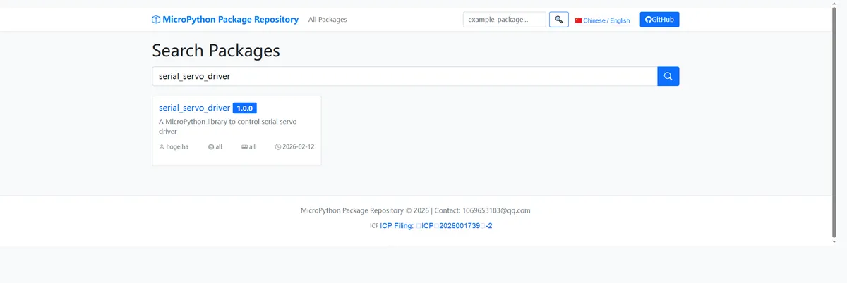
Here, we need to search for the relevant driver packages on uPyPI: https://upypi.net/zh/
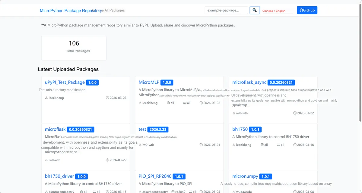
Enter serial_servo_driver to search, and the following will be displayed:
Click to copy the local installation command:
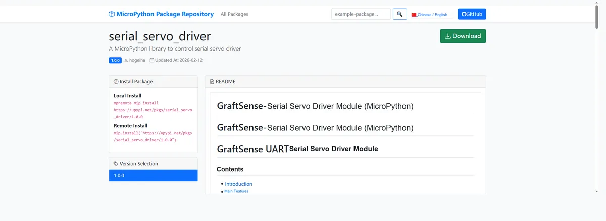
Here, we can import the module driver library code via the mip tool. Below are the usage commands for the mpremote tool:
mpremote mip install github:FreakStudioCN/GraftSense-Drivers-MicroPython/motor_drivers/serial_servo_driverAfter importing the serial servo driver module - MicroPython driver code, copy the following main.py code into our project:
# Python env   : MicroPython v1.23.0
# -*- coding: utf-8 -*-
# @Time    : 2025/09/17 16:35
# @Author  : 侯钧瀚
# @File    : main.py
# @Description : Serial servo control example
# @License : CC BY-NC 4.0

# ======================================== Import Modules =========================================
# MicroPython internal module
from machine import UART, Pin
# Import time to provide delay and timing control
import time
# Import the serial servo control board module
from serial_servo import SerialServo
# ======================================== Global Variables ============================================

# ======================================== Functions ============================================
# ======================================== Custom Classes ============================================

# ======================================== Initialization ==========================================
# Delay 3 s to wait for the device to finish powering up
time.sleep(3)
# Print debug message
print("FreakStudio:  Serial Servo Test ")
# Configure the UART serial port
uart = UART(0, baudrate=115200, tx=Pin(16), rx=Pin(17))

# Initialize the serial servo control class
servo = SerialServo(uart)

while True:
    servo.move_servo_immediate(servo_id=4, angle=0.0, time_ms=1000)
    time.sleep(2)
    angle, time_ms = servo.get_servo_move_immediate(servo_id=4)
    print(f"Servo ID: 4, Angle: {angle}, Time: {time_ms}")
    servo.move_servo_immediate(servo_id=4, angle=90.0, time_ms=1000)
    time.sleep(2)
    # Get the servo's angle and time settings
    angle, time_ms = servo.get_servo_move_immediate(servo_id=4)
    print(f"Servo ID: 4, Angle: {angle}, Time: {time_ms}")
To flash the code, open a terminal and use the mpremote tool to connect to the main controller; the output is as follows:
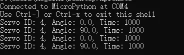
It can be seen that the servo with the corresponding ID will rotate in the corresponding type according to the code (the ID of the serial servo we use is 4).
IV. Drivers
serial_servo_driver.zip 20 KB
5. BOM & Recommended Alternative Parts
None.
VI. Revision History
Document Version | Revision Date | Modifier | Revised Content |
v1.0 | 2025-11-23 | Li Zisheng | Initialize Document The BOM sheet has not been finally checked, the driver has not been re-verified, and the 3.3 application experiment Not yet specified. |
v1.1 | 2025-12-29 | Li Zisheng | Added application experiments and production files |
v1.2 | 2025-12-31 | Sin Ruili | Create an open version of the document based on the internal document version v1.1. |
v1.3 | 2026-03-29 | Sin Ruili | Modified the application experiment section |
VII. Relevant Materials
7.1 Chip Datasheet
C460486_Inverter_74AHC1G04W5-7_Datasheet_WJ207210.PDF 175 KB
C458154_Buffer-Driver-Transceiver_74HC126D-Q100J_Datasheet_WJ1203017.PDF 241 KB
00 Servo Secondary Development: Drive Circuit Description.pdf 435 KB
7.2 Unique Icons for PCB Silk Screen