Contents
- I. Module Introduction
- II. Introduction to Main Chips
- 2.1 Chip Overview
- 2.2 Pin Definition
- 2.3 Functional Block Diagram
- 2.4 Performance Parameters
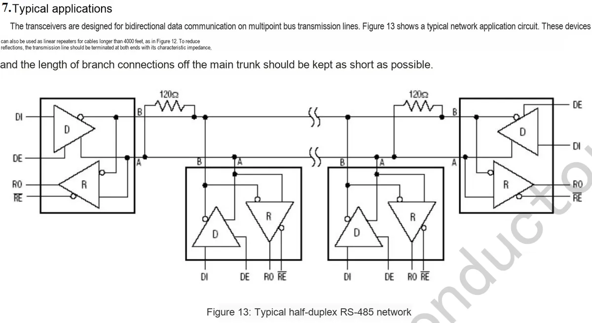
- 2.5 Reference Circuit
- 2.6 Chip Configuration
- 2.7 Communication Interfaces and Related Protocols
- 2.8 PCB Routing Precautions
- III. Instructions for Circuit Engineering and Module Usage
- 3.1 Circuit Source Engineering
- 3.2 Module Usage Instructions
- 3.3 Application Experiment
- IV. Drivers
- 5. BOM & Recommended Alternative Parts
- VI. Revision History
- VII. Relevant Materials
- 7.1 Chip Datasheet
- 7.2 Unique Icons for PCB Silk Screen
I. Module Introduction
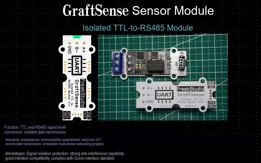
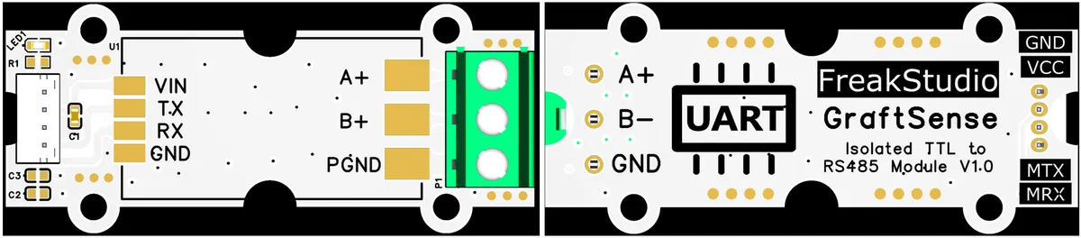
Isolated TTL to RS485 module is a communication interface module based on the JSM485ESA chip, integrating an isolated power supply and communication isolation IC to realize bidirectional conversion between TTL and RS485 levels with electrical isolation function. It is compatible with 3.3V/5V power supply, supports high-speed communication, and is suitable for scenarios with high anti-interference requirements such as industrial control and the Internet of Things, building a safe and reliable isolated communication bridge between TTL devices and RS485 devices.
- Compatible with
TTL/RS485standards, it can convertTTLsignals intoRS485signals, supporting half-duplex communication; - Compatible with 3.3V ~ 5V
TTLsignal levels, with overvoltage protection circuit on the power supply terminal; - Onboard integrated digital isolation enables signal isolation, featuring high reliability, strong anti-interference capability and low power consumption;
- Onboard
TVS(Transient Voltage Suppressor), which can effectively suppress surge voltage and transient spike voltage in the circuit, and is lightning protection and anti-static; - Onboard self-recovery fuses and protection diodes ensure stable current and voltage output, prevent overcurrent and overvoltage, and improve impact resistance.
- Onboard
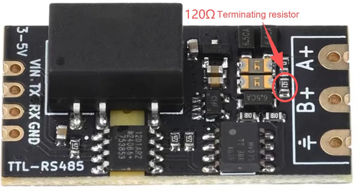
RS485output terminal with 120R resistor, which can be removed or retained as needed.
II. Introduction to Main Chips
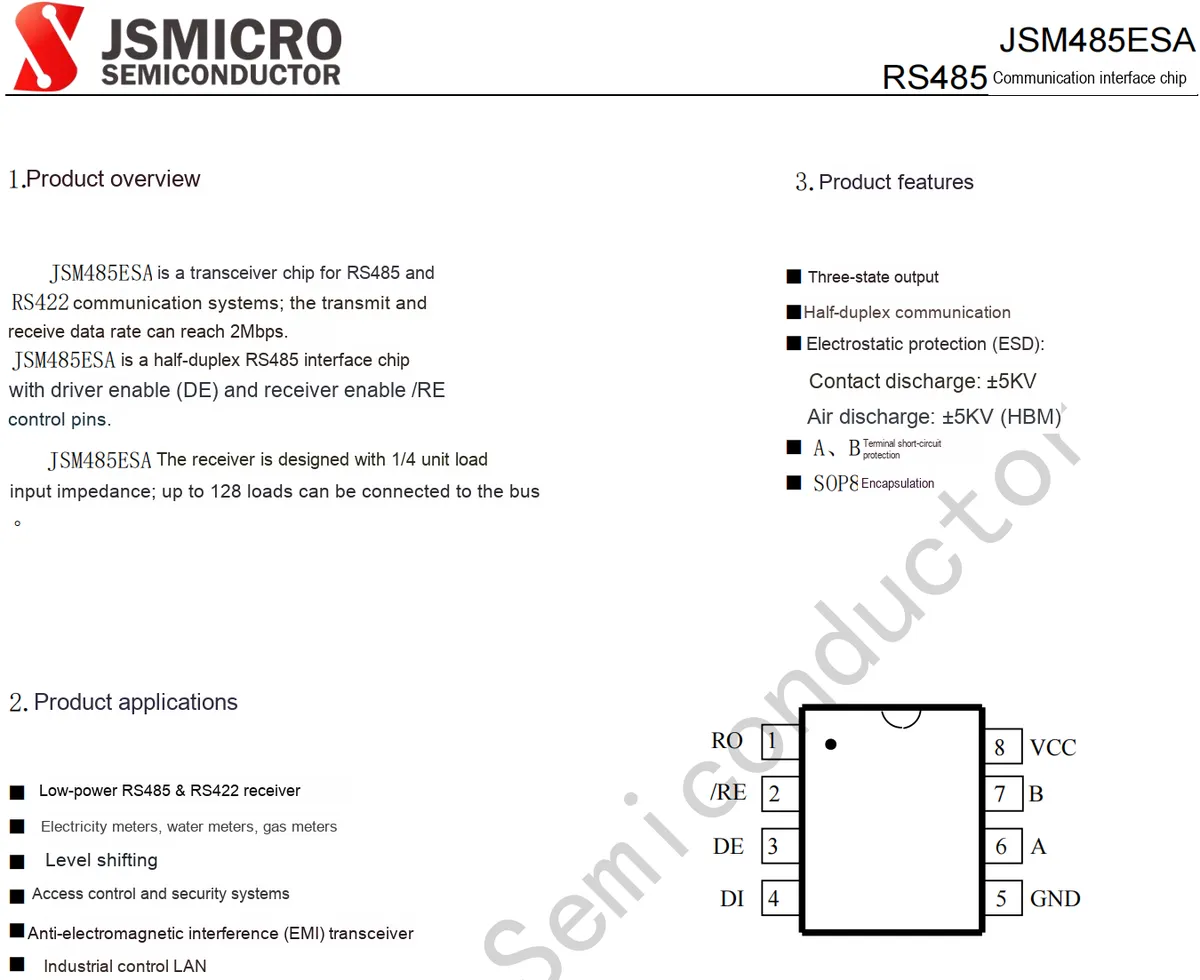
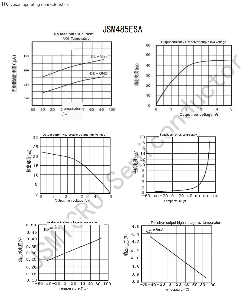
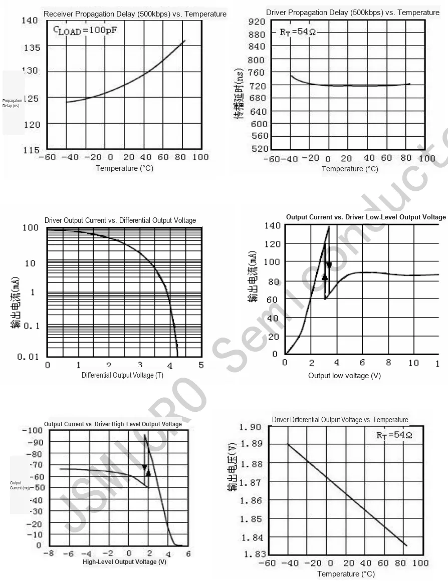
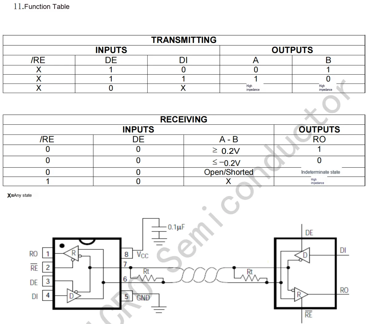
JSM485ESA is a half-duplex transceiver chip designed for RS485 and RS422 communication systems. It supports a data rate up to 2Mbps, and features control pins for driver enable (DE) and receiver enable (/RE). Its receiver adopts 1/4 unit load input impedance, allowing up to 28 loads on a single bus, and supports tri-state output. It offers ±5KV ESD protection (contact/air discharge) as well as short-circuit protection for pins A and B. Housed in an SOP8 package, this chip is suitable for low-power transceiving, electricity meters, access control systems, industrial control local area networks and other scenarios, making it a highly EMI-resistant RS485 interface chip.
2.1 Chip Overview
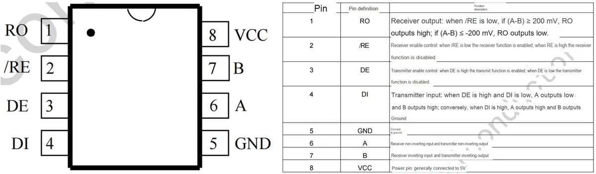
2.2 Pin Definition
2.3 Functional Block Diagram
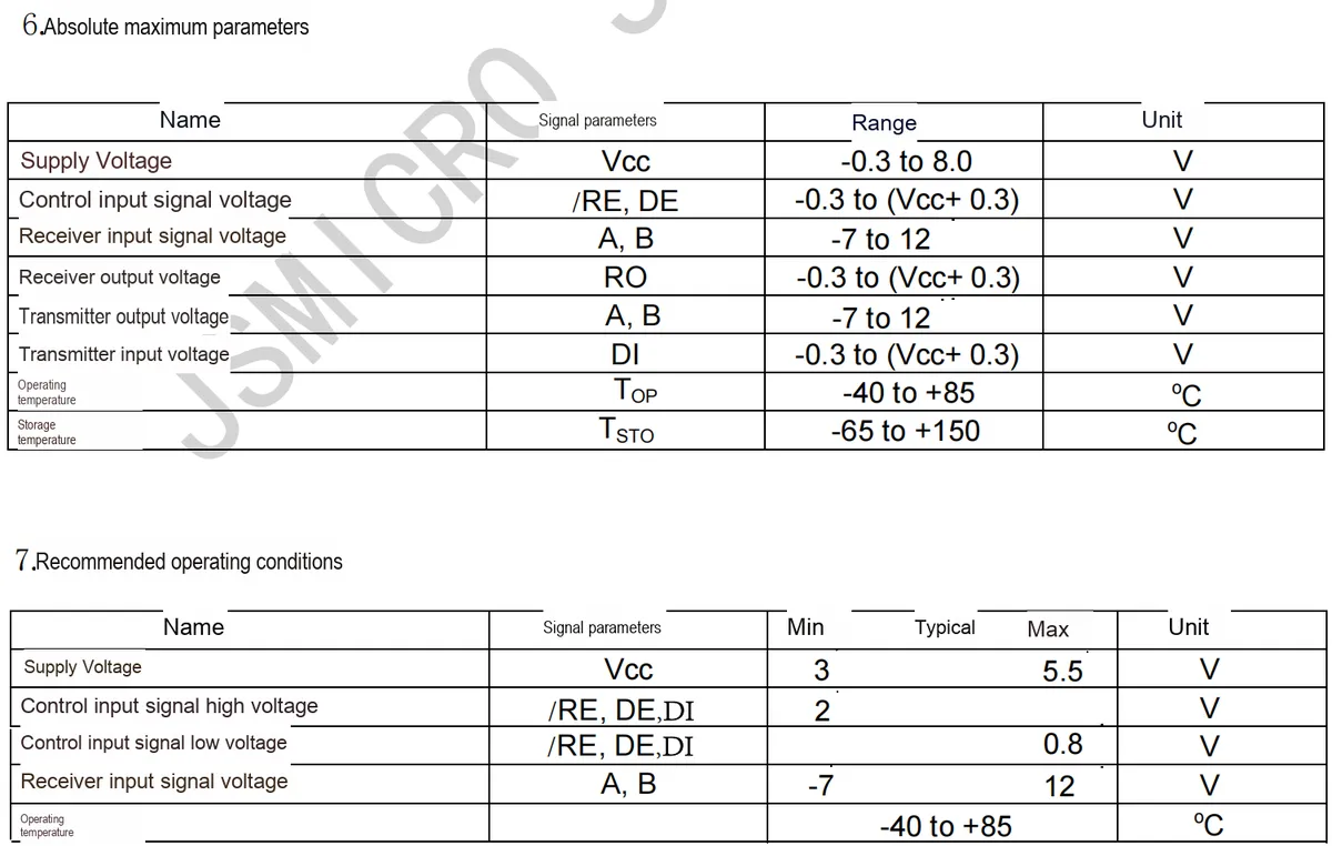
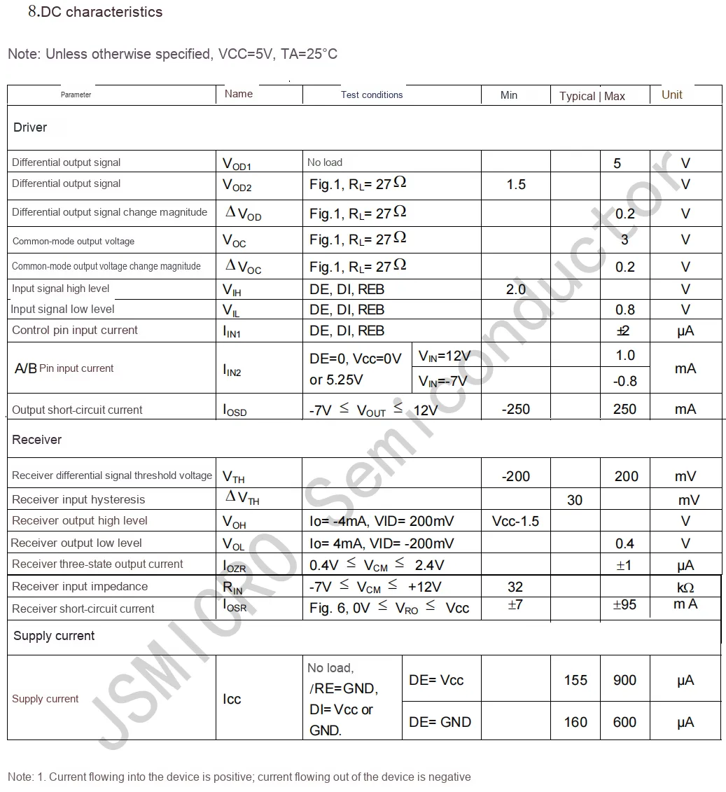
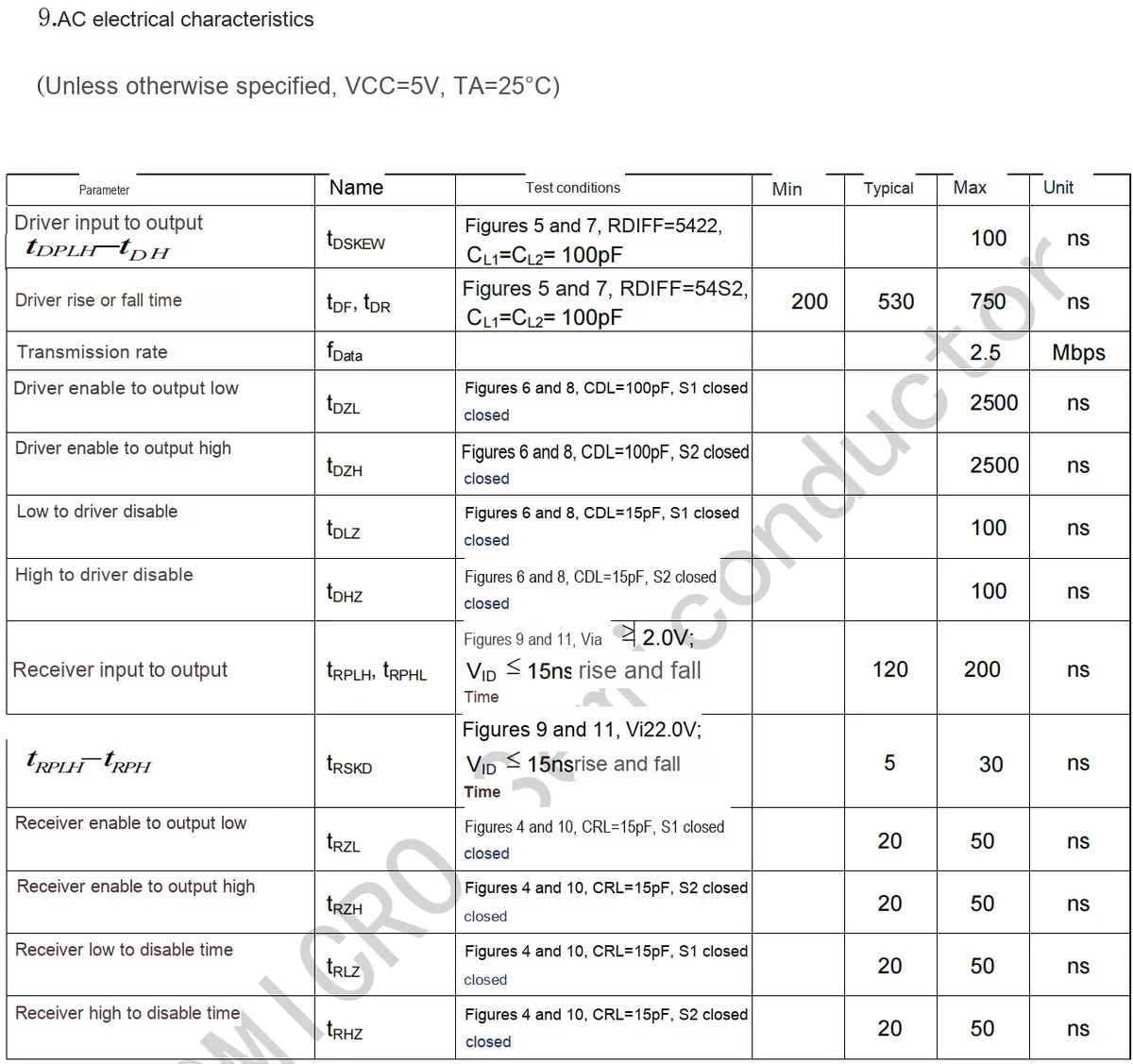
2.4 Performance Parameters
2.5 Reference Circuit
2.6 Chip Configuration
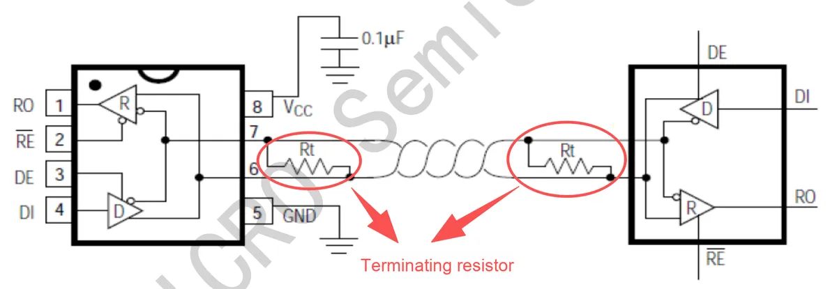
We can adjust the terminal resistor of the RS485 module on the board as required:
2.7 Communication Interfaces and Related Protocols
None.
2.8 PCB Routing Precautions
None.
III. Instructions for Circuit Engineering and Module Usage
3.1 Circuit Source Engineering
To obtain the circuit source project, please follow the official account [Freak Embedded]
3.2 Module Usage Instructions
3.2.1 Basic Instructions for Module Usage
The schematic diagram of this module is shown below:
SCH_Isolated TTL to RS485 Module_v1.0_2025-11-23.pdf 1.7 MB
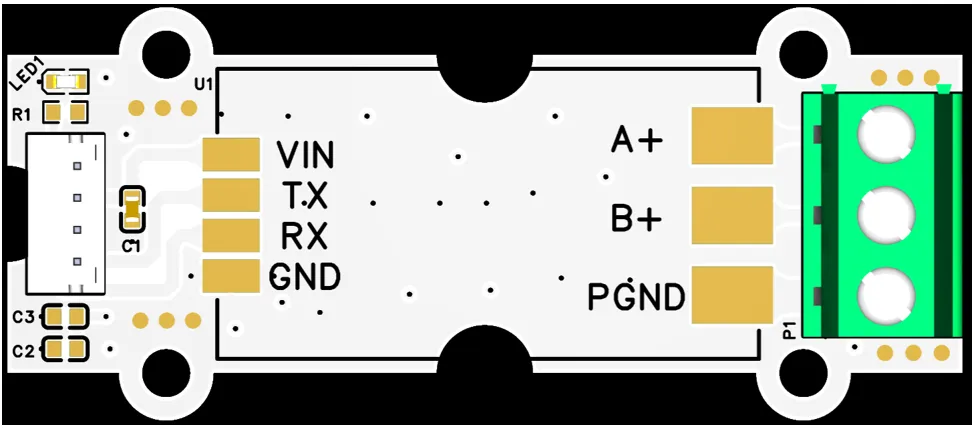
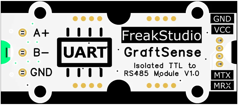
This module provides a UART interface: the MRX (corresponding to the UART MCU serial port RXD) is actually connected to the module's TXD pin, and the MTX (corresponding to the MCU serial port TX) is actually connected to the module's RXD pin;do not cross-connect them under any circumstances.
When we need to connect a computer to a RS485 module, a USB to 485 adapter is required:
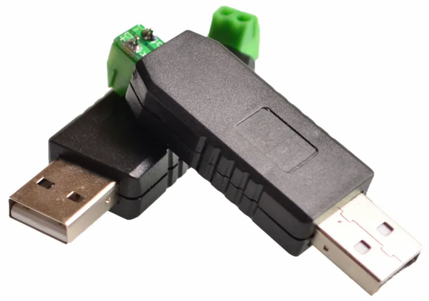
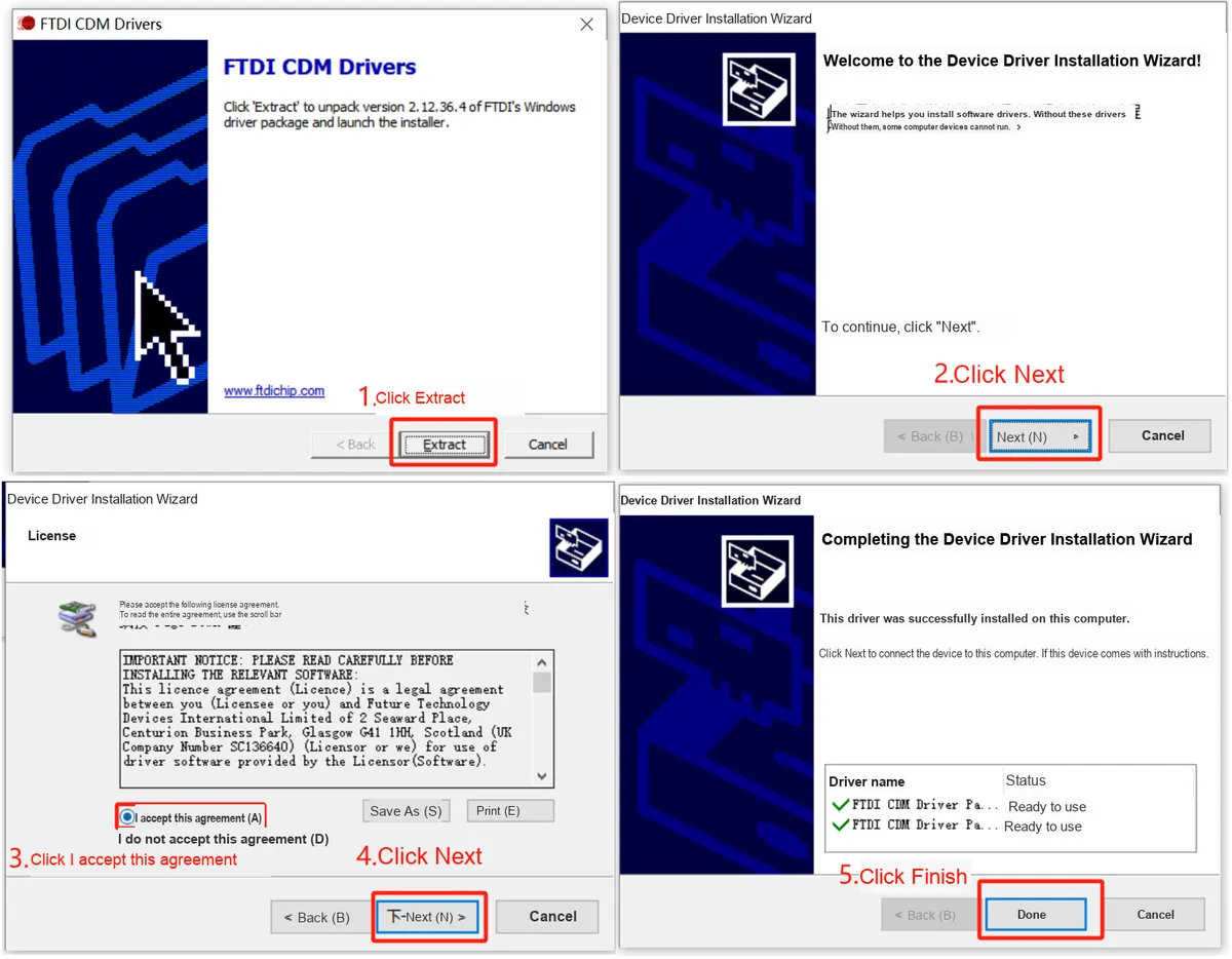
Common USB to 485 adapters use the FT232 chip, and we need to install the corresponding driver. In addition to being downloadable from FTDI 's official website: https://ftdichip.com/drivers/vcp-drivers/ .
Double-click the left mouse button and follow the steps below to install:
3.2.2 Basic Knowledge of RS485 Communication
RS-232 Communication Protocol has the following drawbacks, which make it difficult to be applied in long-distance and industrial scenarios:
- High signal level:
The signal level of RS-232is typically around ±12V, and may even reach ±15V; such a high level can easily damage the chips in the interface circuit. If connection to a low-voltageTTLcircuit (e. g., 5V or 3.3V) is required, a level conversion circuit must be used to protect the device and achieve signal matching - Low transmission rate:
The baud rate of RS-232is relatively low. Especially in asynchronous transmission scenarios, its maximum rate is only 20Kbps, which is far from meeting the demands of modern high-speed communication, particularly in applications requiring rapid data exchange. - Poor anti-interference performance:
RS-232adopts a single-ended signal transmission mode, where a signal loop is formed by one signal line and one common ground line; this structure is susceptible to common-mode interference, which degrades signal quality and results in weak anti-noise performance, a drawback that becomes particularly prominent during long-distance transmission. - Limited transmission distance: According to the standard specification
RS-232, the maximum transmission distance is 50 feet (approximately 15 meters). In practice, the transmission distance generally does not exceed 50 meters; beyond this distance, the signal will attenuate significantly, making it impossible to guarantee the reliability of communication.
Therefore, subsequent engineers developed the RS-485 Communication Protocol. Compared with the RS-232 interface, RS-485 has remarkable advantages in terms of transmission distance, anti-interference capability, multi-device communication and other aspects:
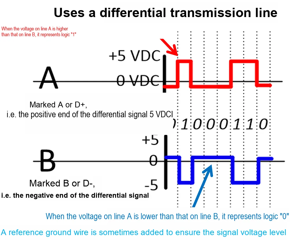
- Differential signal transmission:
RS-485uses two signal lines (AandB) to represent "0" and "1" through voltage difference; this differential transmission method can effectively resist electromagnetic interference and ensure stable communication in noisy environments - Multipoint communication:
RS-485allows multiple devices to be connected to the same bus, typically supporting 32 transmitters and 32 receivers, and even more devices can be connected via repeaters, which makesRS-485highly suitable for scenarios requiring interconnection of multiple devices - Long-distance transmission:
RS-485supports a maximum transmission distance of 1200 meters (approximately 4000 feet), and its transmission speed is inversely proportional to the distance; as the transmission distance decreases, the data transmission rate can be increased, reaching a maximum of 10 Mbps
Unlike RS-232 or TTL, RS-485 operates in half-duplex mode in most applications, meaning only one device can transmit data at a time while all other devices are in the receiving state; therefore, an additional protocol is required to coordinate communication between devices.
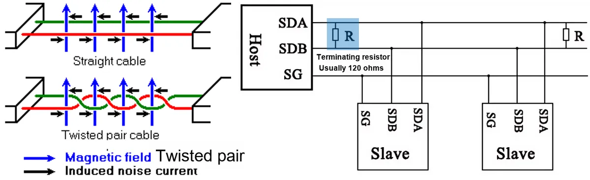
A typical RS-485 bus topology consists of multiple devices connected in series on a main trunk line; each device is equipped with an independent transmitter and receiver, and shares a pair of communication lines (A and B). We usually use twisted pair cables to reduce electromagnetic interference and noise. Meanwhile, for long-distance or high-speed transmission, terminal resistors (typically 120 ohms) are usually added at both ends of the bus to avoid signal reflection and interference.
In the RS-485 master-slave communication architecture, different devices can be divided into two roles:
- Master Device (
Master): responsible for controlling the entire communication process, initiating data requests, and sending commands and data to slave devices - Slave Devices (
Slaves): Each slave device has a unique deviceID(address), and it passively responds to the requests from the master device during communication; only when the master device sends a matching address to it will the slave device process data and send a response as needed.
The communication process can be summarized as follows:
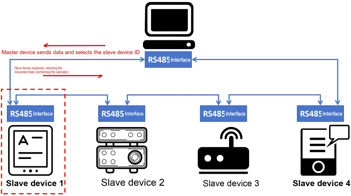
- Master device data transmission: The master device transmits data via the
RS-485bus, which includes the address of the target slave device (slaveID) and specific data; both lineA(+ signal) and lineB(- signal) are connected to all slave devices simultaneously - Slave device listening: All slave devices are listening to the data streams on lines
AandB, and checking the address information sent by the master device. - Slave device selection: When a slave device detects that the address in the transmitted data packet matches its own slave device
ID, it will receive the data packet and perform corresponding processing - Slave device response: If the Communication Protocol requires the slave device to return data (such as status information, sensor data, etc.), the slave device will send response data to the master device;
RS-485is generally half-duplex, which means only one device can transmit data at the same time, so the transmission of response data needs to be carried out according to a predetermined timing sequence
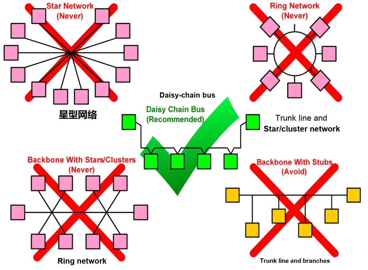
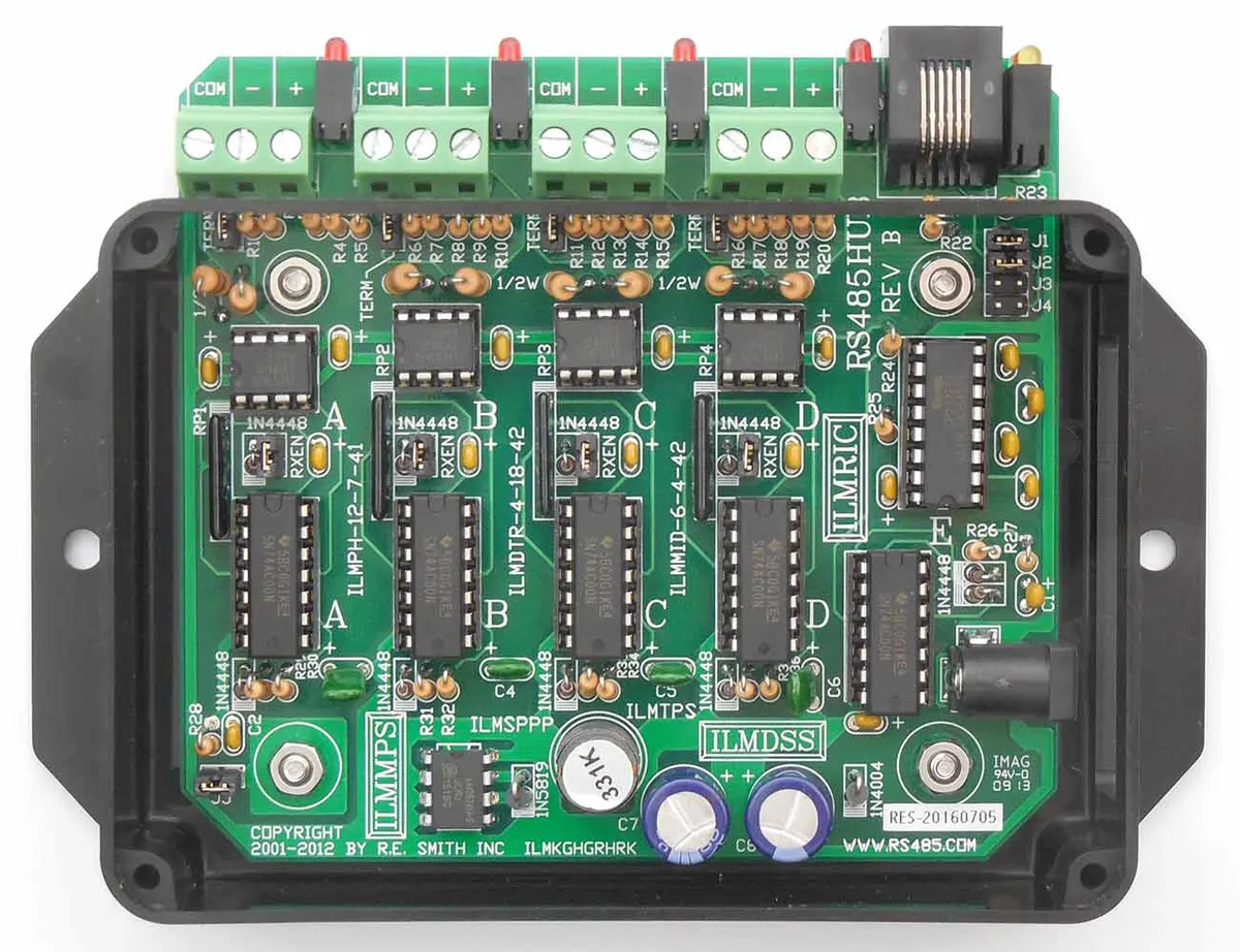
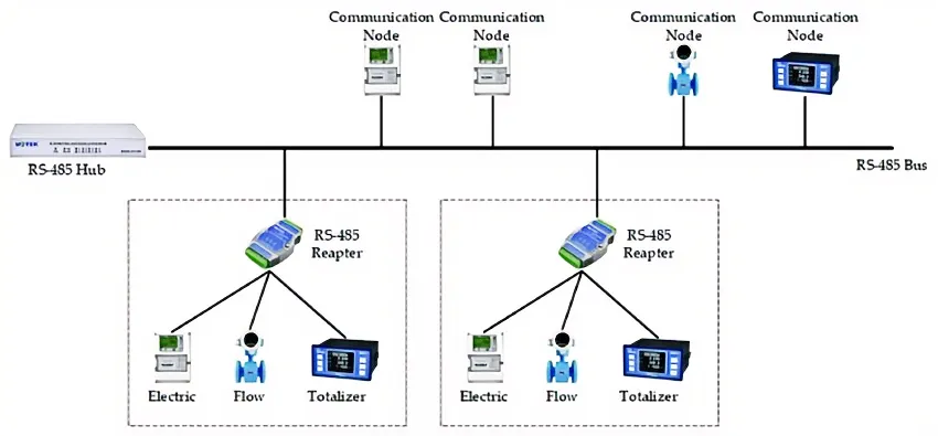
With the exception of the daisy-chain bus (which connects devices in series one after another to form a single-path communication link), other topologies are not recommended for use in RS-485 communication, as they will cause severe signal reflection and interference issues. If a topology such as a star topology must be used, it is mandatory to deploy RS-485 hubs or repeaters to avoid signal reflection and interference:
When using RS-485 communication, it is imperative to note that RS-485 signal lines and power lines must not be routed together, as power lines generate strong electromagnetic interference that will disrupt the signal lines transmitting data; meanwhile, RS-485 bus requires single-point grounding, meaning there shall be only one grounding point on the bus. If multiple grounding points occur, potential differences between ground wires will be caused, which further leads to common-mode interference and affects the stability of communication.
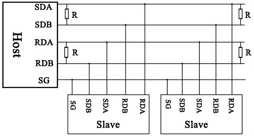
RS-485 communication can also achieve full-duplex data transmission, with TX and RX having separate dedicated lines for communication; however, in this mode, slave devices cannot communicate directly with each other, and all data transmission between them must be routed through the master device.
3.2.3 Communication Connection of RS485
TTL to RS485 interface conversion, point-to-point, half-duplex communication, applicable for interface conversion scenarios:
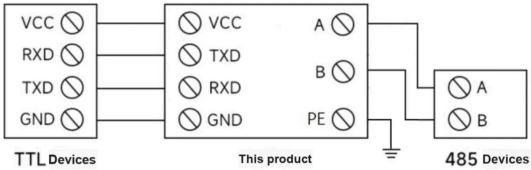
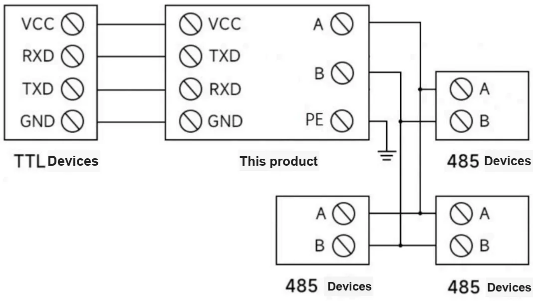
TTL to RS485 interface conversion, point-to-multipoint, half-duplex communication, suitable for expanding communication nodes:
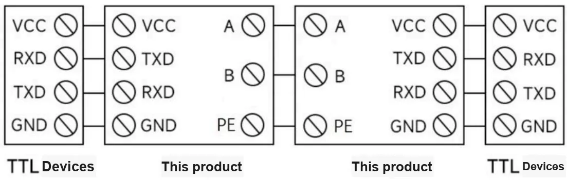
Through two sets of TTL and RS485 interface conversion, point-to-point, half-duplex communication, it is suitable for extending the communication distance of TTL:
3.3 Application Experiment
Here, we use the GraftPort-RP2040 development board for testing, and will based on an isolated TTL-to-RS485 module to communicate with the main controller via the UART interface.
Here, we first use the HY2.0-4P cable to connect the module to the GraftPort-RP2040 development board's UART1 interface. Meanwhile, you need to connect the isolated TTL to RS485 module 's RS485-A and RS485-B pins to the adapter' s T/R+ and T/R- pins, connect the GND of both devices, then connect the adapter to the computer via a USB port. The physical connection diagram is shown below:
The module connections are shown in the following table:
development board pins | Module Pins | Description |
Pin 8 |
|
|
Pin 9 |
|
|
In this hardware connection step, we use the RS485 adapter to interface with the XCOM software, and meanwhile realize communication with the microcontroller via the isolated TTL to RS485 module; the corresponding serial communication parameter configuration of the XCOM software is as follows:
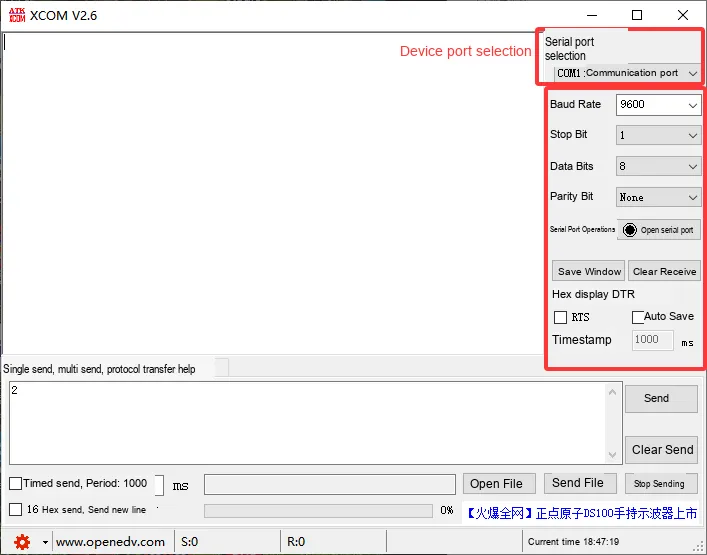
After completing the settings, we click Open Serial Port, and that's it.
Import UART 485 Loopback Test - MicroPython Driver Code
Next, copy the test code for verifying the function of the verification module below main.py into our project:
# Python env   : MicroPython v1.23.0
# -*- coding: utf-8 -*-
# @Time    : 2025/09/04 10:00
# @Author  : 侯钧瀚
# @File    : main.py
# @Description : 485 serial loopback test code

# ======================================== Import Modules =========================================

from machine import UART, Pin
import time

# ======================================== Global Variables ============================================

# Test message counter
count = 1

# ======================================== Functions ============================================

# ======================================== Custom Classes ============================================

# ======================================== Initialization ==========================================

# Power-on delay of 3 s
time.sleep(3)
print("FreakStudio: UART loopback test started. Sending data every 2 seconds...")

# Initialize UART1: TX=Pin8, RX=Pin9, baud rate 9600
uart = UART(1, baudrate=9600, tx=Pin(8), rx=Pin(9))

# ========================================  Main Program  ===========================================

try:
    while True:
        # Build test message with counter
        test_msg = f"Test message {count}: Hello, UART loopback!"
        print(f"\nSent: {test_msg}")

        # Send message
        uart.write(test_msg.encode('utf-8'))

        # Wait a short time to receive data
        time.sleep(0.1)

        # Read and print received data
        if uart.any():
            received = uart.read(uart.any()).decode('utf-8')
            print(f"Received: {received}")
        else:
            print("Received: No data (check connections)")

        # Increment counter and wait 2 seconds before the next send
        count += 1
        time.sleep(2)
except KeyboardInterrupt:
    print("\nTest stopped by user")
To flash the code, open a terminal and use the mpremote tool to connect to the main controller; the output is as follows:
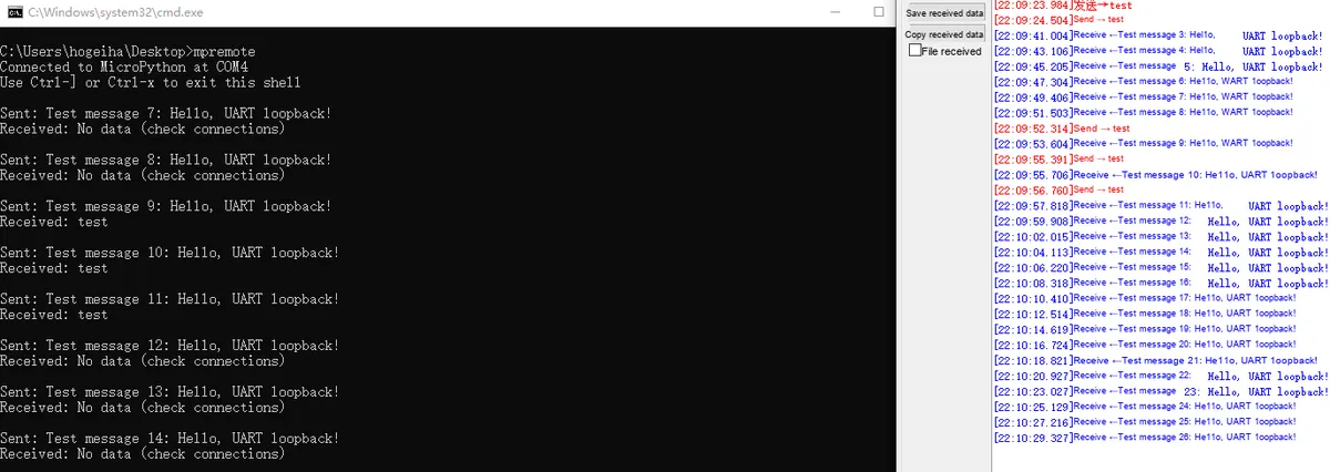
It can be seen that our module can normally complete the loopback test function of the serial port.
IV. Drivers
ttl_rs485_code.zip 8 KB
5. BOM & Recommended Alternative Parts
None.
VI. Revision History
Document Version | Revision Date | Modifier | Revised Content |
v1.0 | 2025-11-22 | Li Zisheng | Initialize Document The BOM sheet has not been finally checked, the driver has not been re-verified, and the 3.3 application experiment Not yet specified. |
v1.1 | 2025-12-29 | Li Zisheng | Added application experiments and production files |
v1.2 | 2025-12-31 | Sin Ruili | Create an open version of the document based on the internal document version v1.1. |
VII. Relevant Materials
7.1 Chip Datasheet
C5381783_RS-485-RS-422 Chip_JSM485ESA_Datasheet_WJ974414.PDF 2.3 MB
7.2 Unique Icons for PCB Silk Screen