Contents
- I. Module Introduction
- II. Introduction to Main Chips
- 2.1 Chip Overview
- 2.2 Pin Definition
- 2.3 Functional Block Diagram
- 2.4 Performance Parameters
- 2.5 Reference Circuit
- 2.6 Chip Configuration
- 2.7 Communication Interfaces and Related Protocols
- 2.8 PCB Routing Precautions
- III. Circuit Engineering
- 3.1 Circuit Source Engineering
- 3.2 Module Usage Instructions
- 3.3 Application Experiment
- IV. Drivers
- 5. BOM & Recommended Alternative Parts
- VI. Revision History
- VII. Relevant Materials
- 7.1 Chip Datasheet
- 7.2 PCB Silkscreen Specific Icons
I. Module Introduction
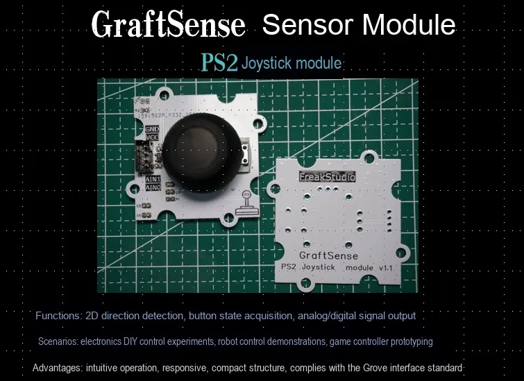
PS2 Joystick Module is a dual-axis joystick module based on the principle of mechanical potentiometers, which is commonly used for direction input, angle control and human-computer interaction. This joystick adopts a through-hole mounting structure, which facilitates soldering and fixation on the circuit board. With a sturdy and reliable overall structure, it is suitable for long-time operation.
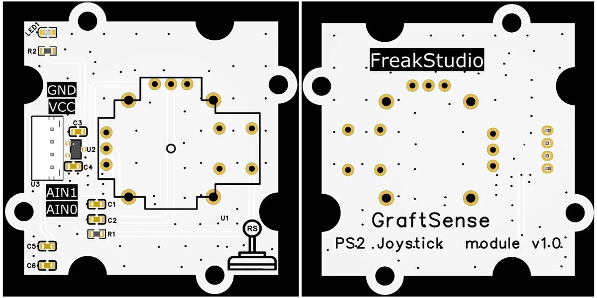
PS2 Joystick Module supports 5V power supply, which is converted to 3.3V via a DC-DC circuit to power the joystick core; the joystick has built-in X and Y direction potentiometers, AIN0 and AIN1 output analog voltage signals of these two directions respectively. External devices can detect the 2D position offset of the joystick by reading these two voltages. The module is also equipped with auxiliary circuits such as indicator lights. This module can be widely used in interactive scenarios including remote control equipment, robot control, game controllers, menu navigation, intelligent vehicles, etc. , and is a stable and reliable human-machine input device.
II. Introduction to Main Chips
Adopts the rocker potentiometer switch 10K 103 530.
2.1 Chip Overview
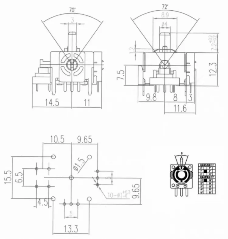
Joystick Potentiometer Switch 10K (marked as 103) 530 with :
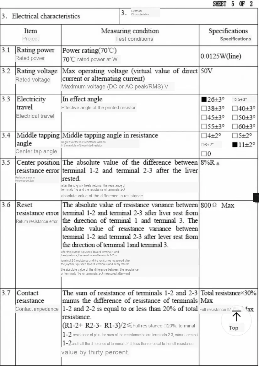
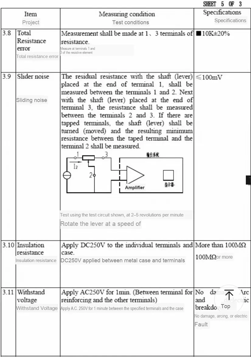
- Electrical Characteristics: Total resistance: 10K±20%, rated power at 70℃: 0.0125W, rated voltage: 50V, sliding noise ≤ 100mV, insulation resistance > 100MΩ, withstanding AC250V voltage for 1 minute without damage is supported;
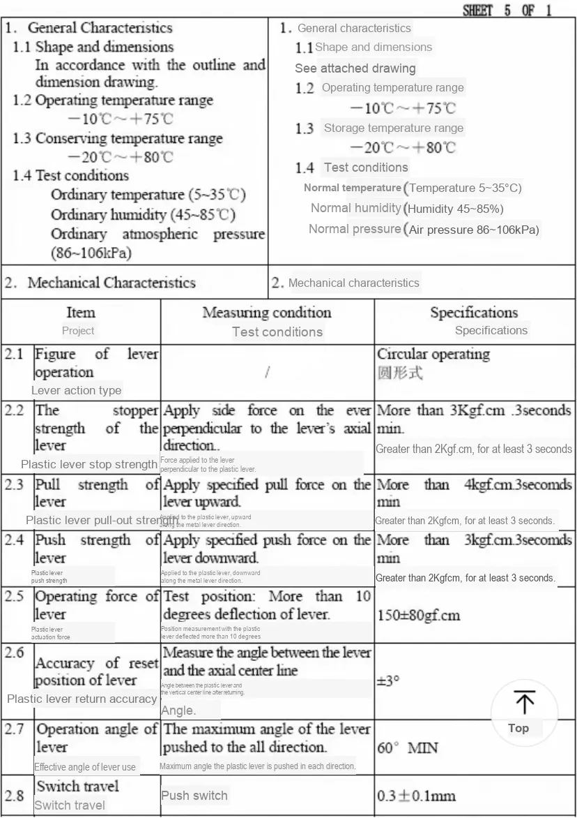
- Mechanical Characteristics: The operating form of the handle is circular, the effective operating angle is ≥60°, the switch travel is 0.3±0.1mm, the handle actuation force is 150±80gf.cm, and the reset accuracy is ±3°;
- Environmental Characteristics: Operating temperature: -10℃ to + 75℃, storage temperature: -20℃ to + 80℃. This potentiometer is compatible with scenarios such as Arduino, supports resistance adjustment, and features reliable mechanical strength and electrical performance.
The main functions are as follows:
- Dual-axis analog input: It provides analog voltage outputs in two directions, X and Y, which correspond to the resistance voltage division of the potentiometer respectively, facilitating the detection of angle changes.
- Push switch function: In addition to dual-axis control, the joystick can be pressed down to trigger an independent key signal, adding an extra dimension of input.
- Automatic centering: Built-in return spring enables the lever to automatically return to the neutral position after being released, facilitating the establishment of a zero-point reference.
2.2 Pin Definition
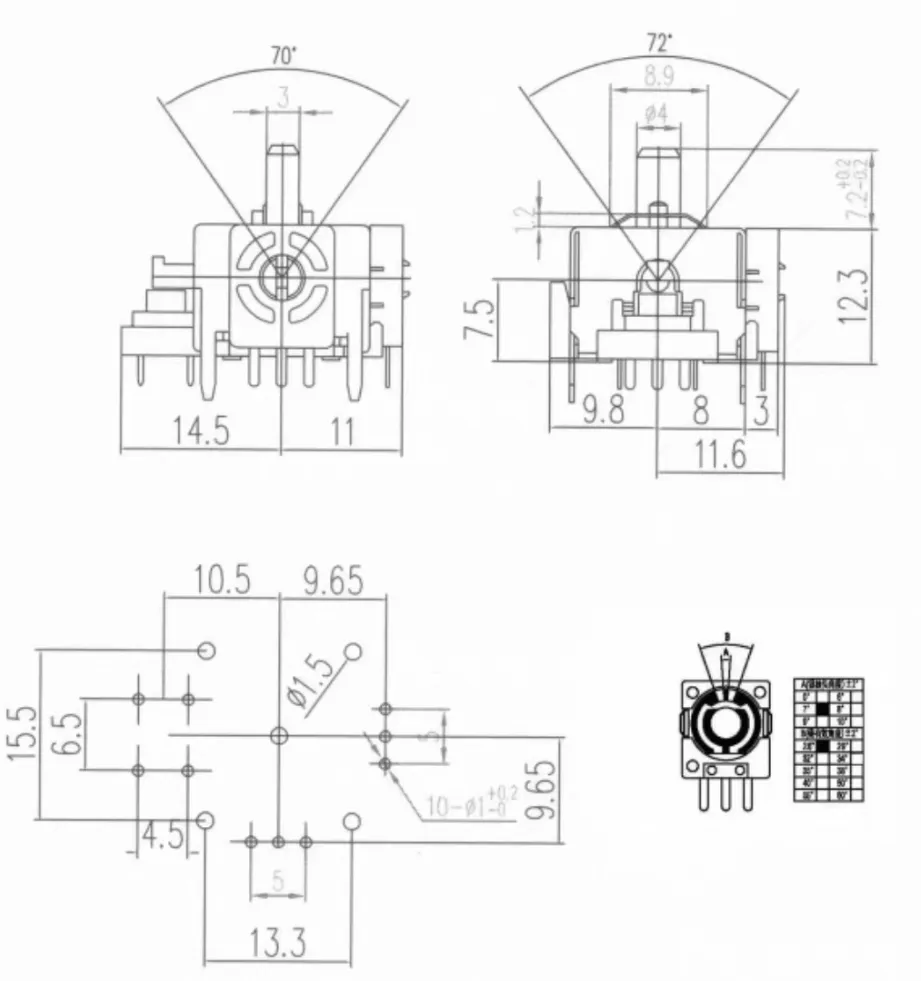
This joystick potentiometer is equipped with two sets of potentiometer pins for the X-axis and Y-axis (each set includes two fixed resistor terminals and one sliding terminal that moves with the joystick to output variable resistance signals), as well as a push switch pin. When the joystick is tilted in the X or Y direction, the sliding terminal of the corresponding axis potentiometer will change its resistance relative to the fixed terminals, thereby outputting an analog signal; pressing the joystick can realize on-off control through the switch pin, which facilitates position or switch signal acquisition in coordination with controllers such as Arduino.
2.3 Functional Block Diagram
None.
2.4 Performance Parameters
2.5 Reference Circuit
None.
2.6 Chip Configuration
None
2.7 Communication Interfaces and Related Protocols
None.
2.8 PCB Routing Precautions
None.
III. Circuit Engineering
3.1 Circuit Source Engineering
To obtain the circuit source project, please follow the official account [Freak Embedded]
3.2 Module Usage Instructions
The schematic diagram of this module is shown below:
SCH_Schematic1_PS2 Joystick Module_v1.0_2025-09-24.pdf 3.0 MB
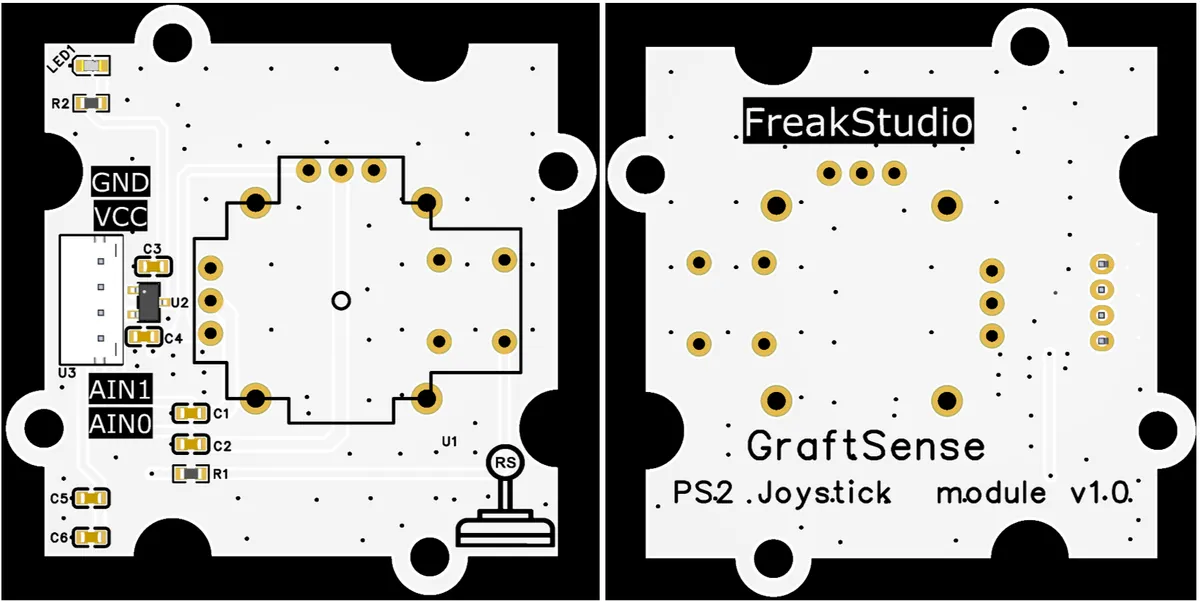
This module provides two analog output interfaces (AIN0, AIN1):
- The two analog output interfaces of this module
AIN0andAIN1correspond to the analog signal outputs of the joystick X-axis (VRX) and Y-axis (VRY) respectively: - When the joystick is swung in the horizontal (X-axis) and vertical (Y-axis) directions, the X-axis and Y-axis potentiometers output variable analog voltages. After being processed by the module circuit, the analog quantity corresponding to the X-axis position is output via the
AIN0interface, and the analog quantity corresponding to the Y-axis position is output via theAIN1interface, for collection by external devices (such as a microcontroller) to obtain the joystick action information.
The module is equipped with an onboard 5V-to-3V3 power supply chip, which only requires a direct 5V power input. AIN0 and AIN1 have a maximum output voltage of no more than 3.3V.
3.3 Application Experiment
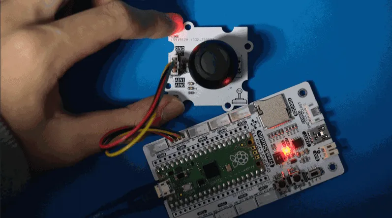
Here, we use the Raspberry Pi Pico core board for testing, and the connection between the PS2 joystick module and the Raspberry Pi Pico core board is shown in the following table:
development board pins | Module Pins | Description |
Pin 28 |
| Connect the ADC input pin of the MCU |
Pin 27 |
| Connect the ADC input pin of the MCU |
Here, we need to search for the relevant driver packages on uPyPI: https://upypi.net/zh/
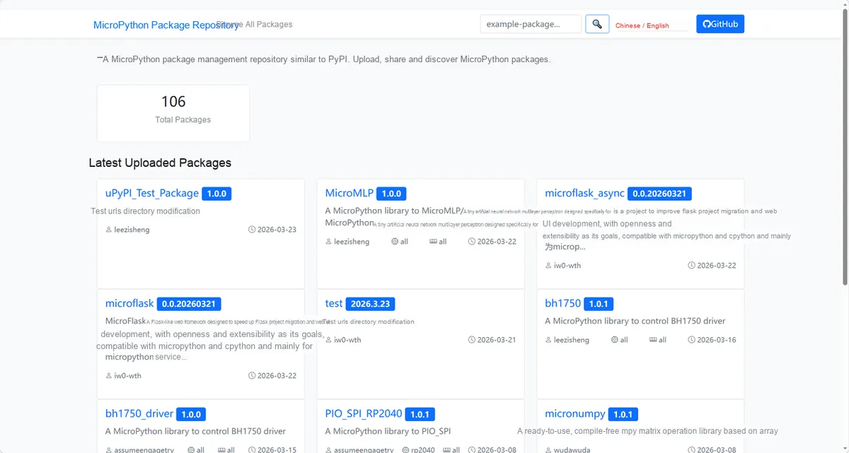
Enter ps2_joystick_driver to search, and the following will be displayed:
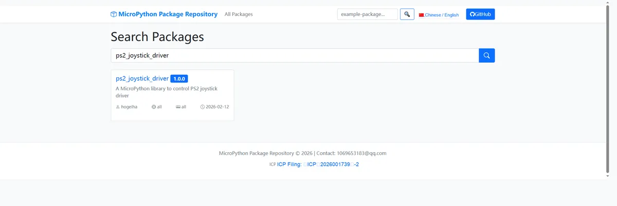
Click to copy the local installation command:
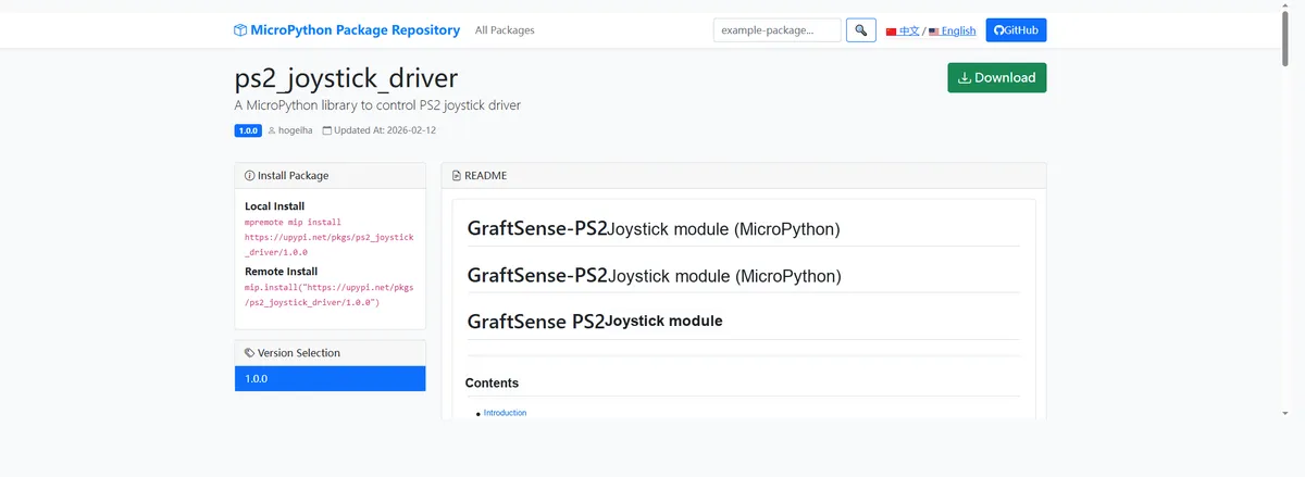
Here, we can import the module driver library code via the mip tool. Below are the usage commands for the mpremote tool:
mpremote mip install github:FreakStudioCN/GraftSense-Drivers-MicroPython/input/ps2_joystick_driverAfter importing the PS2 joystick module - MicroPython driver code, copy the following main.py code into our project:
# Python env   : MicroPython v1.23.0
# -*- coding: utf-8 -*-
# @Time    : 2024/8/27 10:02 PM
# @Author  : Li Qingshui
# @File    : main.py
# @Description : ADC experiment, read the voltages at both ends of the joystick

# ======================================== Import Modules ========================================

# Import time-related modules
import time
# Import the joystick driver module
from joystick import Joystick

# ======================================== Global Variables ============================================

# ======================================== Functions ============================================

# ======================================== Custom Classes ============================================

# ======================================== Initialization ==========================================

# Delay 3 s to wait for the device to finish powering up
time.sleep(3)
# Print debug information
print("FreakStudio : reading the voltage value of Joystick experiment")

# Create a joystick instance, using ADC0-GP27 and ADC1-GP28 as the Y axis and X axis
joystick = Joystick(vrx_pin=28, vry_pin=27, freq=10)

# ========================================  Main Program  ===========================================

# Start joystick data collection
joystick.start()
# Print joystick data
try:
    while True:
        x_val, y_val, sw_val = joystick.get_values()
        print("Joystick values: X = {:.2f}, Y = {:.2f}, Switch = {}".format(x_val, y_val, sw_val))
        time.sleep(0.2)
except KeyboardInterrupt:
    print("Data collection completed")
finally:
    joystick.stop()
Burn the code, connect to the terminal, and the output is as follows:
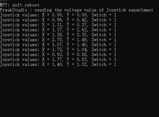
It can be seen that as we move the joystick, the X and Y values on the corresponding terminal have changed:
IV. Drivers
ps2_joystick_driver.zip 10 KB
5. BOM & Recommended Alternative Parts
None.
VI. Revision History
Document Version | Revision Date | Modifier | Revised Content |
v1.0 | 2025-09-04 | ben0i0d | Initialize Document |
v1.1 | 2025-09-24 | Li Zisheng | Added 2.8 PCB routing precautions Revised Section 3, Instructions for Circuit Source Project and Module Usage, and added a secondary heading: 3.1 Circuit Source Engineering, 3.2 Module Usage Instructions, 3.3 Application Experiments Modified the naming standard for the project imported in the 3.1 Circuit Source project The BOM sheet has not been finally checked, the driver has not been re-verified, and the 3.3 application experiment Not yet specified. |
v1.2 | 2025-12-29 | Li Zisheng | Added application experiments and production files |
v1.3 | 2025-12-31 | Sin Ruili | Create an open version of the document based on the internal document version v1.2. |
v1.4 | 2026-03-29 | Sin Ruili | Modified the application experiment section. |
VII. Relevant Materials
7.1 Chip Datasheet
Joystick Potentiometer Switch 10K 103 530 with Cap Datasheet.pdf 7.0 MB
7.2 PCB Silkscreen Specific Icons