Contents
- I. Module Introduction
- II. Introduction to Major Chips
- 2.1 Chip Overview
- 2.2 Pin Definition
- 2.3 Functional Block Diagram
- 2.4 Performance Parameters
- 2.5 Reference Circuit
- 2.6 Chip Configuration
- 2.7 Communication Interfaces and Related Protocols
- 2.8 PCB Routing Precautions
- III. Circuit Engineering
- 3.1 Circuit Source Engineering
- 3.2 Module Usage Instructions
- 3.3 Application Experiment
- 4. Drivers
- 5. BOM & Recommended Alternative Parts
- VI. Revision History
- VII. Relevant Materials
- 7.1 Chip Datasheet
- 7.2 PCB Silkscreen Specific Icons
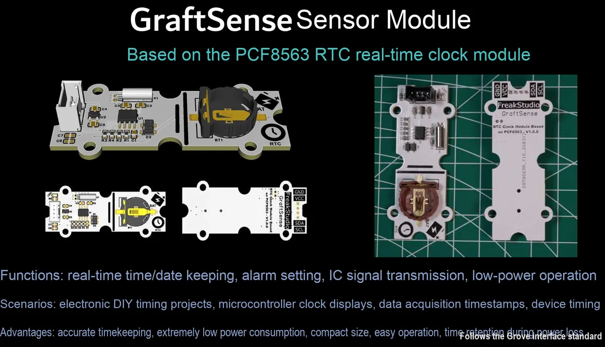
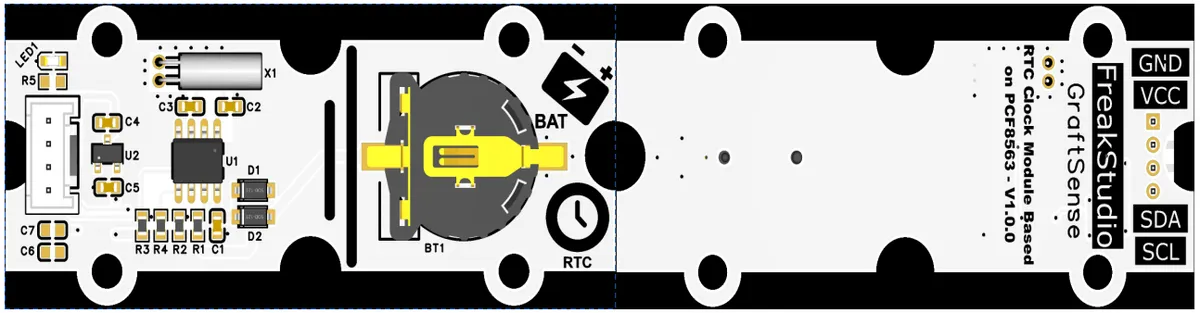
I. Module Introduction
RTC real-time clock module based on PCF8563, which adopts the PCF8563 chip solution, supports I²C interface communication, has a built-in 32.768kHz crystal oscillator circuit, features low-power timing, alarm interrupt and programmable clock output functions, is equipped with a 5V to 3.3V DC-DC power supply circuit, power filtering and indicator circuit, and supports backup power supply via CR series button batteries. It can provide stable and reliable real-time clock and timing functions for systems, and is suitable for scenarios requiring a time reference such as consumer electronics, smart homes, and industrial timing.
II. Introduction to Major Chips
PCF8563 is a low-power I²C interface real-time clock (RTC) chip with a built-in 32.768kHz crystal oscillator drive circuit, supporting alarm interrupt and programmable clock output, featuring wide-voltage power supply and battery backup functions, which can provide a stable time reference and timing capabilities.
2.1 Chip Overview
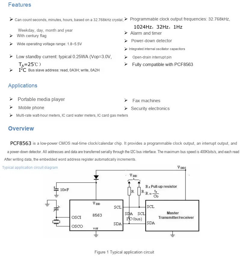
PCF8563 is a low-power CMOS real-time clock/calendar chip that features an I²C interface (read address 0A3H, write address 0A2H), supports a wide 1.8~5.5V power supply voltage range, and integrates an oscillation capacitor and power failure detection. It can provide second/minute/hour/day/month/year timing, alarm/timer functions, and a programmable clock output ranging from 32.768kHz to 1Hz, with a sleep current as low as 0.25μA, making it suitable for applications such as portable devices and smart meters.
2.2 Pin Definition
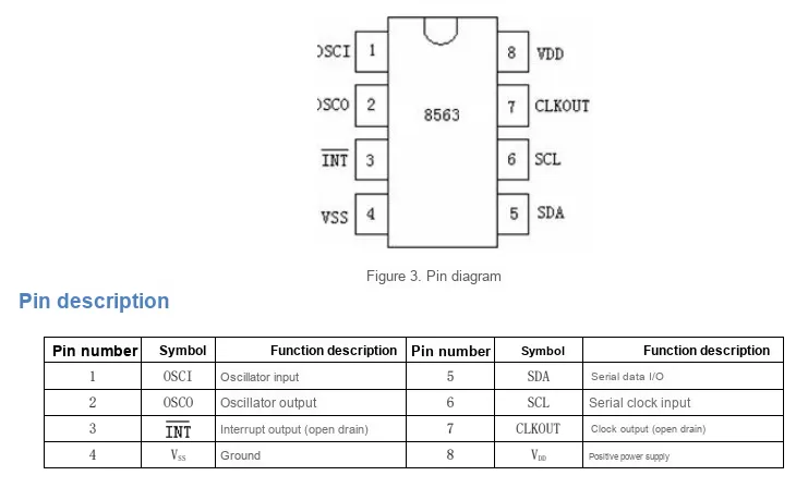
PCF8563 comes in an 8-pin package, and its core pins include 32.768kHz crystal oscillator input/output (OSCI / OSCO), I²C communication (SDA / SCL), power supply (VDD / VSS), open-drain interrupt output (INT) and programmable clock output (CLKOUT). With a concise and clear pin definition, it facilitates the implementation of low-power real-time clock and timing functions.
2.3 Functional Block Diagram
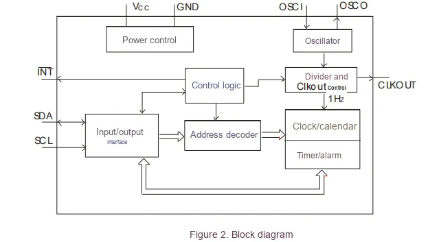
PCF8563 is a low-power real-time clock (RTC) chip that uses a 32.768kHz crystal oscillator as the reference clock. After frequency division, it drives the clock/calendar register set to realize automatic timing of seconds, minutes, hours, dates, months and years as well as leap year correction; its built-in timer/alarm module can trigger an interrupt, and it also supports programmable clock output ranging from 32.768kHz to 1Hz.The power management module supports wide-voltage power supply and battery backup, I²C interface is responsible for communicating with the main control to complete operations such as time reading/writing and function configuration. With a simple and efficient overall architecture, it is suitable for various low-power scenarios that require a time reference.
2.4 Performance Parameters
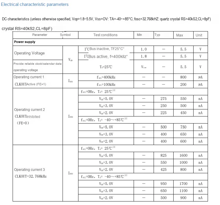
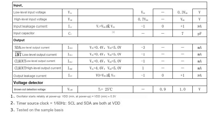
PCF8563 features a wide voltage supply capability of 1.8V to 5.5V; when CLKOUT is disabled, its typical sleep current is only 225~275nA, and the maximum operating current during I²C communication does not exceed 800μA. Its input level is compatible with the range of 0.3 VDD to 0.7 VDD, and the open-drain output pins (INT / CLKOUT / SDA) deliver reliable driving capability. Meanwhile, it has a built-in power failure detection circuit (typical threshold: 0.9V), and its overall electrical characteristics balance low power consumption and wide operating condition adaptability, making it ideal for battery-powered portable and IoT devices.
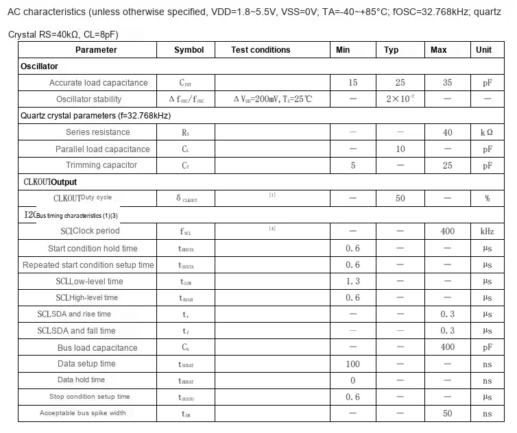

PCF8563 boasts excellent AC characteristics: its oscillator integrates a built-in load capacitance ranging from 15pF to 35pF, delivering a frequency stability of 2×10⁻⁷;CLKOUT output features a 50% duty cycle;I²C bus supports a maximum clock rate of 400kHz, with strictly defined parameters including START / STOP timing, SCL high and low level durations, data setup/hold times, the bus supports a maximum load capacitance of 400pF, and requires the access interval between two consecutive START conditions to be less than 1 second, enabling stable high-speed, reliable communication and clock output.
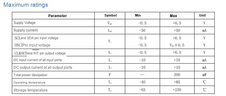
PCF8563 features a wide range of maximum ratings: the power supply voltage can withstand -0.5V to + 6.5V, the power supply current is limited to ±50mA, the input/output voltage of each pin is compatible with -0.5V to + 6.5V (the OSCI pin ranges from -0.5V to VDD + 0.5V), the input/output DC current is limited to ±10mA, and the total power dissipation does not exceed 300mW;It features an operating temperature range of -40℃ to + 85℃ and a storage temperature range of up to -65℃ to + 150℃. With strong resistance to overvoltage, overcurrent and temperature tolerance, it can adapt to harsh industrial and outdoor environments.
2.5 Reference Circuit
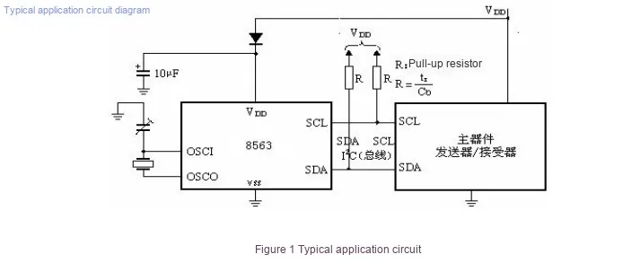
PCF8563 has a typical application circuit that is simple and efficient: The VDD pin is connected to the main power supply in series with a diode and a 10μF decoupling capacitor, and cooperates with a button battery to realize timekeeping continuation after power failure;the OSCI / OSCO pins are externally connected to a 32.768kHz crystal oscillator and a trimming capacitor to provide a stable clock reference;the SCL / SDA pins need to be externally connected to pull-up resistors before being connected to the main control I²C bus. The resistance of the pull-up resistor can be calculated according to the bus load capacitance (R = tr / Cb), and the overall circuit can stably implement the low-power real-time clock function.
2.6 Chip Configuration
None.
2.7 Communication Interfaces and Related Protocols
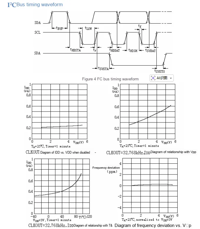
PCF8563's I²C bus strictly follows standard timing, including complete phases such as START/STOP and data setup/hold, and supports a maximum communication rate of 400kHz; it features excellent power consumption characteristics: when CLKOUT is disabled, the operating current is only approximately 0.25μA with negligible variation against voltage; when CLKOUT is enabled, the current rises gently as voltage increases and also grows with rising temperature; the frequency deviation remains stable within ±1ppm across the full voltage range, meaning the clock accuracy is barely affected by voltage fluctuations, delivering a balanced combination of low power consumption and high stability.
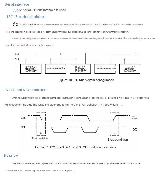
PCF8563 adopts the I²C serial bus interface, which communicates via two lines: SDA (Serial Data) and SCL (Serial Clock), both of which require an external pull-up resistor connected to the positive power supply; the bus follows a master-slave architecture where the master initiates communication, and data is only transmitted when the bus is idle: the START condition is defined by a falling edge on SDA while SCL is at high level, and the STOP condition is defined by a rising edge on SDA while SCL is at high level; each bit of data remains stable when SCL is at high level to ensure reliable transmission. The overall protocol is concise and universal, making it easy to connect to various master controllers.
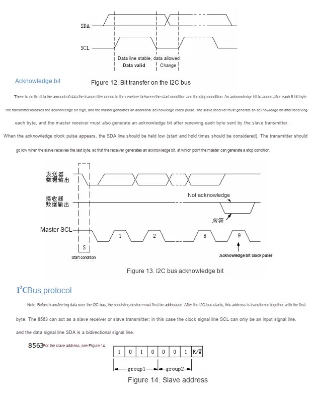
PCF8563 I²C communication follows a complete acknowledge mechanism: after every 8 bits of data are transmitted, the master generates the 9th clock pulse for acknowledgment, and the receiver must pull the SDA low at this time to indicate an acknowledgment (ACK), while pulling it high indicates a non-acknowledgment (NACK); before communication, a 7-bit slave address (fixed as 1010001) + read/write bit (R / W) must be sent first, and the chip will only respond after the address matches;SCL is a unidirectional input, SDA is a bidirectional data pin, the overall protocol is rigorous and reliable, and can stably realize multi-byte read and write.
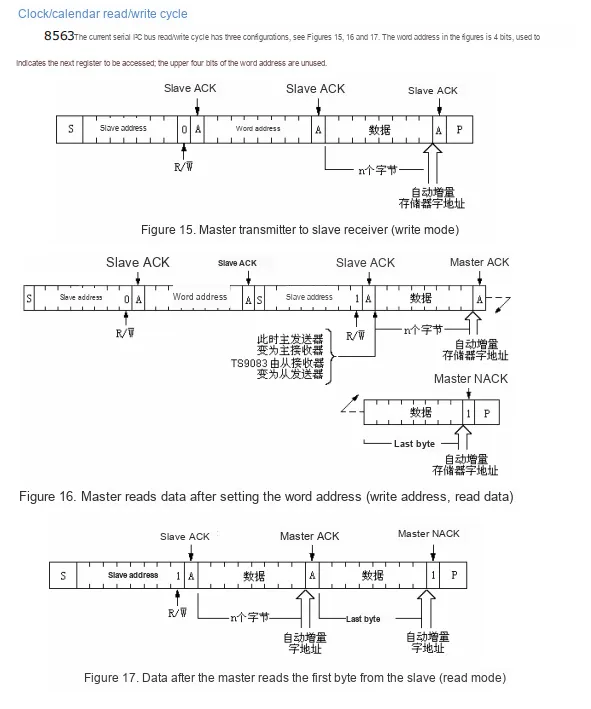
PCF8563 I²C read/write cycle supports three modes:
- Write mode: The master first sends the slave address (with the write bit) plus the register word address, then consecutively writes multi-byte data, with the word address automatically incrementing.
- Write-Read Mode: First send the word address to set the pointer, then repeat
STARTand send the slave address (read bit); the chip outputs data starting from the current address, with the word address automatically incrementing. - Direct Read Mode: After the master sends the slave address (with the read bit set), the chip outputs data directly, with the word address automatically incrementing, and the operation finally terminates with a combination of a NACK (
NACK) plus aSTOPcondition.
2.8 PCB Routing Precautions
None.
III. Circuit Engineering
3.1 Circuit Source Engineering
To obtain the circuit source project, please follow the official account [Freak Embedded].
3.2 Module Usage Instructions
The schematic diagram of this module is shown below:
SCH_PCF8563-Based RTC Real-Time Clock Module-V1.0.0_2026-03-26.pdf 2.2 MB
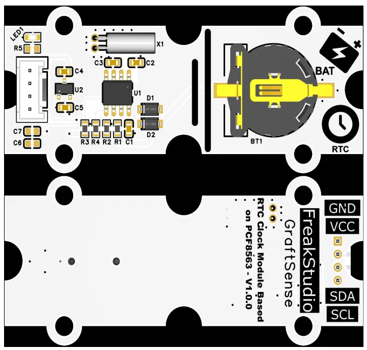
This module provides an IIC communication interface: it supports standard/fast I²C communication rates up to 400kHz, with a fixed slave address of 0x51 (read at 0xA3 / write at 0xA2). Built with a level adaptation circuit, it is compatible with 3.3V/5V host controller levels, and can stably implement read and write operations for real-time clock, alarm and timing functions. Meanwhile, it has a built-in CR1220 battery holder, which is suitable for scenarios requiring a precise time reference such as consumer electronics, smart home, and industrial timing, providing the system with reliable low-power time perception and interaction capabilities.
3.3 Application Experiment
Here, we use the GraftPort-RP2040 development board for testing. The PCF8563-based RTC real-time clock module uses the I2C interface to communicate with the main controller.
Here, we first use the HY2.0-4P cable to connect the module to the GraftPort-RP2040 development board's I2C0 interface:
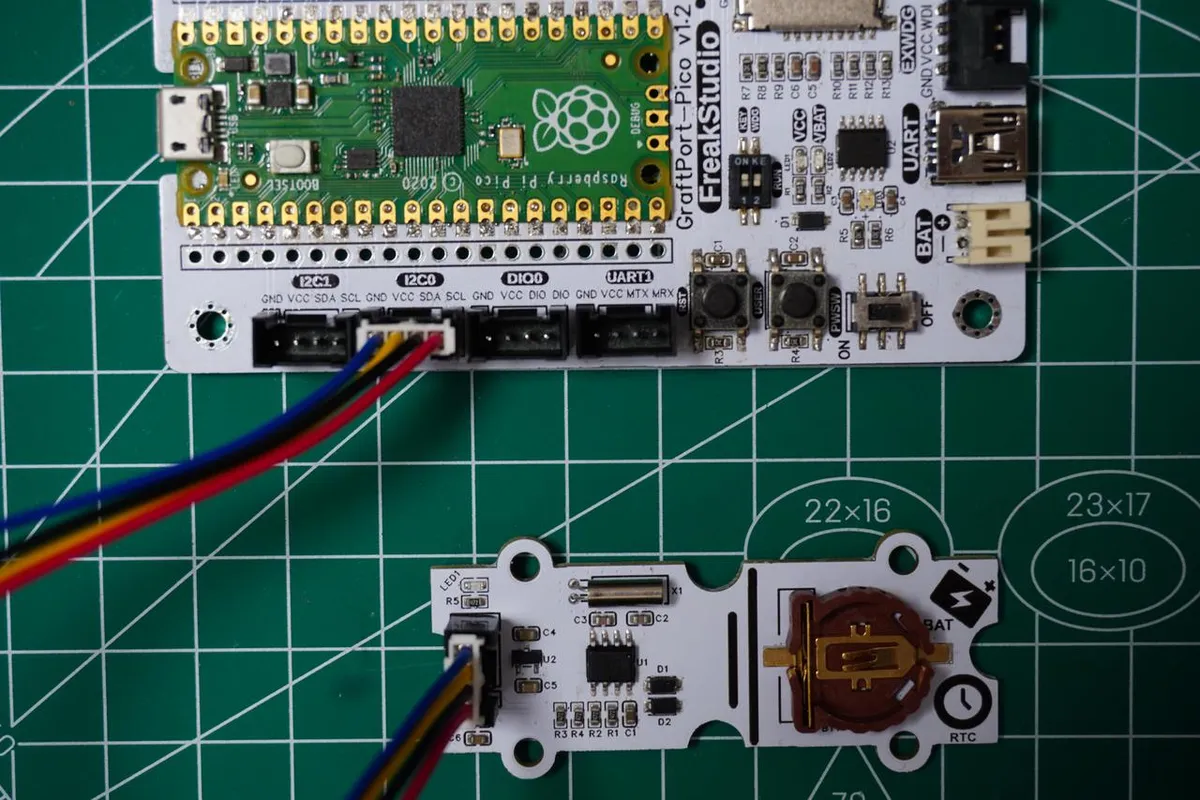
The module connections are shown in the following table:
Development Board Pins | Module Pins | Description |
Pin 4 |
|
|
Pin 5 |
|
|
Here, we need to search for the relevant driver packages on uPyPI: https://upypi.net/zh/
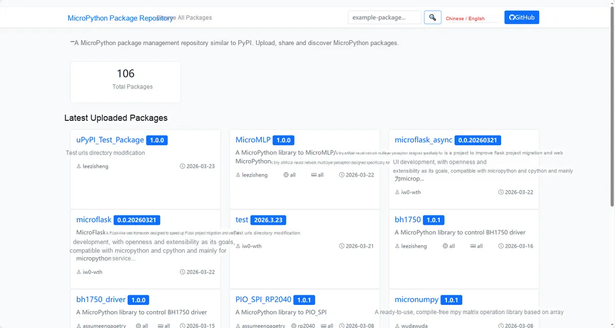
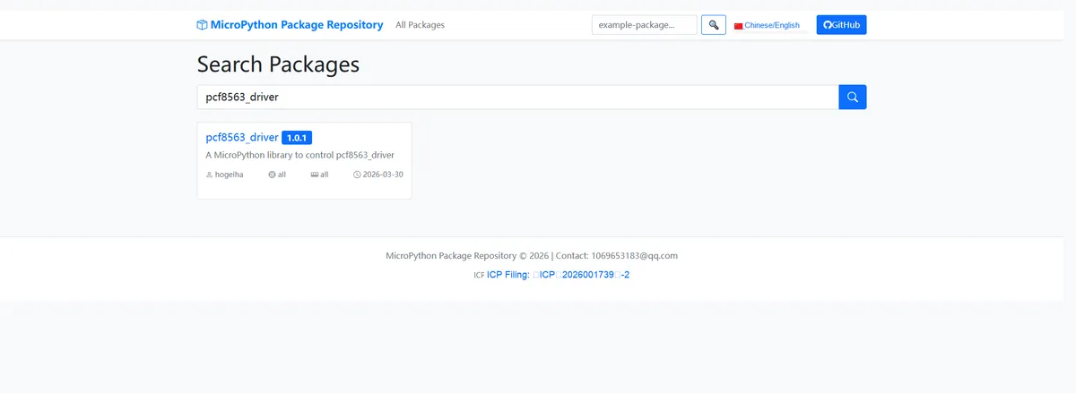
Enter pcf8563_driver to search, and the following will be displayed:
Click to copy the local installation command:
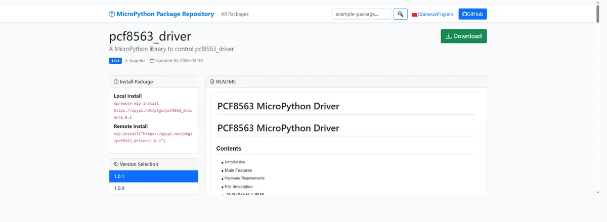
Import the module driver library code via the mip tool. Below are the usage commands for the mpremote tool:
mpremote mip install https://upypi.net/pkgs/pcf8563_driver/1.0.0Import the RTC real-time clock module based on PCF8563 - MicroPython driver code, then copy the following main.py code into our project:
# Python env   : MicroPython v1.23.0
# -*- coding: utf-8 -*-
# @Time    : 2026/3/16 8:00 PM
# @Author  : hogeiha
# @File    : main.py
# @Description : Complete usage example of the PCF8563 real-time clock module, covering core operations such as time read/write, clock output configuration and alarm function


# ======================================== Import Modules ========================================

from machine import SoftI2C, Pin
import time
import pcf8563  # Import the PCF8563 RTC module driver

# ======================================== Global Variables ============================================

# SCL pin number
I2C_SCL_PIN = 5
# SDA pin number
I2C_SDA_PIN = 4
# I2C communication frequency
I2C_FREQ = 400000
# PCF8563 default I2C address
TARGET_RTC_ADDR = 0x51

# ======================================== Functions ============================================

# ======================================== Custom Classes ============================================

# ======================================== Initialization configuration ===========================================
time.sleep(3)
print("FreakStudio: Initialize PCF8563 RTC module")

# Initialize SoftI2C
i2c_bus = SoftI2C(scl=Pin(I2C_SCL_PIN), sda=Pin(I2C_SDA_PIN), freq=I2C_FREQ)

# Scan for I2C devices
devices_list: list[int] = i2c_bus.scan()
print("START I2C SCANNER")

# 3. Check whether the scan result is empty
if len(devices_list) == 0:
    print("No i2c device !")
    raise SystemExit("I2C scan found no devices, program exited")
else:
    print("i2c devices found:", len(devices_list))

# 4. Iterate over the address list to match the target RTC address
rtc = None  # Initialize the rtc variable
for device in devices_list:
    if device == TARGET_RTC_ADDR:
        print("I2c hexadecimal address:", hex(device))
        try:
            rtc = pcf8563.PCF8563(i2c_bus)
            print("Target RTC (PCF8563) initialization successful")
            break
        except Exception as e:
            print(f"RTC Initialization failed: {e}")
            continue
else:
    # Raise an exception if the target address is not found after iterating
    raise Exception("No PCF8563 RTC module found at I2C address 0x51")

# ========================================  Main Program  ============================================
print("\n=== 2. Basic time operations ===")

# Sync the system time to the RTC module
print("Synchronize system time to RTC...")
rtc.write_now()
time.sleep(0.1)

# Read the full time
dt = rtc.datetime()
print(f"Complete time tuple: {dt} → Format: 20{dt[0]} year {dt[1]} month {dt[2]} day Week {dt[3]} {dt[4]}:{dt[5]}:{dt[6]}")

# Read each time field separately
print(f"Read separately - Year: {rtc.year()} | Month: {rtc.month()} | Date: {rtc.date()}")
print(f"Read separately - Hours: {rtc.hours()} | Minutes: {rtc.minutes()} | Seconds: {rtc.seconds()} | Weekday: {rtc.day()}")

# Manually modify the specified time field
print("\nModify time manually: Set hours to 10, minutes to 30...")
rtc.write_all(hours=10, minutes=30)
print(f"Time after modification: {rtc.hours()}:{rtc.minutes()} (Expected 10:30)")

# Set a complete custom time
custom_dt = (25, 12, 25, 4, 18, 0, 0)  # Thursday, December 25, 2025 18:00:00
print(f"\nSet complete time to: 20{custom_dt[0]} year {custom_dt[1]} month {custom_dt[2]} day {custom_dt[4]}:{custom_dt[5]}")
rtc.set_datetime(custom_dt)
print(f"Verify setting result: {rtc.datetime()}")

# Clock output frequency configuration
print("\n=== 3. Clock output configuration ===")
print("Configure CLKOUT to output 1Hz square wave...")
rtc.set_clk_out_frequency(pcf8563.CLOCK_CLK_OUT_FREQ_1_HZ)

# Alarm function operations
print("\n=== 4. Alarm function operations ===")
rtc.clear_alarm()
print("Clear existing alarm configuration completed")

# Set a daily alarm
print("Set daily alarm: Trigger at 10:30...")
rtc.set_daily_alarm(hours=10, minutes=30, date=None, weekday=None)

# Enable the alarm interrupt
print("Enable alarm interrupt...")
rtc.enable_alarm_interrupt()
print(f"Is alarm interrupt enabled: {rtc.check_for_alarm_interrupt()} (Expected True)")

# Simulate waiting for the alarm to trigger
print("\nWaiting for alarm trigger (Simulate 5 seconds, modify time to trigger alarm)...")
for i in range(5):
    time.sleep(1)
    if rtc.check_if_alarm_on():
        print(f"Second {i + 1}: Alarm triggered!")
        rtc.turn_alarm_off()
        break
    else:
        print(f"Second {i + 1}: Alarm not triggered")

# Disable the alarm interrupt
print("\nDisable alarm interrupt...")
rtc.disable_alarm_interrupt()
print(f"Is alarm interrupt enabled: {rtc.check_for_alarm_interrupt()} (Expected False)")

# Clear all alarm configurations
print("Clear all alarm configurations...")
rtc.clear_alarm()

# Read the real-time clock in a loop
print("\n=== 5. Read real-time time in loop (Press Ctrl+C to stop) ===")
try:
    while True:
        current_dt = rtc.datetime()
        print(
            f"\rReal-time time: 20{current_dt[0]} year {current_dt[1]} month {current_dt[2]} day Week {current_dt[3]} {current_dt[4]:02d}:{current_dt[5]:02d}:{current_dt[6]:02d}",
            end="",
        )
        time.sleep(1)
except KeyboardInterrupt:
    print("\nStop loop, example ended")
Burn the code, open the terminal, and the output is as follows:
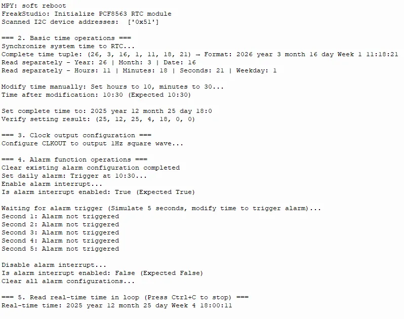
It can be seen that real-time time can be set and read in a loop, and manual time modification and alarm clock settings are supported:
- Module initialization: Complete the initialization of the PCF8563 RTC module, and the device address is scanned via I2C
0x51, confirming that the hardware connection is normal. - Basic Time Operations: Synchronize the system time to the RTC, support time reading, manual time modification, and verification of the setting result.
- Clock Output Configuration: Configure the CLKOUT pin of the RTC to output a 1Hz square wave signal.
- Alarm clock function operation: Clear the old configuration, set a daily alarm, enable/disable interrupts, and clear all alarm configurations after verifying the status.
- Real-time time reading: Enter a loop to continuously print the current RTC time, and you can press
Ctrl+ Cto terminate the program.
4. Drivers
pcf8563_driver-1.0.1.zip 13 KB
5. BOM & Recommended Alternative Parts
None.
VI. Revision History
Document Version | Date of Revision | Modifier | Modify Content |
v1.0 | 2026-03-26 | Ling Gaoxing | Initialize the document |
v1.0.1 | 2026-04-05 | Li Zisheng | The homepage photo has not been taken, the production files have not been exported yet, and all other items have been sorted out completely. |
v1.0.2 | 2026-04-14 | Li Zisheng | Modified main.py. |
v1.0.3 | 2026-04-21 | Li Zisheng | The production documents have not been exported yet, while all the others have been sorted out completely. |
v1.1 | 2026-04-23 | Xin Ruili | Create an open version of the document, based on the internal document version v1.0.3. |
VII. Relevant Materials
7.1 Chip Datasheet
PCF8563.pdf 3.0 MB
7.2 PCB Silkscreen Specific Icons