Contents
- I. Module Introduction
- II. Introduction to Main Chips
- 2.1 Chip Overview
- 2.2 Pin Definition
- 2.3 Functional Block Diagram
- 2.4 Performance Parameters
- 2.5 Reference Circuit
- 2.6 Chip Configuration
- 2.7 Communication Interfaces and Related Protocols
- 2.8 PCB Routing Notes
- III. Circuit Engineering
- 3.1 Circuit Source Engineering
- 3.2 Module Usage Instructions
- 3.3 Application Experiment
- IV. Drivers
- 5. BOM & Recommended Alternative Parts
- 6. Revision History
- VII. Relevant Materials
- 7.1 Chip Datasheet
- 7.2 Unique Icons for PCB Silk Screen
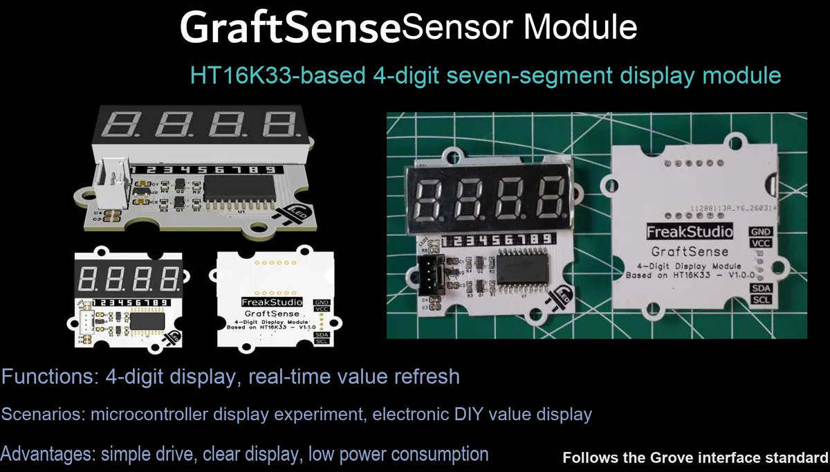
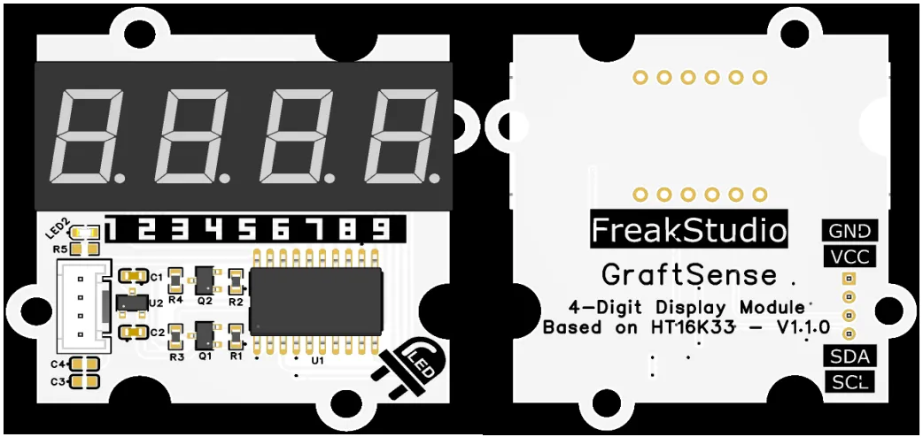
I. Module Introduction
4-digit digital tube module based on HT16K33, which adopts the HT16K33 LED driver chip solution, supports the standard I²C communication interface, has a built-in 16-level PWM dimming circuit for flexible display brightness adjustment, can provide a maximum drive current of 25mA per output, is adapted to 4.5V~5.5V power supply and equipped with power filtering and indicator light circuits, can stably drive a 4-digit digital tube to display numbers and some characters, and is suitable for application scenarios requiring intuitive digital display such as numerical display of embedded systems, digital instruments, and counters.
II. Introduction to Main Chips
HT16K33 is an I²C interface compatible LED driver chip with a built-in 16-level PWM dimming and oscillation circuit, which can directly drive common-anode / common-cathode digital tubes or dot matrix screens. It operates at a supply voltage of 4.5V~5.5V, with a maximum single-channel drive current of 40mA, and is widely used in digital display and LED matrix scenarios.
2.1 Chip Overview
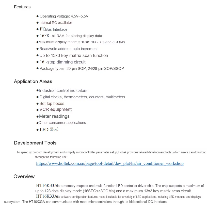
HT16K33A is a memory-mapped I²C interface compatible LED driver chip, integrating an on-chip RC oscillator and 16-level PWM dimming circuit. It supports a maximum 16×8 dot matrix display and 13×3 key matrix scanning, operates at a supply voltage of 4.5V~5.5V, and is suitable for LED display scenarios such as industrial indicators and digital instruments.
2.2 Pin Definition
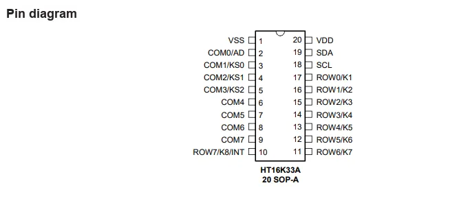
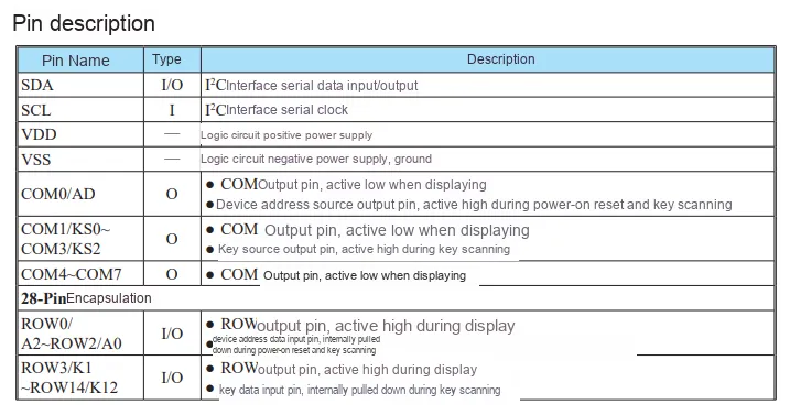
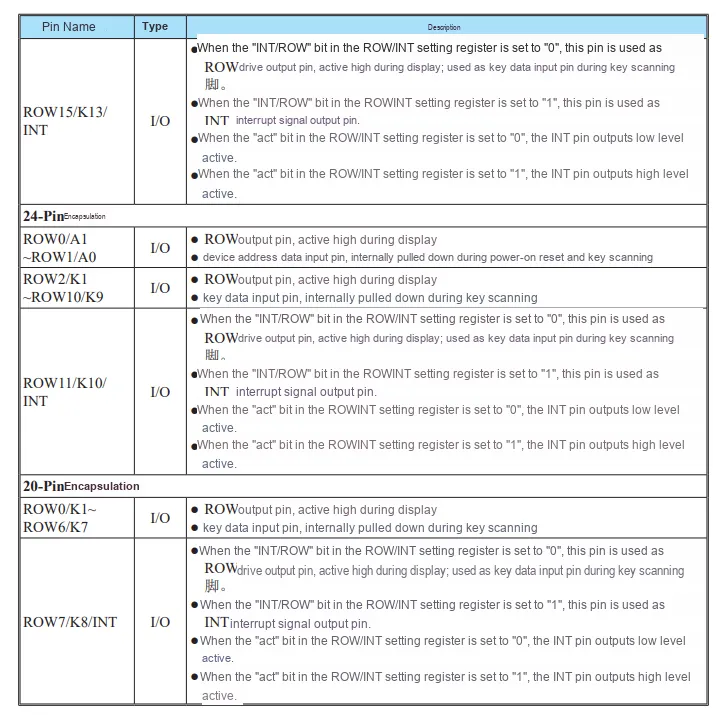
2.3 Functional Block Diagram
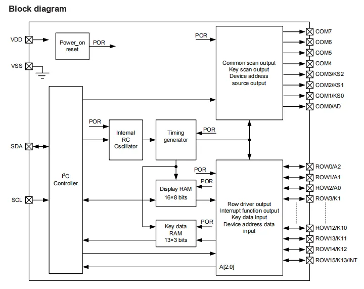
HT16K33A Core Working Principle: The chip receives I²C communication commands via the SDA / SCL pins through its controller, with the internal RC oscillator providing the clock signal, and the timing generator synchronizes all modules;After power-on reset (POR), the RAM (16×8 bits) stores the LED dot matrix data, and the key data RAM (13×3 bits) stores the key scanning results. The row driver and common terminal scanning circuit cooperatively output driving signals to realize the functions of LED dot matrix display and 13×3 key matrix scanning. It also supports device address configuration and interrupt output, completing the entire process from communication to display/key detection.
2.4 Performance Parameters
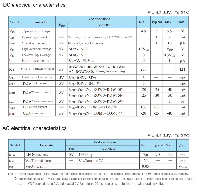
HT16K33A DC and AC electrical characteristics under the conditions of VDD = 4.5~5.5V and Ta = 25°C:
- DC Characteristics: Operating voltage 4.5~5.5V, typical operating current 1mA, standby current as low as 1μA; input high level ≥0.7
VDD, input low level ≤0.3VDD,ROWpins with a maximum sink current of 40mA,COMpins with a maximum sink current of 200mA, capable of directly driving digital tubes orLEDdot matrix. - AC characteristics:
LEDtypical frame time is 9.5ms;VDDneeds to be held at 0V for at least 20ms after shutdown to ensure reliable reset, with a voltage slew rate of 0.05V/ms.
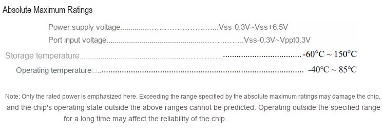
HT16K33 series chips' absolute maximum ratings define their non-negotiable safety boundaries: the power supply voltage range is VSS −0.3V to VSS + 6.5V, the port input voltage range is VSS −0.3V to VDD + 0.3V, the operating temperature range is −40°C to 85°C, and the storage temperature range is −60°C to 150°C; exceeding these ranges will cause permanent damage to the chip, and long-term operation beyond the ranges will also degrade the device' s reliability.
2.5 Reference Circuit
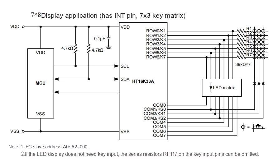
HT16K33A-20SOP typical application circuit: MCU communicates with I²C interface (SCL / SDA with 4.7kΩ pull-up resistors) to HT16K33A; the chip drives a 7×8 LED dot matrix display, and meanwhile multiplexes COM / ROW pins to implement 7×3 key matrix scanning. The I²C slave address is 0x70 (A0 ~ A2 = 000), and the series resistors can be omitted when keys are not required.
2.6 Chip Configuration
None.
2.7 Communication Interfaces and Related Protocols
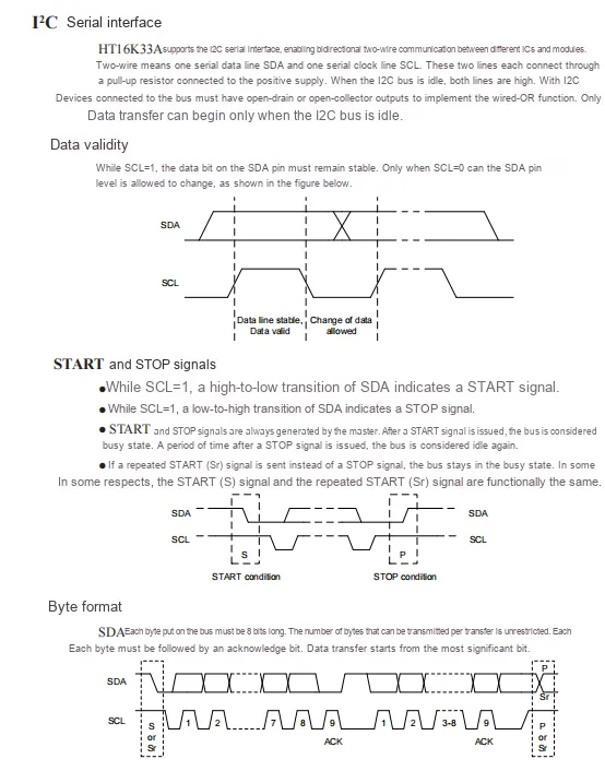
HT16K33A ’s I²C serial interface adopts SDA / SCL two-wire communication, requires external pull-up resistors, and follows the rule that SCL is at high level when SDA data is stable, and SCL is at low level when SDA is allowed to change; it uses START / STOP signals to control communication timing, and transmits data in the format of 8-bit byte + acknowledge bit.
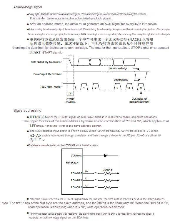
HT16K33A 's I²C acknowledgment mechanism follows each byte with an ACK acknowledgment bit (the receiver pulls SDA low); the master can send a NACK to terminate the transmission. The slave address is determined by a fixed 4-bit high-order sequence plus three address pins from A0 to A2; upon receiving a matching address, the slave outputs an ACK response and supports read/write operation selection.
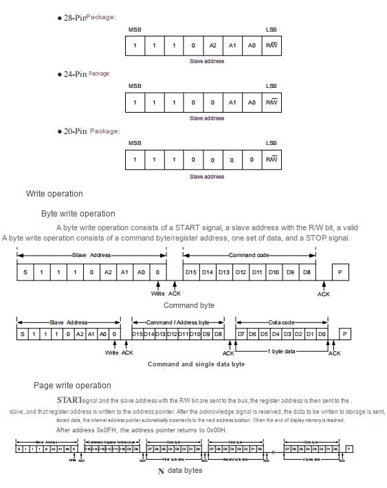
HT16K33A different packages correspond to different I²C slave address formats. Write operations are divided into byte write and page write, both starting with a START signal, followed by sequential transmission of the slave address, command/register address and data, and ending with a STOP signal; page write supports batch writing with automatic address increment.
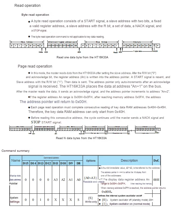
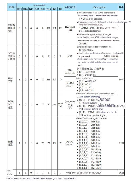
HT16K33A read operations are categorized into byte read and page read: a byte read requires sending the slave address twice to complete single-byte reading, while a page read enables continuous reading of multiple bytes (with auto-incrementing addresses). Meanwhile, this chip provides core commands such as display data address pointer and system settings for configuring display and operating modes.
2.8 PCB Routing Notes
None.
III. Circuit Engineering
3.1 Circuit Source Engineering
To obtain the circuit source project, please follow the official account [Freak Embedded].
3.2 Module Usage Instructions
The schematic diagram of this module is shown below:
SCH_4-Digit Seven-Segment Display Module Based on HT16K33-V1.0.0_2026-04-01.pdf 2.3 MB
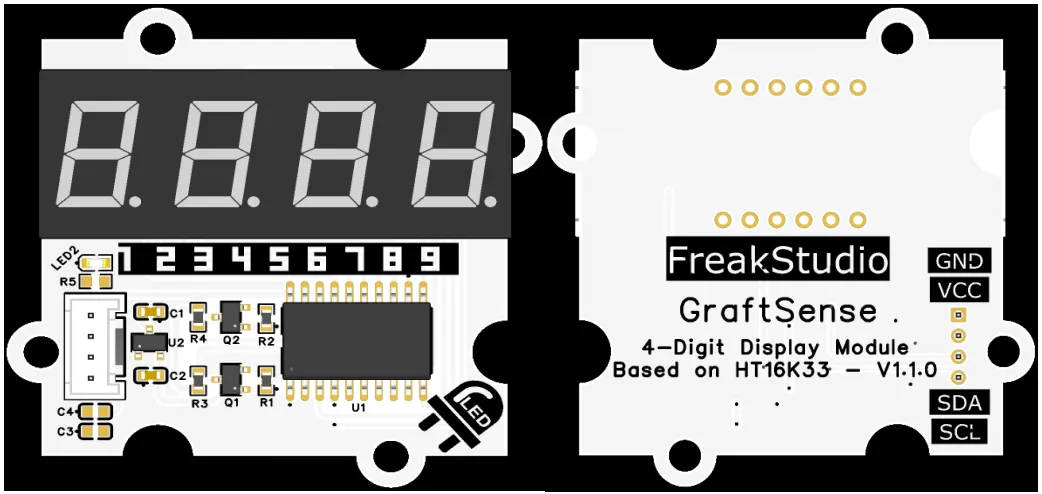
This module provides an IIC communication interface: it supports standard I²C communication rates, with a fixed slave address of 0x70. The built-in level conversion circuit is compatible with 3.3V/5V logic levels, and the display brightness can be adjusted via 16-level PWM dimming. It stably drives a 4-digit common-anode nixie tube to display numbers and symbols, and is equipped with power filtering and indicator light circuits. It is suitable for scenarios requiring intuitive digital display such as numerical display in embedded systems, digital instruments, and counters, providing simple and efficient digital interaction capabilities for the system.
3.3 Application Experiment
Here, we use the GraftPort-RP2040 development board for testing, and the 4-digit digital tube module based on HT16K33 uses the I2C interface to communicate with the main controller.
Here, we first use the HY2.0-4P cable to connect the module to the GraftPort-RP2040 development board's I2C0 interface:
The module connections are shown in the following table:
Development Board Pins | Module Pins | Description |
Pin 4 |
|
|
Pin 5 |
|
|
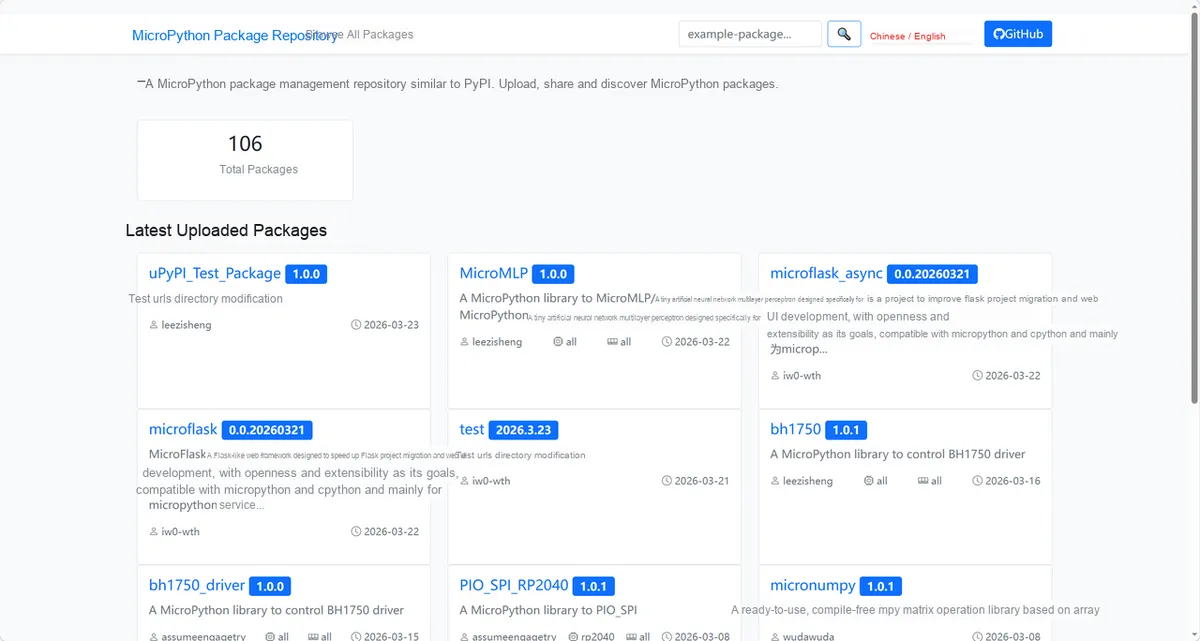
Here, we need to search for the relevant driver packages on uPyPI: https://upypi.net/zh/
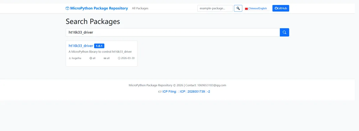
Enter ht16k33_driver to search, and the following will be displayed:
Click to copy the local installation command:
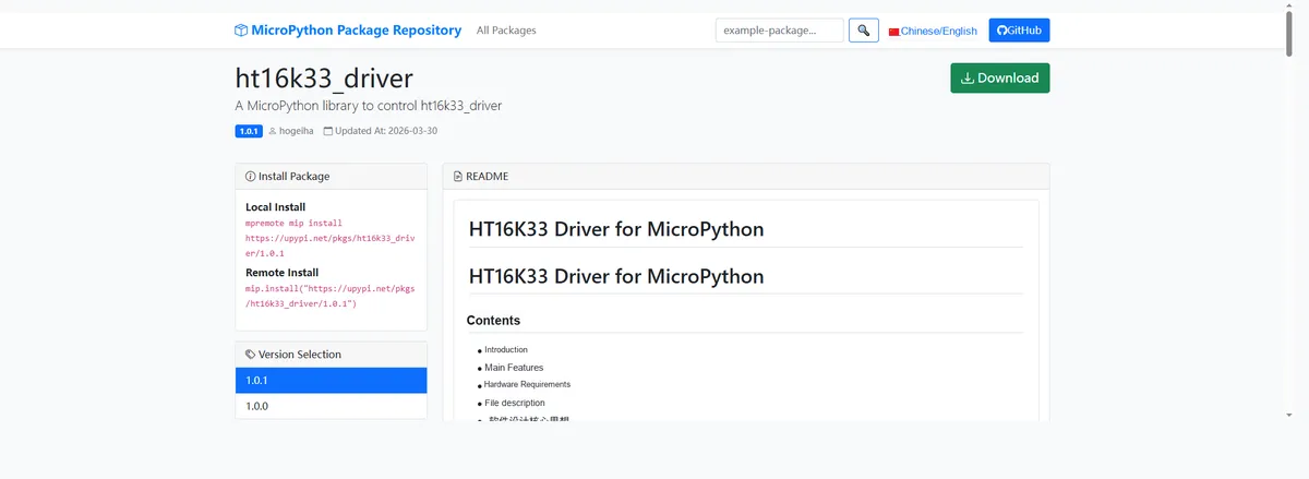
Import the module driver library code via the mip tool. Below are the usage commands for the mpremote tool:
mpremote mip install https://upypi.net/pkgs/ht16k33_driver/1.0.0Import the 4-digit digital tube module based on HT16K33 - MicroPython driver code, then copy the following main.py code into our project:
# Python env   : MicroPython v1.23.0
# -*- coding: utf-8 -*-
# @Time    : 2026/3/16 10:16 AM
# @Author  : mcauser
# @File    : main.py
# @Description : Test program for 4-digit 7-segment display based on the HT16K33 driver

# ======================================== Import Modules =========================================

# Import the I2C and Pin classes from the machine module, used for hardware I2C communication and pin control
from machine import I2C, Pin

# Import the Seg7x4 class from the ht16k33_seg module, used to control the 4-digit 7-segment display
from ht16k33_seg import Seg7x4

# Import the time module, used for delays
import time

# ======================================== Global Variables ============================================

# Define I2C-related constants (standardized configuration parameters)
I2C_SCL_PIN = 5  # SCL pin number of Pico I2C0
I2C_SDA_PIN = 4  # SDA pin number of Pico I2C0
I2C_FREQ = 400000  # I2C communication frequency (400 kHz)
TARGET_SENSOR_ADDR = 0x70  # I2C target address of the HT16K33 display (112 in decimal)

# ======================================== Functions ============================================

# ======================================== Custom Classes ============================================

# ======================================== Initialization configuration ===========================================

# Delay 3 seconds after program start to ensure hardware initialization is complete
time.sleep(3)
# Print function prompt message
print("FreakStudio: HT16K33 7-segment display test")

# Initialize the I2C bus
i2c_bus = I2C(0, scl=Pin(I2C_SCL_PIN), sda=Pin(I2C_SDA_PIN), freq=I2C_FREQ)
# Start scanning for devices on the I2C bus
devices_list: list[int] = i2c_bus.scan()
print("START I2C SCANNER")
# Check the I2C device scan result
if len(devices_list) == 0:
    print("No i2c device !")
    raise SystemExit("I2C scan found no devices, program exited")
else:
    print("i2c devices found:", len(devices_list))
# Iterate over the address list to initialize the target display
seg7 = None  # Initialize the display object variable
for device in devices_list:
    if device == TARGET_SENSOR_ADDR:
        print("I2c hexadecimal address:", hex(device))
        try:
            seg7 = Seg7x4(i2c=i2c_bus)
            print("Target sensor initialization successful")
            break
        except Exception as e:
            print(f"Sensor Initialization failed: {e}")
            continue
else:
    raise Exception("No TargetSensor found")

# ========================================  Main Program  ============================================

# Basic display test: show the number 1234
print("Display 1234")
# Clear the display buffer
seg7.fill(False)
# Set the text to display to "1234"
seg7.text("1234")
# Output the buffer contents to the display
seg7.show()
# Keep the display for 2 seconds
time.sleep(2)

# Display a number with a decimal point: show 8.888
print("Display 8.888")
# Clear the display buffer
seg7.fill(False)
# Set the text to display to "8.888"
seg7.text("8.888")
# Output the buffer contents to the display
seg7.show()
# Keep the display for 2 seconds
time.sleep(2)

# Display a hexadecimal number: show 0xFAB
print("Display hex 0xFAB")
# Clear the display buffer
seg7.fill(False)
# Set the display to the hexadecimal number 0xFAB
seg7.hex(0xFAB)
# Output the buffer contents to the display
seg7.show()
# Keep the display for 2 seconds
time.sleep(2)

# Display single characters: show 9, 8, 7, 6 in the 4 positions in turn
print("Display number 9,8,7,6")
# Clear the display buffer
seg7.fill(False)
# Show character '9' at position 0
seg7.put("9", index=0)
# Show character '8' at position 1
seg7.put("8", index=1)
# Show character '7' at position 2
seg7.put("7", index=2)
# Show character '6' at position 3
seg7.put("6", index=3)
# Output the buffer contents to the display
seg7.show()
# Keep the display for 2 seconds
time.sleep(2)

# Brightness adjustment test: cycle through brightness levels
print("Adjust brightness")
# Loop over brightness values from 0 to 15, in steps of 3
for brightness in range(0, 16, 3):
    # Set the display brightness
    seg7.brightness(brightness)
    # Hold each brightness level for 0.5 seconds
    time.sleep(0.5)

# Clear display test
print("Clear display")
# Clear the display buffer
seg7.fill(False)
# Output the cleared buffer to the display to clear the screen
seg7.show()
Burn the code, open the terminal, and the output is as follows:
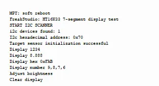
We can see that it can be displayed normally.
IV. Drivers
ht16k33_driver-1.0.2.zip 18 KB
5. BOM & Recommended Alternative Parts
None.
6. Revision History
Document Version | Date of Revision | Modifier | Modified Content |
v1.0 | 2026-03-26 | Ling Gaoxing | Initialize the document |
v1.0.1 | 2026-04-21 | Li Zisheng | The production documents have not been exported yet, while all the others have been sorted out completely. |
v1.1 | 2026-04-23 | Xin Ruili | Create an open version of the document, based on the internal document version v1.0.1. |
VII. Relevant Materials
7.1 Chip Datasheet
simHT16K33Av110.pdf 1.3 MB
7.2 Unique Icons for PCB Silk Screen