Contents
- I. Module Introduction
- II. Introduction to Major Chips
- 2.1 Chip Overview
- 2.2 Pin Definition
- 2.3 Functional Block Diagram
- 2.4 Performance Parameters
- 2.5 Reference Circuit
- 2.6 Chip Configuration
- 2.7 Communication Interfaces and Related Protocols
- 2.8 PCB Routing Precautions
- III. Circuit Engineering
- 3.1 Circuit Source Engineering
- 3.2 Module Usage Instructions
- 3.3 Application Experiment
- 4. Drivers
- 5. BOM & Recommended Alternative Parts
- VI. Revision History
- VII. Relevant Materials
- 7.1 Chip Datasheet
- 7.2 PCB Silkscreen Specific Icons
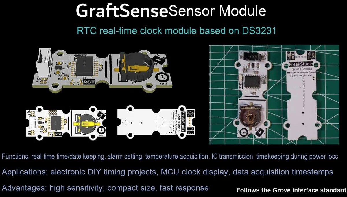
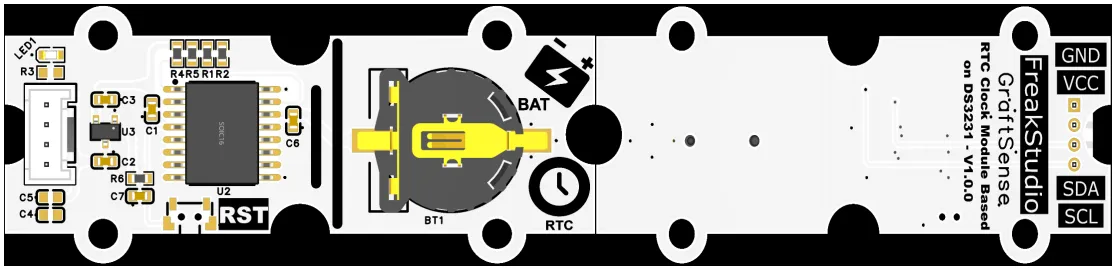
I. Module Introduction
RTC real-time clock module based on DS3231, adopts DS3231S chip solution, with built-in TCXO temperature-compensated crystal oscillator, the clock accuracy can reach ±2ppm (monthly error < 2 minutes), supports 2-channel programmable alarm + interrupt function and has a built-in temperature sensor, communicates with the main controller via the I²C interface, is equipped with a 5V to 3.3V DC-DC power supply circuit, power filtering and indicator circuit, and supports CR series button battery backup power supply. It can provide the system with high-precision and high-reliability real-time clock and temperature data, and is suitable for scenarios that require a precise time reference such as industrial timing, data loggers, and smart homes.
II. Introduction to Major Chips
DS3231 is a high-precision TCXO (temperature-compensated crystal oscillator) built-in I²C interface real-time clock (RTC) chip. It features a clock accuracy of ±2ppm, supports alarm interrupt and temperature measurement, and can be powered by a backup button cell to provide a stable and reliable time reference for the system.
2.1 Chip Overview
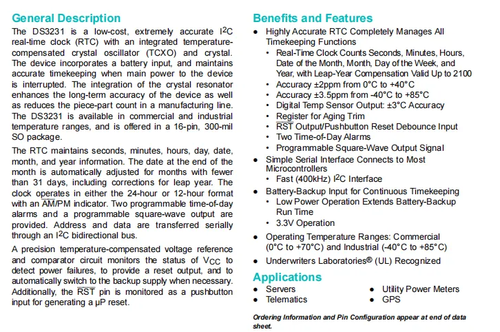
DS3231 is a high-precision TCXO -embedded I²C interface RTC chip, which delivers an accuracy of ±2ppm (0~40℃), supports alarm interrupt, programmable square wave output and temperature detection, integrates battery backup supply and power monitoring reset functions, and is suitable for scenarios requiring a precise time reference such as servers and GPS devices.
2.2 Pin Definition
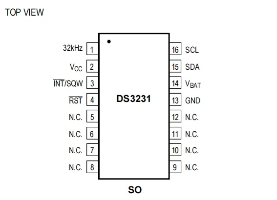
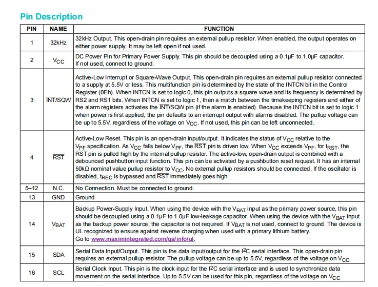
DS3231 adopts a 16-pin SO package, and its core pins include I²C communication (SCL / SDA), main power supply (VCC), backup battery (VBAT), ground (GND), multi-function interrupt/square wave output (INT / SQW), reset (RST) and 32kHz clock output, with the remaining pins being reserved (N.C.).
2.3 Functional Block Diagram
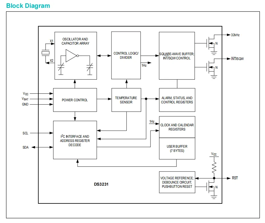
DS3231 is a high-precision real-time clock chip with an TCXO (temperature-compensated crystal oscillator) integrated and an I²C interface. It dynamically compensates the crystal oscillator frequency via an internal temperature sensor to achieve a timekeeping accuracy of ±2ppm, automatically maintains the clock and calendar with leap year correction support, features dual alarms, programmable square wave output and power supply monitoring reset function, and can maintain continuous timekeeping powered by a backup button battery. It is widely used in industrial, consumer electronics and Internet of Things scenarios that require a precise time reference.
2.4 Performance Parameters
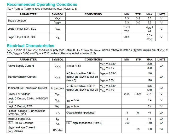
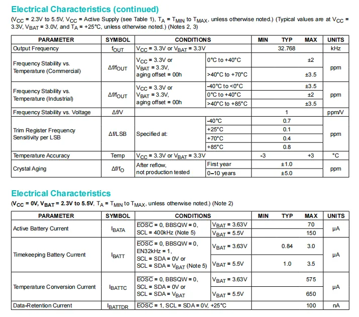
DS3231 is powered by a 2.3V~5.5V main supply and a 2.3V~5.5V backup battery. When running on the main supply, its typical standby current is only 110μA, while the current draw for timekeeping under battery backup is as low as 0.84μA; the built-in TCXO achieves a frequency stability of ±2ppm within the 0~40℃ range, with a temperature detection accuracy of ±3℃. The I²C interface is compatible with a wide level range, featuring low power consumption, high precision and high reliability electrical characteristics, making it suitable for long-term timekeeping and battery-powered scenarios.
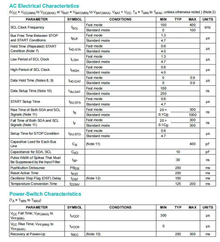
DS3231 supports two communication rates: the standard mode (100kHz) and the fast mode (400kHz) I²C communication rates, meets the timing requirements of Fast-mode (e. g., 1.3μs for SCL low level, 0.6μs for SCL high level, and 100ns for data setup time), with a maximum bus load capacitance of 400pF; it also features a 250ms key debounce and reset valid duration, a 125~200ms temperature conversion time, as well as fast switching characteristics when the main power supply drops or powers up, enabling stable low-latency communication and reliable power management.
2.5 Reference Circuit
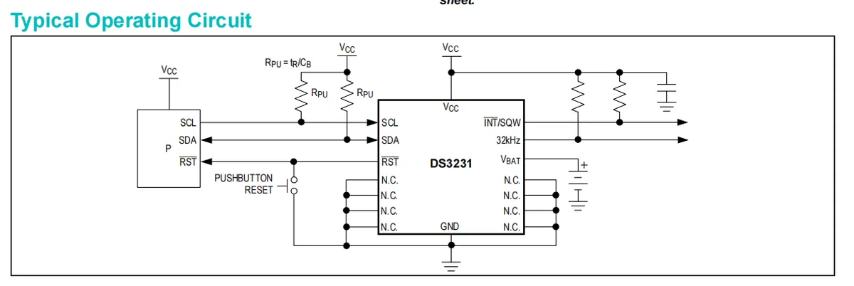
DS3231 in a typical application circuit, VCC is connected to the main power supply with a decoupling capacitor placed nearby, VBAT is connected to a coin cell battery to maintain timekeeping during power outages, SCL / SDA pins must be connected to the host controller's I²C bus after adding external pull-up resistors, INT / SQW and the 32kHz pin also require pull-up resistors to output interrupt or clock signals, RST pin can be connected to an external pushbutton for manual reset, all unused pins (N.C.) are grounded. The overall circuit is simple and reliable, capable of stably implementing high-precision real-time clock functionality.
2.6 Chip Configuration
None.
2.7 Communication Interfaces and Related Protocols
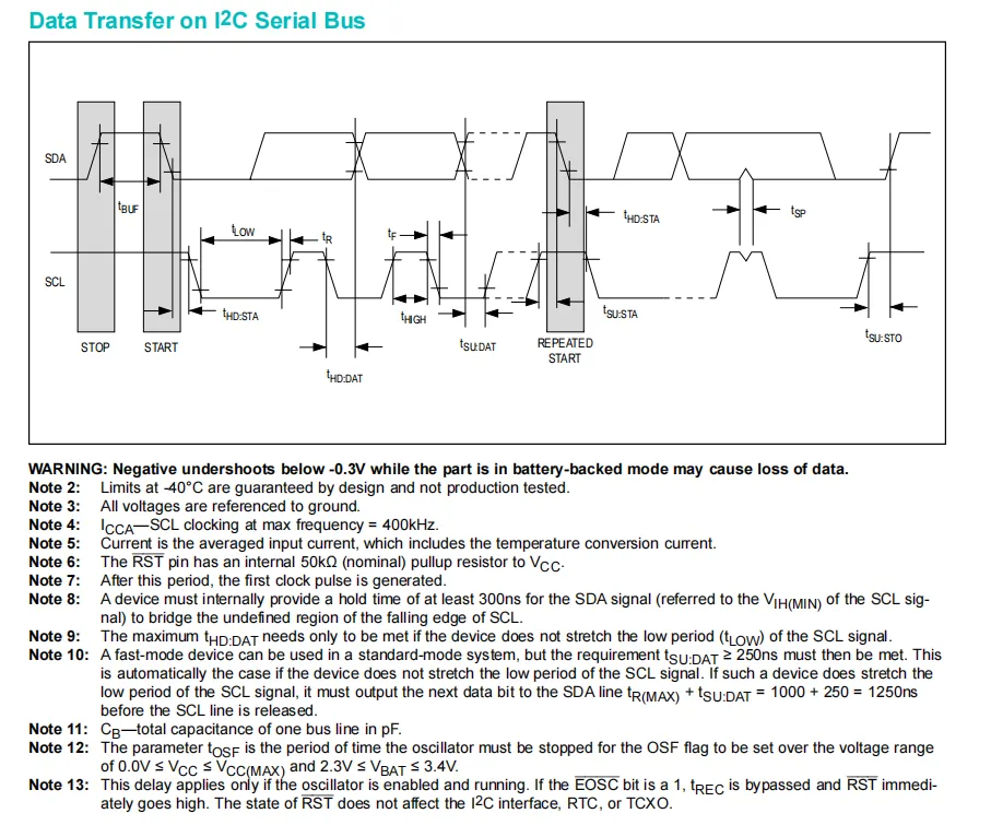
DS3231 I²C communication complies with standard and fast-mode timings, supports a maximum clock frequency of 400kHz, covers complete communication phases including START / REPEATED START / STOP, and strictly defines the high/low level durations of SCL, the data setup/hold times of SDA, as well as the bus load capacitance (max 400pF). Meanwhile, it should be noted that the negative undershoot of SDA / SCL signals in battery backup mode must not be lower than -0.3V to avoid data loss, enabling stable time data interaction with the main controller.
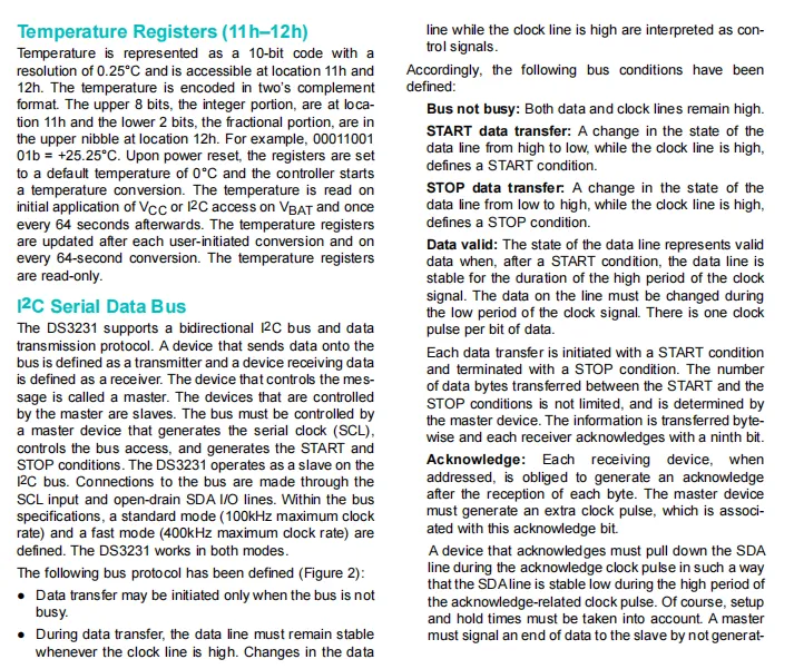
DS3231 has a temperature register in 10-bit two's complement format (resolution 0.25°C), with the address range 0x11h – 0x12h; it defaults to 0°C on power-up and automatically starts conversion, updates every 64 seconds, and the register is read-only. Its I²C interface supports both 100kHz standard mode and 400kHz fast mode, complies with complete bus protocols including START / STOP / ACK, interacts with the master as a slave, and realizes reliable transmission of time and temperature data.
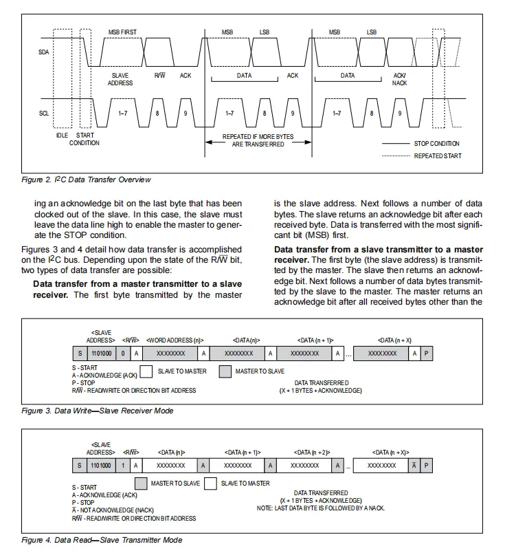
DS3231 I²C data transmission follows the master-slave mode, and communication is initiated with a 7-bit slave address (1101000) plus a read/write bit (R/W): for a write operation, the master first sends the slave address plus the write command, then transmits the register address and data bytes in sequence, and the slave returns an ACK after each byte;During a read operation, the master first sends the slave address + read command, after which the slave outputs data byte by byte (MSB first), the master returns NACK after the last byte and sends STOP to terminate the transmission. The entire process strictly complies with the START / STOP / ACK timing specifications to ensure stable and reliable data interaction.
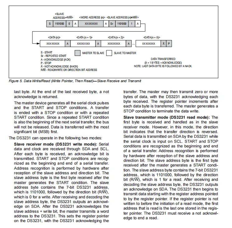
DS3231 supports two I²C modes: slave receive (write) and slave transmit (read). It also supports random address read via the composite operation of "write register pointer first, then repeat START to read": in write mode, the master sends the slave address (0x68) + write bit, then writes the register address to set the pointer;In read mode, the master sends the slave address plus the read bit, DS3231 then outputs data starting from the current pointer position (MSB first), the master returns ACK after each byte, and the last byte is terminated with NACK. The entire process strictly complies with the START / REPEATED START / STOP / ACK timing sequence, enabling efficient random read and write operations on registers.
2.8 PCB Routing Precautions
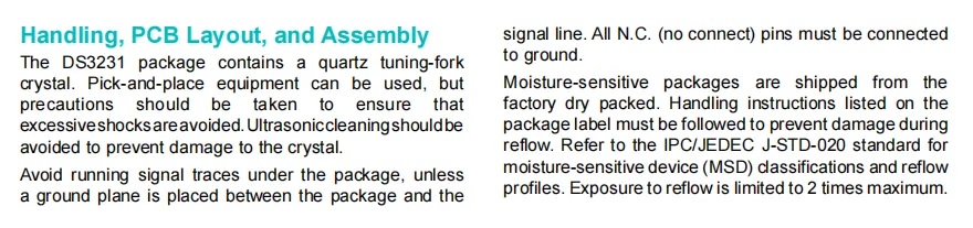
DS3231 The package has a built-in quartz tuning fork crystal oscillator. Avoid severe impact during handling and mounting, and ultrasonic cleaning is prohibited to prevent damage to the crystal oscillator;PCB layout should avoid routing signal lines under the chip (if routing is required, a ground plane shall be added for isolation), all unconnected pins (N.C.) must be grounded; This chip is a moisture-sensitive device, shipped in dry packaging. For reflow soldering, follow the label and IPC / JEDEC J-STD-020 standards, and the number of reflow cycles shall not exceed 2 at most to ensure device reliability.
III. Circuit Engineering
3.1 Circuit Source Engineering
To obtain the circuit source project, please follow the official account [Freak Embedded].
3.2 Module Usage Instructions
The schematic diagram of this module is shown below:
SCH_RTC Real-Time Clock Module Based on DS3231-V1.0.0_2026-03-26.pdf 2.3 MB
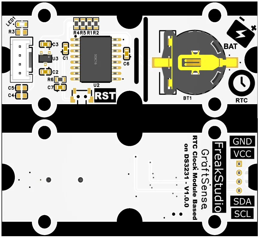
This module provides an IIC communication interface: it supports standard/fast I²C communication rates up to 400kHz, with a fixed slave address of 0x68, a built-in level adaptation circuit, and compatibility with 3.3V/5V main control levels. It can stably implement read and write operations for high-precision real-time clock and temperature data, and is suitable for scenarios requiring a precise time reference such as industrial timing, data loggers, and smart homes, providing reliable time perception and interaction capabilities for the system.
Meanwhile, this module provides CR1220 battery holder and RST reset button.
3.3 Application Experiment
Here, we use the GraftPort-RP2040 development board for testing. The DS3231-based RTC real-time clock module communicates with the main controller via the I2C interface.
Here, we first use the HY2.0-4P cable to connect the module to the GraftPort-RP2040 development board's I2C0 interface:
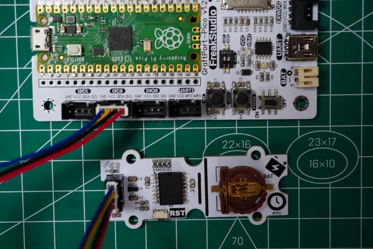
The module connections are shown in the following table:
Development Board Pins | Module Pins | Description |
Pin 4 |
|
|
Pin 5 |
|
|
Here, we need to search for the relevant driver packages on uPyPI: https://upypi.net/zh/
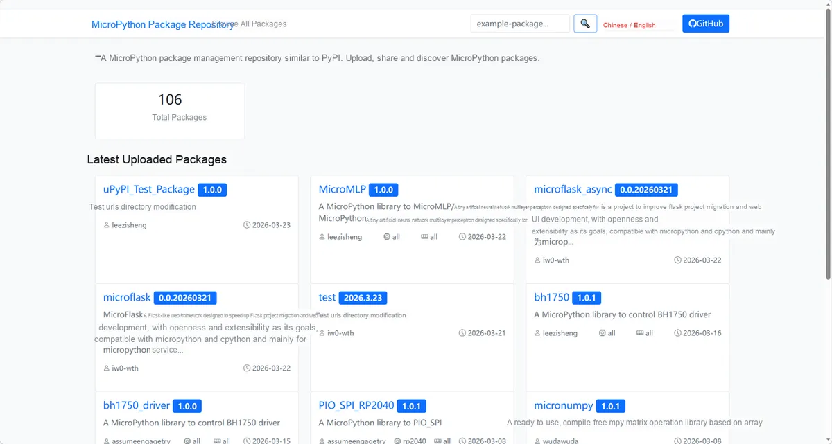
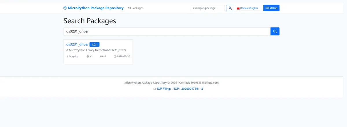
Enter ds3231_driver to search, and the following will be displayed:
Click to copy the local installation command:
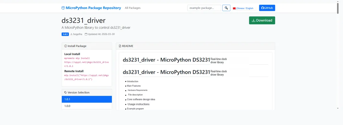
Import the module driver library code via the mip tool. Below are the usage commands for the mpremote tool:
mpremote mip install https://upypi.net/pkgs/ds3231_driver/1.0.0Import the RTC real-time clock module based on DS3231 - MicroPython driver code, then copy the following main.py code into our project:
# Python env   : MicroPython v1.23.0
# -*- coding: utf-8 -*-
# @Time    : 2026/3/13 6:00 PM
# @Author  : octaprog7
# @File    : main.py
# @Description : DS3231 real-time clock test: set and read the time, read temperature and status information, configure alarms and poll the alarm flags in a loop

# ======================================== Import Modules =========================================

# Import the I2C and Pin modules for hardware communication
from machine import I2C, Pin

# Import the DS3231 driver classes
from ds3231maxim import DS3231, I2cAdapter

# Import the time module for delays and getting local time
import time

# ======================================== Global Variables ============================================

# Define the I2C pins and frequency constants
I2C_SCL_PIN = 5
I2C_SDA_PIN = 4
I2C_FREQ = 400_000
# DS3231 default I2C address
TARGET_SENSOR_ADDR = 0x68

# ======================================== Functions ============================================

# ======================================== Custom Classes ============================================

# ======================================== Initialization configuration ===========================================

time.sleep(3)
print("FreakStudio: DS3231 RTC Clock Test and Alarm Configuration")

# Initialize the I2C bus
i2c_bus = I2C(0, scl=Pin(I2C_SCL_PIN), sda=Pin(I2C_SDA_PIN), freq=I2C_FREQ)
# Start scanning for devices on the I2C bus
devices_list: list[int] = i2c_bus.scan()
print("START I2C SCANNER")
# Check the I2C device scan result
if len(devices_list) == 0:
    print("No i2c device !")
    raise SystemExit("I2C scan found no devices, program exited")
else:
    print("i2c devices found:", len(devices_list))
    # Iterate over the address list to initialize the target sensor
    clock = None
    for device in devices_list:
        if device == TARGET_SENSOR_ADDR:
            print("I2c hexadecimal address:", hex(device))
            try:
                # Create the I2C adapter object
                adaptor = I2cAdapter(i2c_bus)
                # Create the DS3231 real-time clock object
                clock = DS3231(adapter=adaptor)
                print("Target sensor initialization successful")
                break
            except Exception as e:
                print(f"Sensor Initialization failed: {e}")
                continue
    if clock is None:
        raise Exception("No DS3231 found")

# ========================================  Main Program  ============================================

# Get the current local time
tr = time.localtime()
# Print the time to be set
print(f"set time to actual value: {tr}")
# Set the local time on the DS3231 clock
clock.set_time(tr)

# Print a prompt, calling the get_time method
print("Call get_time() method")
# Read the current DS3231 time
tr = clock.get_time()
# Print the local time that was read
print(f"Local time: {tr}")

# Read the DS3231 internal temperature sensor data
tmp = clock.get_temperature()
# Read the DS3231 status register value
stat = clock.get_status()
# Read the DS3231 control register value
ctrl = clock.get_control()
# Read the DS3231 aging offset value
ao = clock.get_aging_offset()
# Print the temperature, status, control register and aging offset values
print(f"Temperature: {tmp}\tstatus: {hex(stat)}\tcontrol: {hex(ctrl)}\taging offset: {hex(ao)}")

# Print a prompt, showing the alarm times
print("Alarm times:")
# Read and print the configuration of the first alarm (alarm 0)
print("get_alarm(0):", clock.get_alarm(0))
# Read and print the configuration of the second alarm (alarm 1)
print("get_alarm(1):", clock.get_alarm(1))

# Define the alarm time tuple (second, minute, hour, day)
at = (00, 10, 11, 12)
# Set the alarm match mode to 0 (match every second, trigger every minute)
k = 0
# Print a prompt, calling the set_alarm method
print(f"Call: set_alarm({at}, {k})")
# Configure the time and match mode of the first alarm (alarm 0)
clock.set_alarm(at, k, k)
# Read and print the first alarm information after configuration
print(f"get_alarm({k}):", clock.get_alarm(k))
# Set the alarm match mode to 1
k = 1
# Configure the time and match mode of the second alarm (alarm 1) (hour and minute match)
clock.set_alarm(at, k, k)
# Read and print the second alarm information after configuration
print(f"get_alarm({k}):", clock.get_alarm(k))

# Print a prompt, using an iterator to read the time
print("Using iterator...")
# Loop, iterating to read the DS3231 time and check the alarm flag
for ltime in clock:
    # Get the alarm trigger flag
    f = clock.get_alarm_flags()
    # Print the current time and alarm flag
    print(f"Local time: {ltime}\talarm flags: {f}")
    # Delay 1 second
    time.sleep_ms(1000)
Burn the code, open the terminal, and the output is as follows:
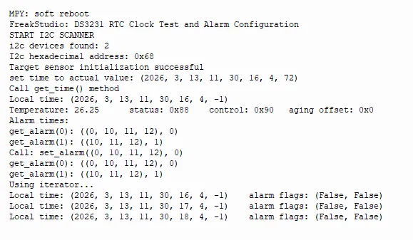
In the code above, you can see that we have successfully set the time, read the temperature, and printed the relevant data in a loop.
4. Drivers
ds3231_driver-1.0.1.zip 17 KB
5. BOM & Recommended Alternative Parts
None.
VI. Revision History
Document Version | Date of Revision | Modifier | Modify Content |
v1.0 | 2026-03-26 | Ling Gaoxing | Initialize the document |
v1.0.1 | 2026-04-05 | Li Zisheng | The homepage photo has not been taken, the production files have not been exported yet, and all other items have been sorted out completely. |
v1.0.2 | 2026-04-21 | Li Zisheng | The production documents have not been exported yet, while all the others have been sorted out completely. |
v1.1 | 2026-04-23 | Xin Ruili | Create an open version of the document, based on the internal document version v1.0.2. |
VII. Relevant Materials
7.1 Chip Datasheet
DS3231.pdf 824 KB
7.2 PCB Silkscreen Specific Icons