Contents
- I. Module Introduction
- II. Introduction to Major Chips
- 2.1 Chip Overview
- 2.2 Pin Definition
- 2.3 Functional Block Diagram
- 2.4 Performance Parameters
- 2.5 Reference Circuit
- 2.6 Chip Configuration
- 2.7 Communication Interfaces and Related Protocols
- 2.8 PCB Routing Precautions
- III. Circuit Engineering
- 3.1 Circuit Source Engineering
- 3.2 Module Usage Instructions
- 3.3 Application Experiment
- 4. Drivers
- 5. BOM & Recommended Alternative Parts
- VI. Revision History
- VII. Relevant Materials
- 7.1 Chip Datasheet
- 7.2 PCB Silkscreen Specific Icons
I. Module Introduction
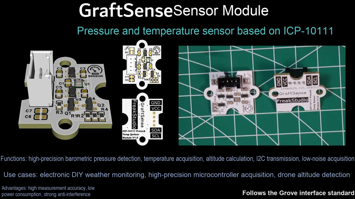
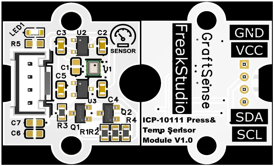
Pressure and Temperature Sensor Module Based on ICP-10111, which can measure pressure and temperature synchronously, features a pressure noise as low as 0.8 Pa and a temperature accuracy of ±0.4℃. It is built with dual power adaptation circuits (5V to 1.8V and 5V to 3.3V) and an I²C communication level conversion circuit, and is equipped with power filtering and indicator light circuits. It can realize high-precision barometric pressure and temperature Data Acquisition, and is applicable to scenarios such as wearable devices, indoor navigation, meteorological monitoring, and IoT environment perception.
II. Introduction to Major Chips
ICP-10111 is a MEMS capacitive barometric pressure/temperature sensor that features high accuracy of ±1Pa, low noise of 0.4Pa, low temperature drift of 0.5Pa/℃, and ultra-low power consumption of 1.3μA at 1Hz. It can distinguish a height difference of 8.5cm, and is suitable for scenarios such as drones, indoor navigation, and wearables.
2.1 Chip Overview
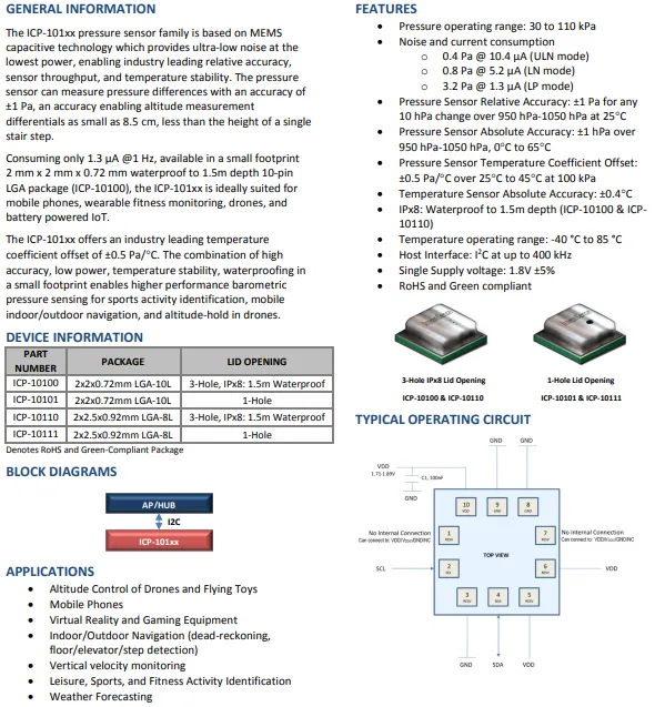
ICP-10111 is a MEMS capacitive barometric pressure/temperature sensor that adopts a 2×2.5×0.92mm LGA package, featuring high precision, low power consumption, and IPx8 waterproof performance, and is suitable for scenarios such as drones and indoor navigation.
2.2 Pin Definition
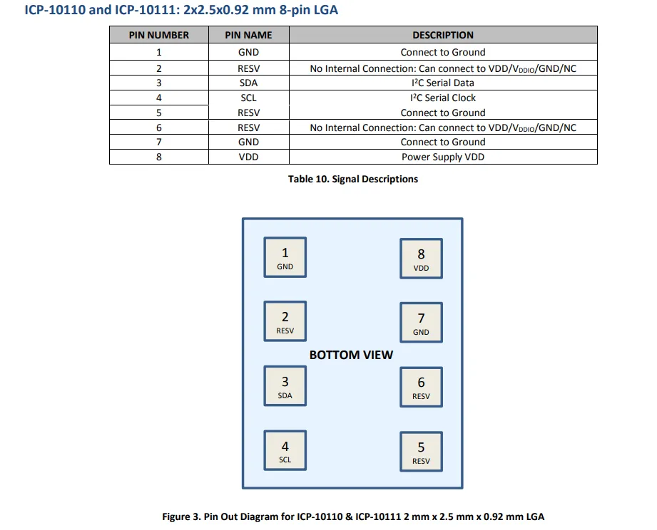
ICP-10111 (8-pin LGA package) adopts I²C communication interface, whose pins include power supply (VDD), ground (GND), I²C data (SDA) / clock (S C L) and reserved pins (RESV). With pins arranged in a symmetrical dual-in-line layout on the bottom, it supports 1.8V single-supply operation.
2.3 Functional Block Diagram
None.
2.4 Performance Parameters
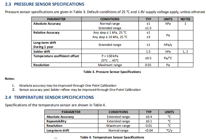
ICP-10111 The air pressure sensor features an absolute accuracy of ±1 hPa, a relative accuracy of ±1 Pa, a resolution of 0.01 Pa, and a temperature drift of ±0.5 Pa/℃; its supporting temperature sensor has an accuracy of ±0.4℃ and a resolution of 0.01℃, and the accuracy can be improved through single-point calibration.
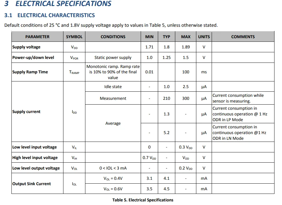
ICP-10111 operates on a single 1.71–1.89V power supply. At a 1Hz sampling rate, LP mode draws only 1.3μA average current, LN mode draws 5.2μA, and the peak current during measurement is approximately 210–300μA. The I²C interface is compatible with 1.8V logic levels, making it ideal for battery-powered IoT devices.
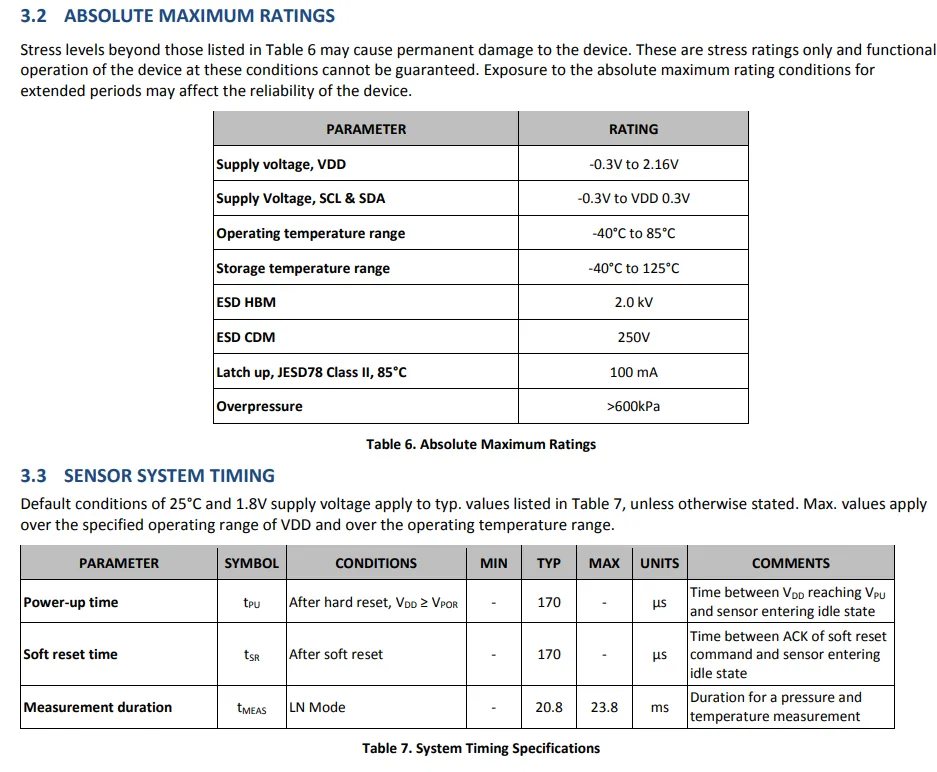
ICP-10111 has the following absolute maximum ratings: VDD -0.3V ~ 2.16V, operating temperature -40℃ ~ 85℃, ESD HBM 2.0kV, overpressure > 600kPa, the typical value of system power-on / soft reset time is 170μs, and the measurement duration in LN mode is approximately 20.8ms.
2.5 Reference Circuit
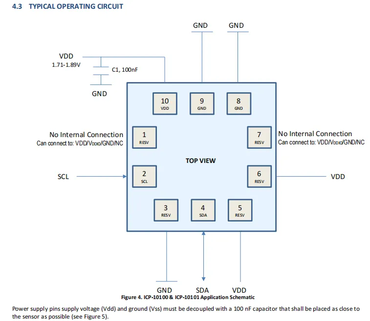
ICP-10111 typical application circuit needs to place 100nF decoupling capacitor between VDD and GND nearby , I ² C interface of SCL / SDA directly connected to the master, reserved pin ( RESV ) can be connected to VDD / GND / NC , the power supply range is 1.71-1.89V.
2.6 Chip Configuration
None.
2.7 Communication Interfaces and Related Protocols
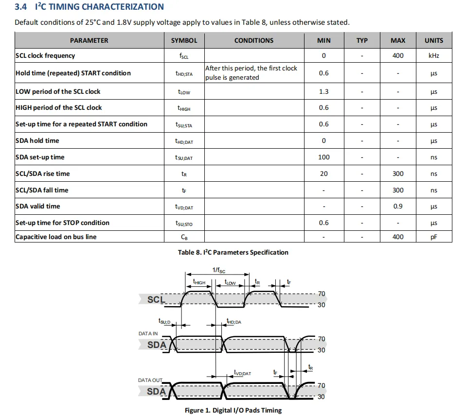
ICP-10111 supports the standard 0~400kHz I²C communication rate. For SCL, the typical low-level duration is 1.3μs and the high-level duration is 0.6μs; for SDA, the setup time is 100ns, the rise/fall time ranges from 20 to 300ns, and the maximum bus load capacitance is 400pF, which meets the timing requirements of fast I²C communication.
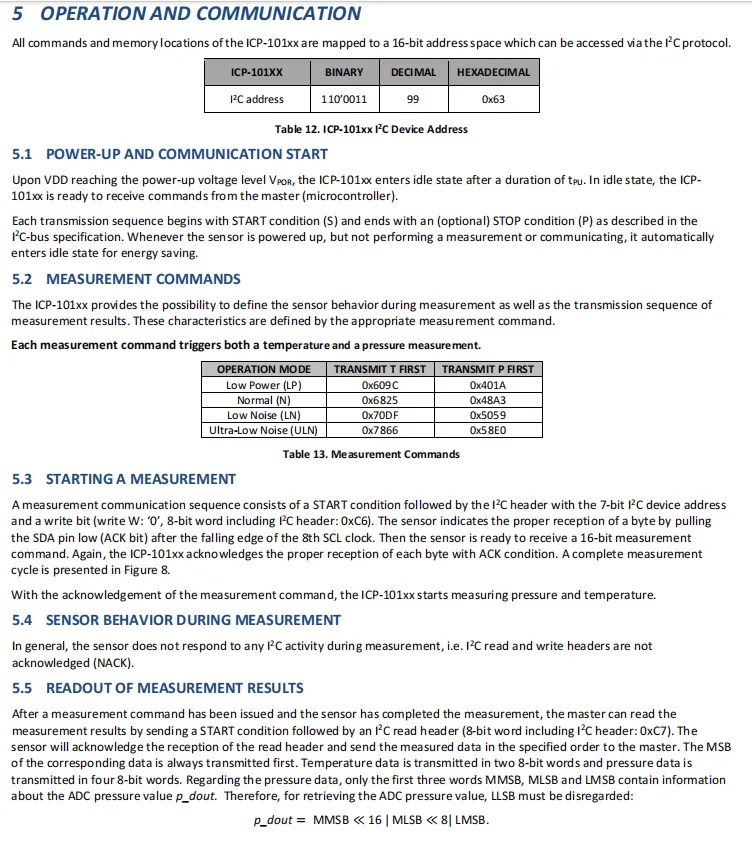
ICP-10111 communicates through the I ² C protocol (address 0x63 ) , and after power-on enters the idle state, the controller sends 0x609C / 0x6825 and other measurement instructions to start the pressure and temperature measurement, and does not respond to the I ² C activity during the measurement period. After the measurement is completed, the 24-bit result is read in the format of temperature first, pressure first, and high position first.
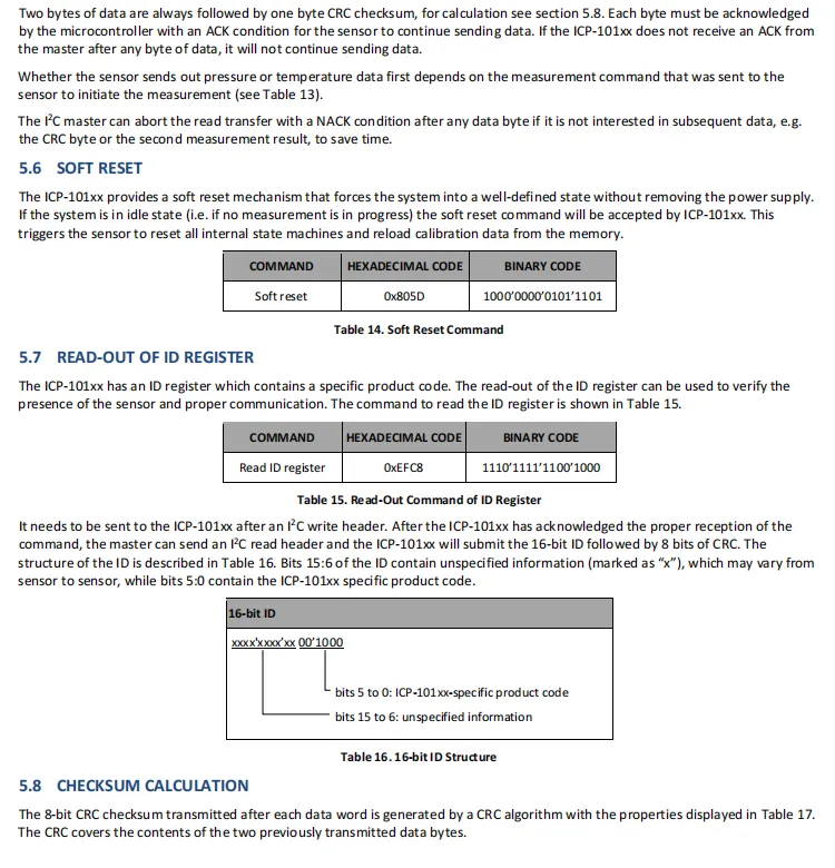
ICP-10111 supports software reset (instruction 0x805D) and ID register read (instruction 0xEFC8);data transmission comes with 8-bit CRC check. The upper 10 bits of the ID register store variable information, while the lower 6 bits represent the product model number, which can be used for communication verification and model identification.
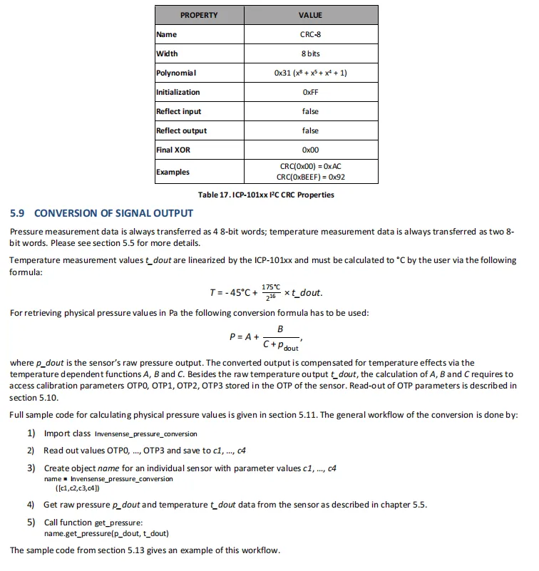
ICP-10111 adopts CRC-8 (polynomial: 0x31, initial value: 0xFF) for data check. Temperature data is linearly converted per the formula T=−45∘C+ 216175∘C× t_dout; for pressure, the calibration parameters OTP stored in the sensor A / B / C shall be combined, and the physical value is calculated via P= A + C + p_doutB.
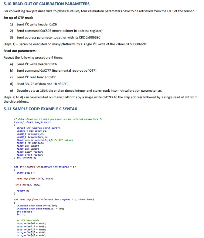
ICP-10111 requires obtaining 4 sets of 16-bit calibration parameters via I²C commands (0xC59500669C to set the OTP pointer, 0xC7F7 for incremental read), and then the official C sample code shall be used to complete the calculation and conversion of the physical pressure value.
2.8 PCB Routing Precautions
None.
III. Circuit Engineering
3.1 Circuit Source Engineering
To obtain the circuit source project, please follow the official account [Freak Embedded].
3.2 Module Usage Instructions
The schematic diagram of this module is shown below:
SCH_Pressure and Temperature Sensor Based on ICP-10111-V1.0.0_2026-03-26.pdf 2.2 MB
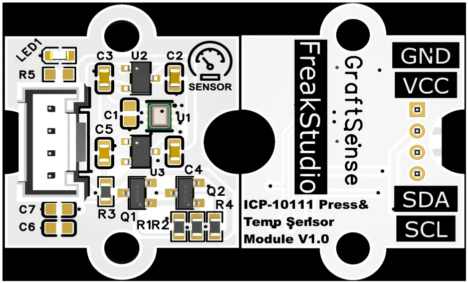
This module provides an IIC communication interface: it supports a standard I²C communication rate up to 400kHz, with a fixed device address of 0x63, a built-in level conversion circuit, and compatibility with 3.3V/5V main control levels. It can stably realize the acquisition and transmission of high-precision pressure and temperature data, and is suitable for scenarios such as wearable devices, indoor navigation, meteorological monitoring, and IoT environment sensing, providing reliable environmental parameter sensing and interaction capabilities for the system.
3.3 Application Experiment
Here, we use the GraftPort-RP2040 development board for testing, and the ICP-10111-based pressure and temperature sensor communicates with the main controller via the I2C interface.
Here, we first use the HY2.0-4P cable to connect the module to the GraftPort-RP2040 development board's I2C0 interface:
The module connections are shown in the following table:
Development Board Pins | Module Pins | Description |
Pin 4 |
|
|
Pin 5 |
|
|
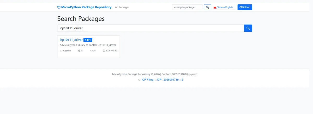
Here, we need to search for the relevant driver packages on uPyPI: https://upypi.net/zh/ :
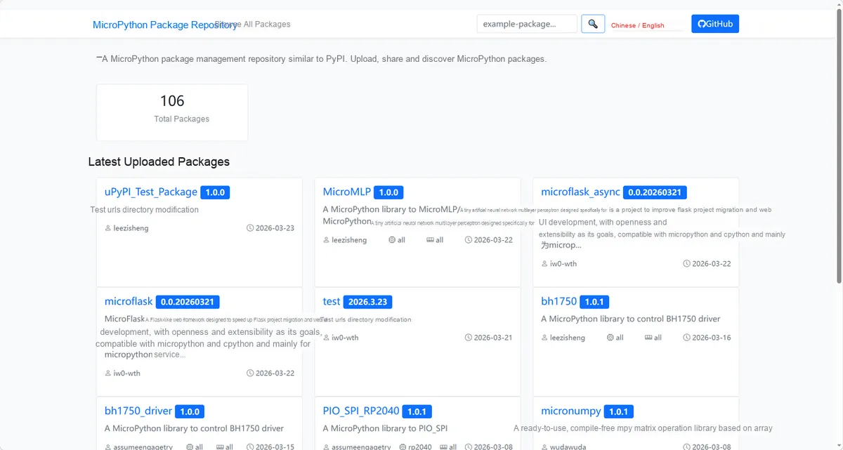
Enter icp10111_driver to search, and the following will be displayed:
Click to copy the local installation command:
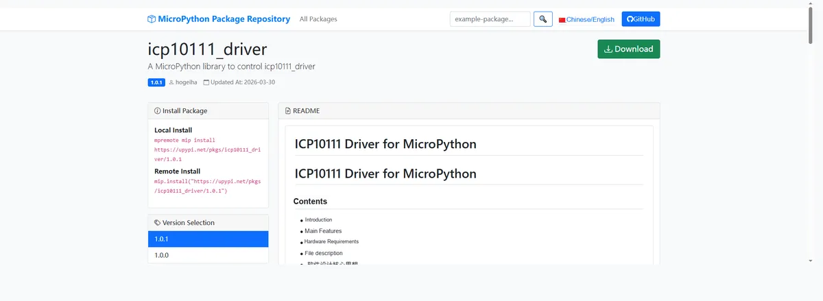
Import the module driver library code via the mip tool. Below are the usage commands for the mpremote tool:
mpremote mip install https://upypi.net/pkgs/icp10111_driver/1.0.0After importing the pressure and temperature sensor based on ICP-10111 - MicroPython driver code, copy the following main.py code into our project:
# Python env   : MicroPython v1.23.0
# -*- coding: utf-8 -*-
# @Time    : 2026/3/20 4:00 PM
# @Author  : Jose D. Montoya
# @File    : main.py
# @Description : Read air pressure and temperature data from the ICP10111 sensor and cycle through different operating modes

# ======================================== Import Modules =========================================

# Import the time module to implement delays
import time
# Import the Pin and I2C classes from the machine module, used to configure hardware pins and I2C communication
from machine import Pin, I2C
# Import the icp10111 module from the micropython_icp10111 library, used to operate the ICP10111 sensor
import icp10111

# ======================================== Global Variables ============================================

# ======================================== Functions ============================================

# ======================================== Custom Classes ============================================

# ======================================== Initialization configuration ===========================================

# Delay 3 seconds to make sure the sensor has finished initializing
time.sleep(3)
# Print the initialization message
print("FreakStudio: Read ICP10111 pressure and temperature data")

# Initialize I2C communication, using pin 4 of the RP2040 as SDA and pin 5 as SCL
i2c = I2C(0, sda=Pin(4), scl=Pin(5))  # Correct I2C pins for RP2040
# Initialize the ICP10111 sensor object, passing in the I2C instance
icp = icp10111.ICP10111(i2c)

# Set the sensor operating mode to normal mode
icp.operation_mode = icp10111.NORMAL

# ========================================  Main Program  ============================================

# Loop forever, reading data and switching modes
while True:
    # Iterate over all supported operating modes
    for operation_mode in icp10111.operation_mode_values:
        # Print the current sensor operating mode setting
        print("Current Operation mode setting: ", icp.operation_mode)
        # Read data 10 times in each mode
        for _ in range(10):
            # Get the air pressure and temperature data measured by the sensor
            press, temp = icp.measurements
            # Print the air pressure data, keeping two decimal places
            print(f"Pressure {press:.2f}KPa")
            # Print the temperature data, keeping two decimal places
            print(f"Temperature {temp:.2f}°C")
            # Print a blank line to separate each set of measurements
            print()
            # Delay 0.5 seconds before the next measurement
            time.sleep(0.5)
        # Switch the sensor to the next operating mode
        icp.operation_mode = operation_mode
Burn the code, open the terminal, and the output is as follows:
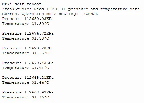
We can see that it is currently possible to switch the operation mode and print the pressure and temperature data.
4. Drivers
icp10111_driver-1.0.1.zip 11 KB
5. BOM & Recommended Alternative Parts
None.
VI. Revision History
Document Version | Date of Revision | Modifier | Modify Content |
v1.0 | 2026-03-26 | Ling Gaoxing | Initialize the document |
v1.0.1 | 2026-04-05 | Li Zisheng | The homepage photo has not been taken, the production files have not been exported yet, and all other items have been sorted out completely. |
v1.0.2 | 2026-04-21 | Li Zisheng | The production documents have not been exported yet, while all the others have been sorted out completely. |
v1.1 | 2026-04-23 | Xin Ruili | Create an open version of the document, based on the internal document version v1.0.2. |
VII. Relevant Materials
7.1 Chip Datasheet
ICP-10111.pdf 1.2 MB
7.2 PCB Silkscreen Specific Icons