Contents
- I. Module Introduction
- II. Introduction to Major Chips
- 2.1 Chip Overview
- 2.2 Pin Definition
- 2.3 Functional Block Diagram
- 2.4 Performance Parameters
- 2.5 Reference Circuit
- 2.6 Chip Configuration
- 2.7 Communication Interfaces and Related Protocols
- 2.8 PCB Routing Precautions
- III. Circuit Engineering
- 3.1 Circuit Source Engineering
- 3.2 Module Usage Instructions
- 3.3 Application Experiment
- 4. Drivers
- 5. BOM & Recommended Alternative Parts
- VI. Revision History
- VII. Relevant Materials
- 7.1 Chip Datasheet
- 7.2 PCB Silkscreen Specific Icons
I. Module Introduction
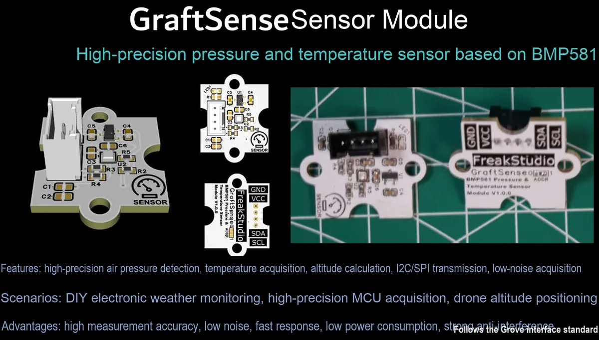
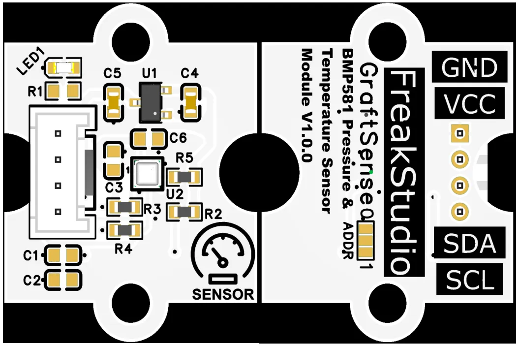
High-Precision Pressure and Temperature Sensor Module Based on BMP581 is a power supply and communication adapter board designed for the BMP581 sensor. Adopting high-precision air pressure sensing technology, it can simultaneously measure pressure within 30~125kPa and ambient temperature. Featuring low power consumption and high stability, it is suitable for scenarios such as meteorological monitoring, indoor navigation and altitude measurement.The module has a built-in 5V to 3.3V power supply circuit, and communicates with a 3.3V I²C interface with a 3.3V MCU, supporting flexible selection of either 0x76 or 0x77 as the I²C address, which facilitates mounting multiple modules on the same bus and provides the system with accurate and reliable data interaction capabilities for pressure and temperature.
II. Introduction to Major Chips
BMP581 is a high-precision, low-power barometric pressure and temperature sensor that can simultaneously measure pressure within the range of 30 to 125 kPa and ambient temperature. Featuring high stability, it is suitable for scenarios such as weather monitoring, indoor navigation and altitude measurement.
2.1 Chip Overview
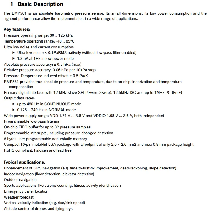
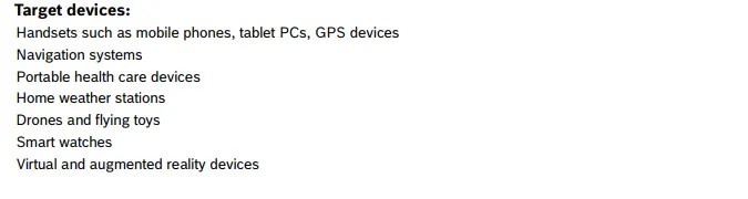
BMP581 is a high-precision, low-power absolute air pressure sensor capable of measuring pressure in the range of 30~125kPa and temperature from -40℃ to 85℃. It supports I²C / SPI interfaces, features on-chip linearization and temperature compensation, and is suitable for scenarios such as navigation, meteorological monitoring, and wearable devices.
2.2 Pin Definition
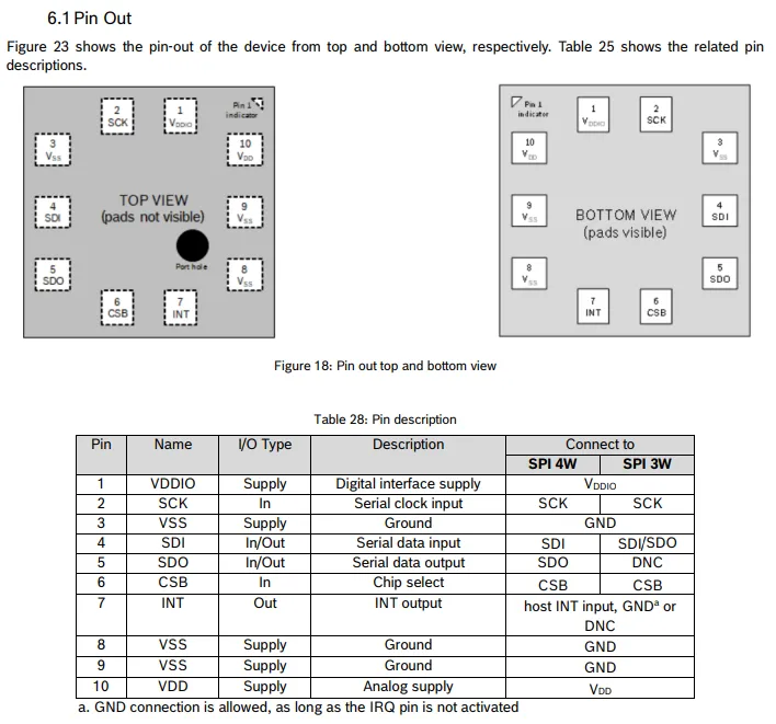
BMP581 adopts a 10-pin LGA package, and is equipped with separate digital interface power supply (VDDIO) and analog power supply (VDD). It supports SPI 4W / 3W and I²C communication, and features pins for ground, clock, data, chip select and interrupt. With clearly defined power supply and signal pins, it can flexibly adapt to the requirements of different digital interfaces.
2.3 Functional Block Diagram
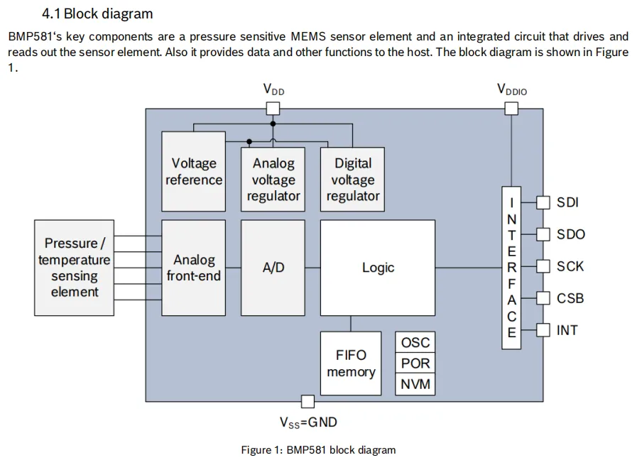
BMP581 integrates a pressure-sensitive MEMS sensing unit and signal processing circuit internally, comprising an analog front-end, ADC, logic control, FIFO buffer and power management module. It can convert analog pressure and temperature signals into digital data, and communicate with the host via the SPI / I²C interface.
2.4 Performance Parameters
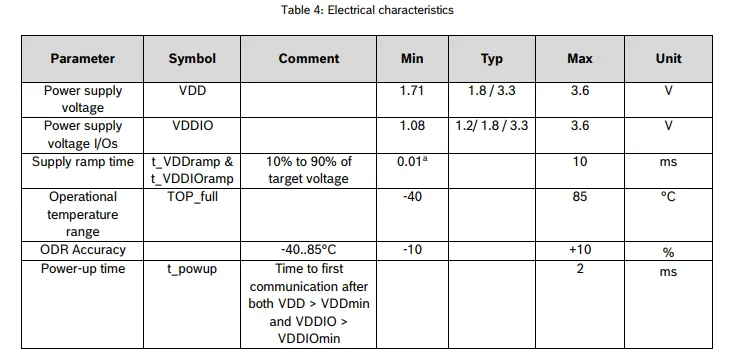
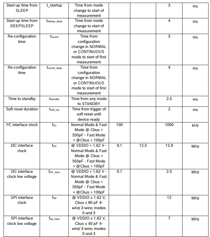

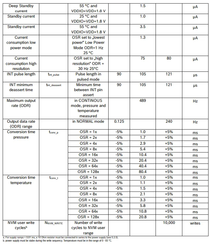
BMP581 features a wide power supply range (analog supply VDD: 1.71~3.6V, digital interface supply VDDIO: 1.08~3.6V), an operating temperature range covering -40~85℃, extremely low power consumption (deep standby current as low as 0.55μA), support for a continuous data output rate of up to 489Hz, communication interfaces compatible with clock speeds of up to 12.5MHz I³C or 12MHz SPI, as well as flexible oversampling configuration and fast startup and reset capabilities, making it a high-performance, low-power barometric pressure sensor.
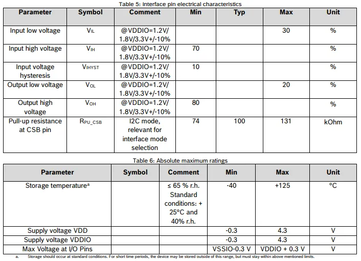
BMP581 has interface electrical characteristics referenced to VDDIO: the input low level is ≤ 30% VDDIO, the input high level is ≥ 70% VDDIO, the output low level is ≤ 20% VDDIO, the output high level is ≥ 80% VDDIO, and it features an input hysteresis of 10% VDDIO; the CSB pin has a built-in pull-up resistor of 74~131 kΩ in I²C mode.Its absolute maximum ratings are as follows: storage temperature: -40~125℃, VDD and VDDIO supply voltage tolerance: -0.3~4.3V, I/O pin voltage range is from VSS -0.3V to VDDIO + 0.3V, which can ensure the safe operation of the device in a wide range of voltage and temperature environments.
2.5 Reference Circuit
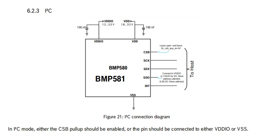
BMP581 in I²C communication mode, a 100nF decoupling capacitor shall be configured for VDD and VDDIO respectively; the CSB pin shall enable internal pull-up or be directly connected to VDDIO / VSS; the SDO pin is used to select the I²C slave address (connect to VDDIO or VSS), SCK and SDX correspond to the clock and data pins of I²C respectively, and can be directly connected to the MCU host's I²C bus for communication.
2.6 Chip Configuration
None.
2.7 Communication Interfaces and Related Protocols
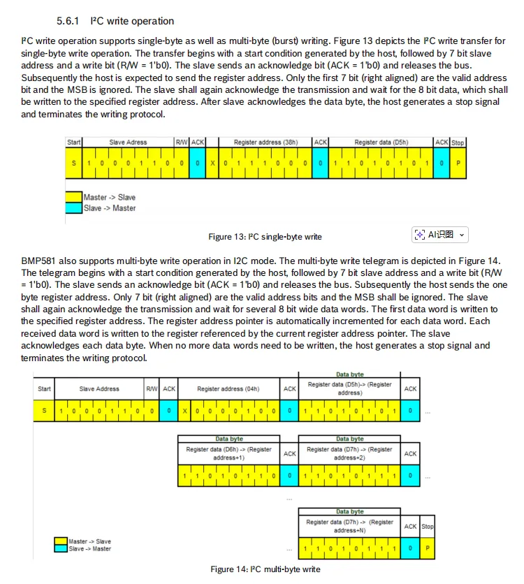
BMP581 supports single-byte and multi-byte (burst) write operations in I²C mode: after the master initiates a start condition, it sends the 7-bit slave address along with the write bit (R/W = 0); after the slave acknowledges, the master first transmits the register address and then writes the data bytes. During multi-byte writes, the register address is automatically incremented, and the slave acknowledges each byte written until the master sends a stop signal to terminate the transfer.
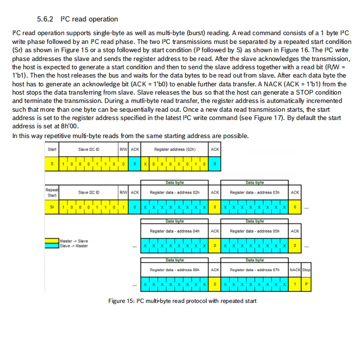
BMP581 in I²C mode supports single-byte and multi-byte (burst) read operations: the read operation consists of a write phase + read phase, and the two phases can be separated by a repeated start condition or "stop + start"; first the master sends the register address, then sends the slave address with the read bit (R/W = 1), after the slave returns data, the master can respond with an ACK to continue reading, and the register address is automatically incremented; if the master sends a NACK, the transmission ends and a stop signal is generated. The default start address is 0x8'h00, and repeated multi-byte reads from the same address are supported.
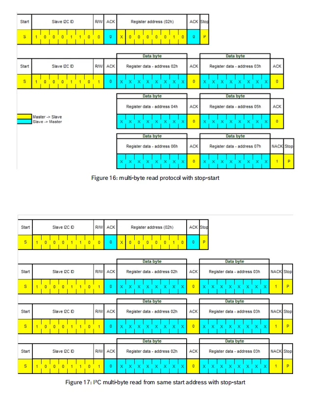
BMP581 I²C multi-byte read operation supports two transmission separation modes: Repeated Start and Stop-Start. First, specify the starting register address via a write operation, then initiate a read transfer; when the slave returns data, the master responds with ACK to continue reading with auto-incrementing address; if NACK is sent, the transfer ends. Meanwhile, the chip retains the register address specified by the most recent write operation as the starting address for new read transfers, supporting repeated multi-byte reads from the same address.
2.8 PCB Routing Precautions
None.
III. Circuit Engineering
3.1 Circuit Source Engineering
To obtain the circuit source project, please follow the official account [Freak Embedded].
3.2 Module Usage Instructions
The schematic diagram of this module is shown below:
SCH_High-Precision Pressure and Temperature Sensor Based on BMP581-V1.0.0_2026-03-25.pdf 2.3 MB
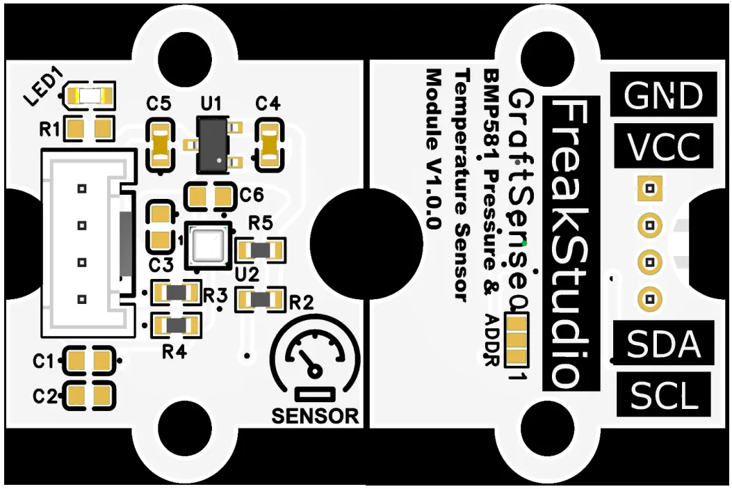
This module provides an I2C communication interface: it supports standard I2C communication rates, and either of the two ADDR soldering pads allows flexible selection between 0x76 and 0x77 as the I2C device address. Compatible with 3.3V logic level, it enables stable reading and writing of pressure and temperature data. Suitable for scenarios such as weather monitoring, indoor navigation and altitude measurement, it delivers accurate and reliable environmental data interaction capabilities for the system.
3.3 Application Experiment
Here, we use the GraftPort-RP2040 development board for testing, and the BMP581-based pressure sensor communicates with the main controller via the I2C interface.
Here, we first use the HY2.0-4P cable to connect the module to the GraftPort-RP2040 development board's I2C0 interface:
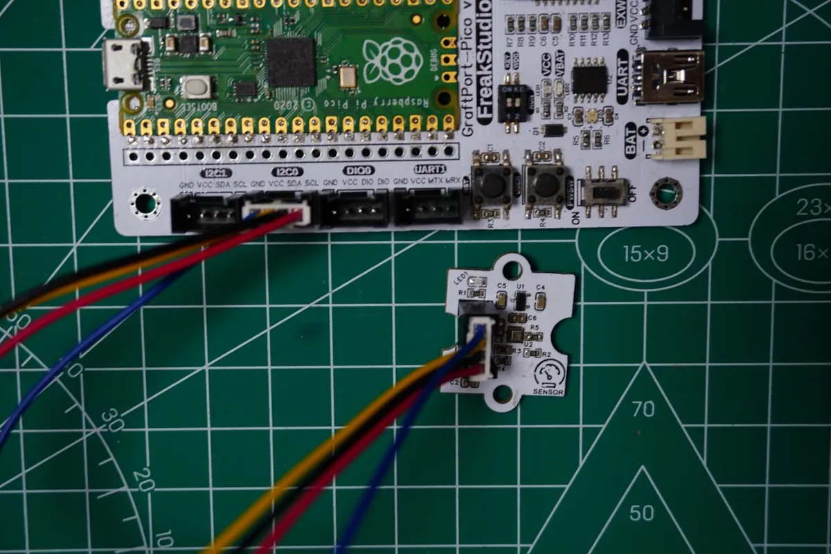
The module connections are shown in the following table:
Development Board Pins | Module Pins | Description |
Pin 4 |
|
|
Pin 5 |
|
|
Here, we need to search for the relevant driver packages on uPyPI: https://upypi.net/zh/
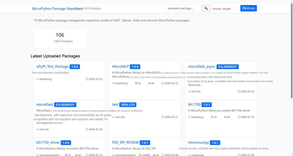
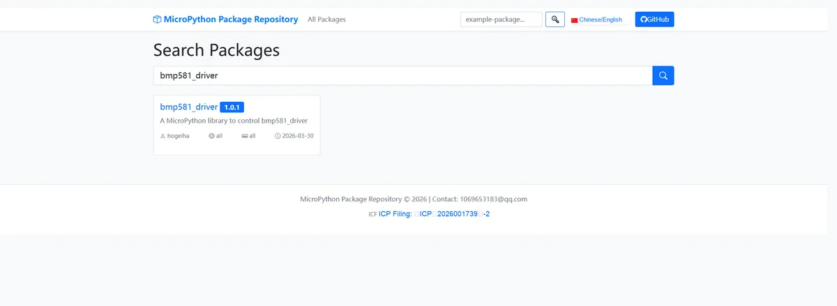
Enter bmp581_driver to search, and the following will be displayed:
Click to copy the local installation command:
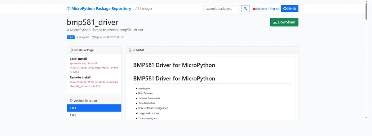
Import the module driver library code via the mip tool. Below are the usage commands for the mpremote tool:
mpremote mip install https://upypi.net/pkgs/bmp581_driver/1.0.0Import the BMP581-based pressure sensor - MicroPython driver code, then copy the following main.py code into our project:
# Python env   : MicroPython v1.23.0
# -*- coding: utf-8 -*-
# @Time    : 2026/3/23 2:00 PM
# @Author  : octaprog7
# @File    : main.py
# @Description : BMP581 temperature/pressure sensor data acquisition, supporting I2C bus scanning, sensor initialization, temperature-only measurement, simultaneous temperature and pressure measurement, and on-demand measurement mode

# ======================================== Import Modules =========================================

# Import the soft I2C and pin control modules
from machine import SoftI2C, Pin

# Import the BMP581 sensor driver module
import bmp581mod

# Import the time control module
import time

# Import the I2C adapter module
from sensor_pack.bus_service import I2cAdapter

# ======================================== Global Variables ============================================

# I2C SCL pin number of the Raspberry Pi Pico
I2C_SCL_PIN = 5
# I2C SDA pin number of the Raspberry Pi Pico
I2C_SDA_PIN = 4
# I2C bus communication frequency
I2C_FREQ = 400_000
# BMP581 sensor default I2C address (can be changed to 0x47 depending on hardware configuration)
TARGET_SENSOR_ADDR = 0x47
# Output separator, made up of 32 dashes
txt_break = 32 * "-"

# ======================================== Functions ============================================


def get_wait_time_ms(output_data_rate: int) -> int:
    """
    Calculate the data output period (in milliseconds) from the output data rate
    Args: output data rate, in Hz, range 1-400
    Raises: ValueError - raised when the output data rate is less than 1 or greater than 400
    Notes: None

    ==========================================
    Calculate data output period (ms) based on output data rate
    Args:output_data_rate: int, unit is Hz, range 1-400
    Raises:ValueError - Raised when output data rate is less than 1 or greater than 400
    Notes:None
    """
    if output_data_rate < 1 or output_data_rate > 400:
        raise ValueError("Invalid output data rate!")
    return 1 + int(1000 / output_data_rate)


# ======================================== Custom Classes ============================================

# ======================================== Initialization configuration ===========================================

# Delay the program start by 3 seconds to ensure the hardware is stable
time.sleep(3)
# Print the program start banner and function description
print("FreakStudio: BMP581 sensor data collection")

# Initialize the soft I2C bus in the specified style
i2c_bus = SoftI2C(scl=Pin(I2C_SCL_PIN), sda=Pin(I2C_SDA_PIN), freq=I2C_FREQ)

# Scan all devices on the I2C bus
devices_list: list[int] = i2c_bus.scan()
# Print the I2C scan start banner
print("START I2C SCANNER")

# Check whether the I2C scan result is empty
if len(devices_list) == 0:
    # Print the no I2C device message
    print("No i2c device !")
    # Raise an exception and exit the program
    raise SystemExit("I2C scan found no devices, program exited")
else:
    # Print the number of I2C devices found
    print("i2c devices found:", len(devices_list))

# Initialize the sensor variable to None
ps = None
# Iterate over the scanned I2C device addresses
for device in devices_list:
    # Check whether the current address is the target sensor address
    if device == TARGET_SENSOR_ADDR:
        # Print the I2C hexadecimal address of the target sensor found
        print("I2c hexadecimal address:", hex(device))
        try:
            # Create an I2C adapter instance to fit the sensor driver
            adaptor = I2cAdapter(i2c_bus)
            # Initialize the BMP581 sensor
            ps = bmp581mod.Bmp581(adaptor)
            # Print the sensor initialization success message
            print("Target sensor (BMP581) initialization successful")
            # Exit the loop after the target sensor is found
            break
        except Exception as e:
            # Print sensor initialization failure message
            print(f"Sensor Initialization failed: {e}")
            # Continue to the next address
            continue
else:
    # Raise an exception if the target sensor is not found
    raise Exception(f"No BMP581 found (target address: {hex(TARGET_SENSOR_ADDR)})")


# ========================================  Main Program  ============================================

# Perform a sensor software reset
ps.soft_reset()
# Delay 2 ms after the software reset (the reset takes at most 2 ms)
time.sleep_ms(2)

# Initialize the sensor hardware configuration
ps.init_hardware()

# Get the sensor chip ID and revision ID
res = ps.get_id()
# Print the chip ID and revision ID (hexadecimal format)
print(f"chip id: 0x{res[0]:x}\trevision id: 0x{res[1]:x}")

# Get the status information of the sensor status register (type 2)
status = ps.get_status(2)
# Parse the status register data
status_core_rdy, status_nvm_rdy, status_nvm_err, status_nvm_cmd_err, status_boot_err_corrected = status
# Print the status register parsing result
print(f"Status register: core_rdy: {status_core_rdy}, nvm_rdy: {status_nvm_rdy}, nvm_error: {status_nvm_err}, nvm_cmd_error: {status_nvm_cmd_err}")

# Get the status information of the sensor interrupt status register (type 1)
status = ps.get_status(1)
# Parse the interrupt status register data
drdy_data_reg, fifo_full, fifo_ths, oor_p, por = status
# Print the interrupt status register parsing result
print(
    f"ISR Status: data_rdy: {drdy_data_reg}, FIFO full: {fifo_full}, FIFO Threshold: {fifo_ths}, Pressure data out of range: {oor_p}, POR or software reset complete: {por}"
)

# Check whether the sensor core status is normal
status_ok = status_nvm_rdy and not status_nvm_err and por
if status_ok:
    # Print the sensor status normal message
    print("Sensor status is normal!")
else:
    # Print the sensor status abnormal message
    print("Sensor status is abnormal. Possible malfunction!")

# Print the separator
print(txt_break)
# Print the message for reading the sensor's current configuration
print("Current settings read from the sensor.")

# Get the sensor oversampling configuration
_oversampling = ps.oversampling
# Get the sensor power mode
_pwr_mode = ps.power_mode
# Get the sensor output data rate
_output_data_rate = ps.output_data_rate
# Get the sensor IIR filter configuration
iir_conf = ps.iir_config

# Print the power mode and output data rate
print(f"power mode: {_pwr_mode}; output data rate: {_output_data_rate}")
# Print the pressure and temperature oversampling configuration
print(f"pressure oversampling: {_oversampling[0]}; temperature oversampling: {_oversampling[1]}")
# Print the pressure and temperature IIR filter configuration
print(f"pressure iir: {iir_conf[0]}; temperature iir: {iir_conf[1]}")
# Print the separator
print(txt_break)

# Get the sensor effective oversampling level
osr_r = ps.effective_osr_rating
# Print the effective oversampling level and the ODR configuration verification result
print(f"Effective OSR T: {osr_r[0]}; Effective OSR P: {osr_r[1]}; ODR setting is correct: {osr_r[2]}")

# Print the separator
print(txt_break)
# Print the temperature-only measurement mode message
print("Measuring temperature only!")
# Set the sensor to temperature-only measurement mode
ps.temperature_only = True
# Set the temperature oversampling factor to 2
ps.temp_oversampling = 2
# Set the pressure oversampling factor to 2
ps.pressure_oversampling = 2
# Set the output data rate to 10 Hz
odr = 10
# Calculate the data output wait time (in milliseconds)
wt_ms = get_wait_time_ms(odr)
# Print the data output period
print(f"Data output period [ms]: {wt_ms}")
# Start sensor measurement (mode 1: continuous measurement)
tmp = ps.start_measurement(mode=1, output_data_rate=odr)
if tmp:
    # Print the data rate matching message
    print("Sensor data update rate matches temperature and pressure oversampling values!")

# Loop 100 times to read temperature data
for _ in range(100):
    # Wait for the data output period
    time.sleep_ms(wt_ms)
    # Check whether data is ready
    if ps.is_data_ready():
        # Get the temperature data
        temperature = ps.get_temperature()
        # Print the temperature data (in degrees Celsius)
        print(f"Temperature [°C]: {temperature}")
    else:
        # Print the no-data-to-read message
        print("No data to read!")

# Print the separator
print(txt_break)
# Print the simultaneous temperature and pressure measurement mode message
print("Measuring temperature and pressure!")
# Turn off temperature-only measurement mode and enable simultaneous temperature and pressure measurement
ps.temperature_only = False
# Set the output data rate to 20 Hz
odr = 20
# Calculate the data output wait time (in milliseconds)
wt_ms = get_wait_time_ms(odr)
# Start sensor measurement (mode 1: continuous measurement)
tmp = ps.start_measurement(mode=1, output_data_rate=odr)
# Loop 200 times to read temperature and pressure data
for _ in range(200):
    # Wait for the data output period
    time.sleep_ms(wt_ms)
    # Check whether data is ready
    if ps.is_data_ready():
        # Get the temperature and pressure data
        temperature, pressure = ps.get_temperature(), ps.get_pressure()
        # Print the temperature (degrees Celsius) and pressure (pascals) data
        print(f"Temperature [°C]: {temperature}; Pressure [Pa]: {pressure}")
    else:
        # Print the no-data-to-read message
        print("No data to read!")

# Print the separator
print(txt_break)
# Set the output data rate to 5 Hz in on-demand measurement mode
odr = 5
# Calculate the data output wait time (in milliseconds)
wt_ms = get_wait_time_ms(odr)
# Print the on-demand measurement mode message
print("On-demand measurement mode! Temperature and pressure!")
# Print the iterator protocol usage message
print("Applying iterator protocol.")

# Iterate over the sensor data using the iterator
for items in ps:
    if items:
        # Parse pressure and temperature data
        pressure, temperature = items
        # Print the temperature (degrees Celsius) and pressure (pascals) data
        print(f"Temperature [°C]: {temperature}; Pressure [Pa]: {pressure}")
    else:
        # Print the no-data-to-read message
        print("No data to read!")
    # Start on-demand sensor measurement (mode 2: on-demand measurement)
    tmp = ps.start_measurement(mode=2, output_data_rate=0)
    # Wait for the data output period
    time.sleep_ms(wt_ms)

# Print the separator
print(txt_break)
Burn the code, open the terminal, and the output is as follows:
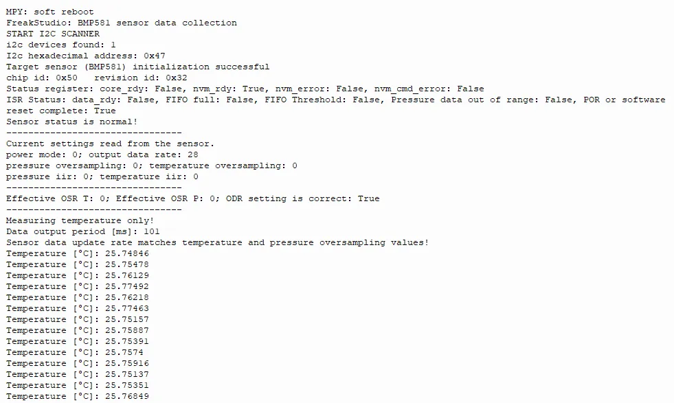
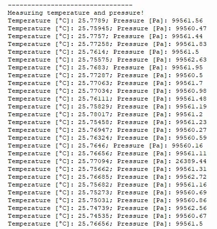
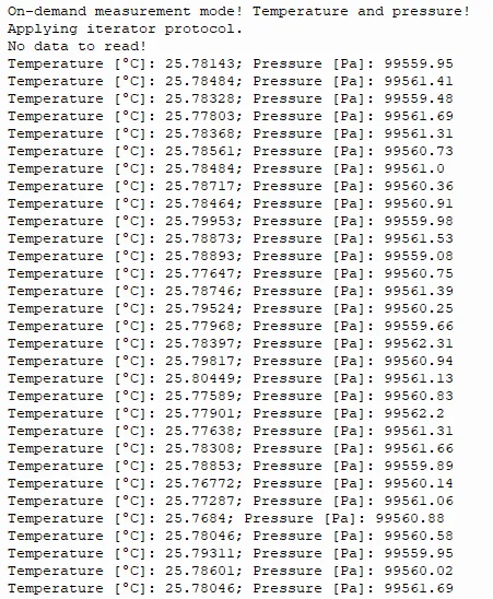
It can be seen that the operating mode has been successfully configured, and temperature and pressure data are output in a loop.
4. Drivers
bmp581_driver-1.0.1.zip 30 KB
5. BOM & Recommended Alternative Parts
None.
VI. Revision History
Document Version | Date of Revision | Modifier | Modify Content |
v1.0 | 2026-03-25 | Ling Gaoxing | Initialize the document |
v1.0.1 | 2026-04-05 | Li Zisheng | The homepage photo has not been taken, the production files have not been exported yet, and all other items have been sorted out completely. |
v1.0.2 | 2026-04-21 | Li Zisheng | The production documents have not been exported yet, while all the others have been sorted out completely. |
v1.1 | 2026-04-23 | Xin Ruili | Create an open version of the document, based on the internal document version v1.0.2. |
VII. Relevant Materials
7.1 Chip Datasheet
BMP581.pdf 2.7 MB
7.2 PCB Silkscreen Specific Icons