Contents
- I. Module Introduction
- II. Introduction to Major Chips
- 2.1 Chip Overview
- 2.2 Pin Definition
- 2.3 Functional Block Diagram
- 2.4 Performance Parameters
- 2.5 Reference Circuit
- 2.6 Chip Configuration
- 2.7 Communication Interfaces and Related Protocols
- 2.8 PCB Routing Precautions
- III. Circuit Engineering
- 3.1 Circuit Source Engineering
- 3.2 Module Usage Instructions
- 3.3 Application Experiment
- 4. Drivers
- 5. BOM & Recommended Alternative Parts
- VI. Revision History
- VII. Relevant Materials
- 7.1 Chip Datasheet
- 7.2 PCB Silkscreen Specific Icons
I. Module Introduction
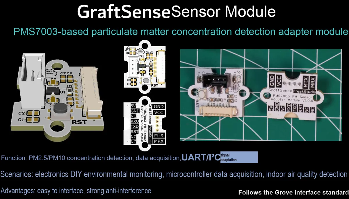
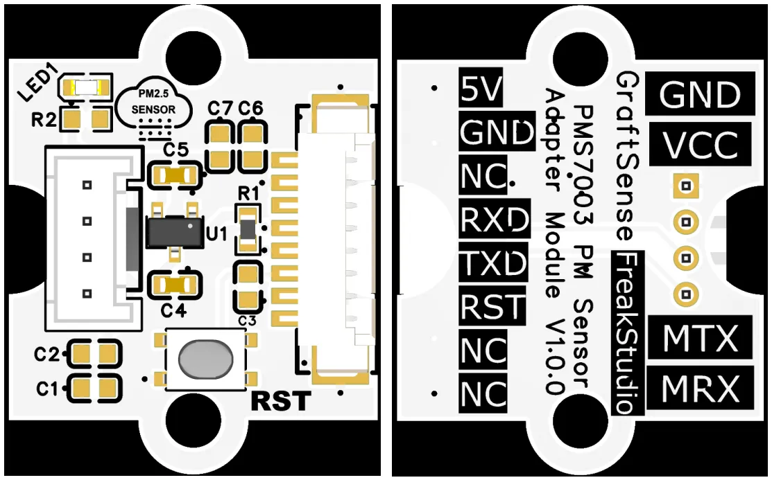
The particulate matter concentration detection adapter module based on PMS7003 is an adapter board tailored for the PMS7003 particulate matter sensor. It adopts the laser scattering principle to realize three-channel particulate matter concentration detection for PM1.0, PM2.5 and PM10, and can simultaneously output the concentration data of standard particulate matter and that under atmospheric environment.The module has built-in 5V-to-3.3V power supply circuit and reset circuit, which converts the 5V power supply and UART level of the sensor to 3.3V logic, enabling direct communication with a 3.3V MCU. It features a particulate matter concentration detection range of 0~1000μg/m³, a response time of less than 10 seconds, an integrated micro fan to ensure stable airflow, and supports two operating modes: active reporting and passive query, making it suitable for embedded scenarios such as air quality monitoring and environmental testing.
II. Introduction to Major Chips
PMS7003 is a high-precision particulate matter sensor module that adopts the laser scattering principle, professionally detects the concentrations of PM1.0, PM2.5 and PM10, and supports UART communication.
2.1 Chip Overview
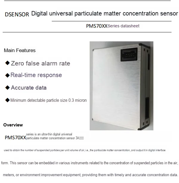
The PMS7003 series is an ultra-thin digital general-purpose particulate matter concentration sensor. Based on the laser scattering principle, it can detect the concentration of suspended particulate matter per unit volume, with a minimum resolvable particle size of 0.3μm. Featuring zero false alarm rate, real-time response and accurate data, it outputs data via a digital interface and can be embedded into relevant instruments, meters or environmental equipment for use.
2.2 Pin Definition
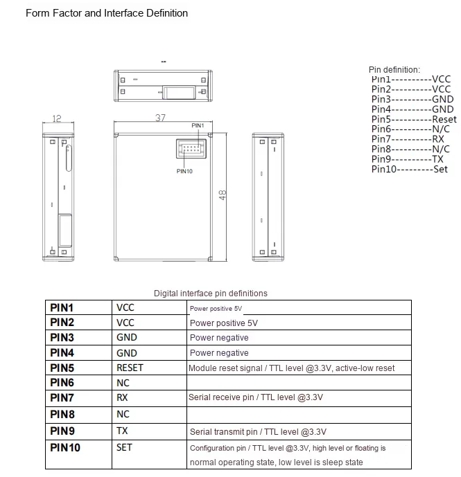
2.3 Functional Block Diagram
None.
2.4 Performance Parameters
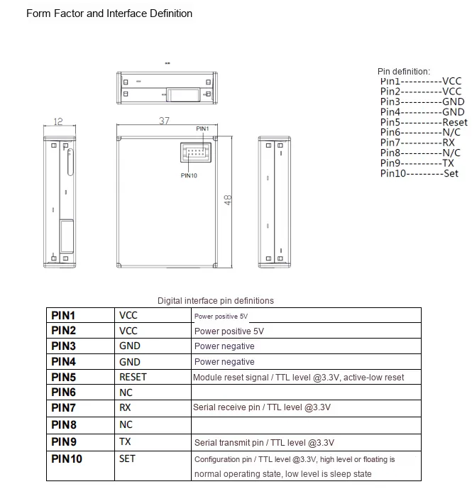
The PMS7003 series sensors adopt a 10Pin interface, which provides dual 5V power supplies and dual GND pins, supports 3.3V TTL level reset, UART communication (RX / TX) and sleep control (SET). With clearly defined pinouts, it can directly perform level-matched communication with a 3.3V MCU.
2.5 Reference Circuit
None.
2.6 Chip Configuration
None.
2.7 Communication Interfaces and Related Protocols
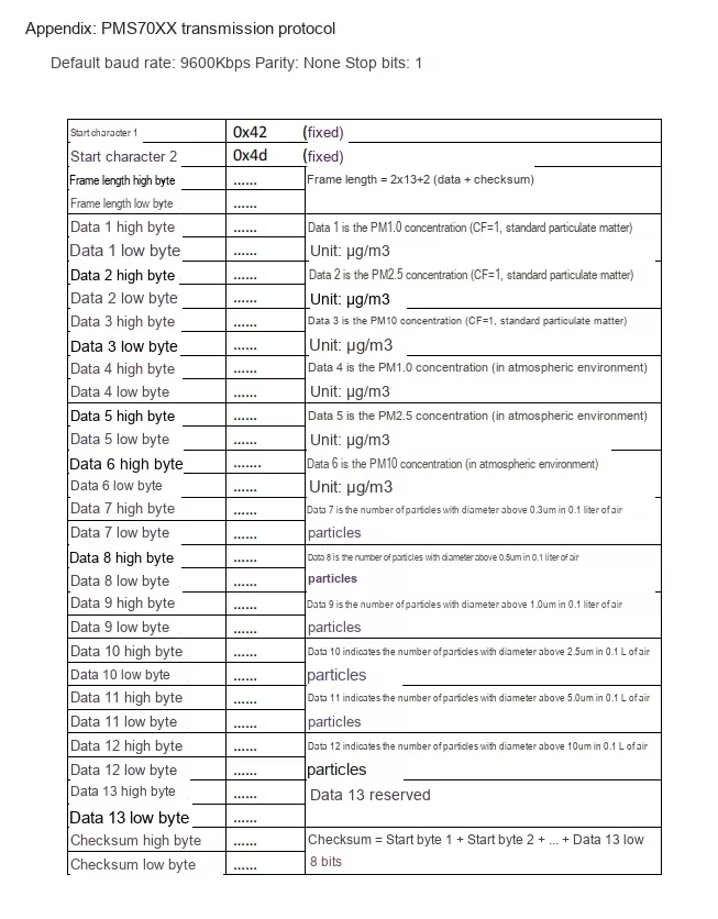
The PMS7003 series sensors use UART communication with default parameters: 9600bps baud rate, no parity, 1 stop bit. Each data frame starts with the fixed header 0x42 0x4d, and transmits a 32-byte data frame containing PM1.0 / PM2.5 / PM10 concentrations, counts of particles across multiple size bins, and a checksum, where the checksum is calculated as the sum of all preceding bytes in the frame.
2.8 PCB Routing Precautions
None.
III. Circuit Engineering
3.1 Circuit Source Engineering
To obtain the circuit source project, please follow the official account [Freak Embedded].
3.2 Module Usage Instructions
The schematic diagram of this module is shown below:
SCH_PMS7003-Based Particulate Matter Concentration Detection Adapter Module-V1.0.0_2026-03-25.pdf 2.3 MB
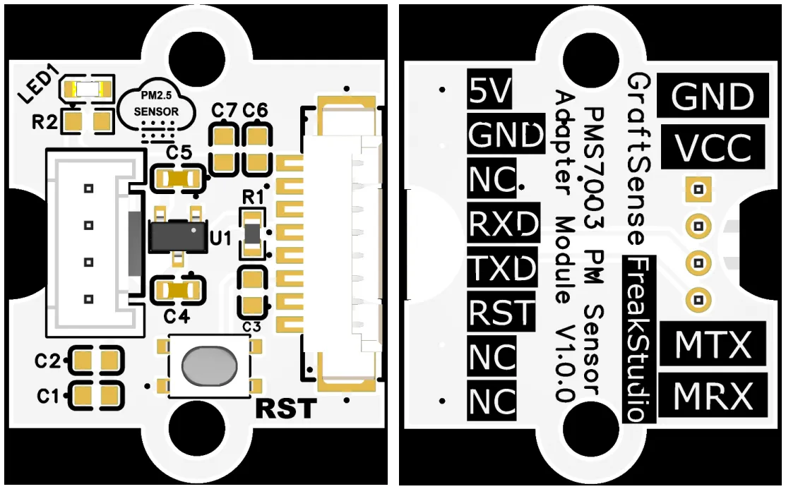
This module provides a serial port UART interface MRX and MTX: here M stands for master, meaning it is the MCU 's RX corresponding to the module' s TX; when in use, note that the communication parameters of the microcontroller's UART interface are consistent with those of the module, which can stably realize the reading and writing operations of the PMS7003T sensor's PM1.0, PM2.5, PM10 concentration data and configuration parameters. It is suitable for embedded scenarios such as air quality monitoring and environmental detection, and provides reliable particulate matter concentration data interaction capability for the system.
The module is equipped with an on-board RST reset button, which can be pressed to reset the module when necessary.
3.3 Application Experiment
Here, we use the GraftPort-RP2040 development board for testing, and the PM concentration detection adapter module based on the PMS7003 uses the UART interface to communicate with the main controller.
Here, we first use the HY2.0-4P connection cable to connect the module to the GraftPort-RP2040 development board's UART0 interface:
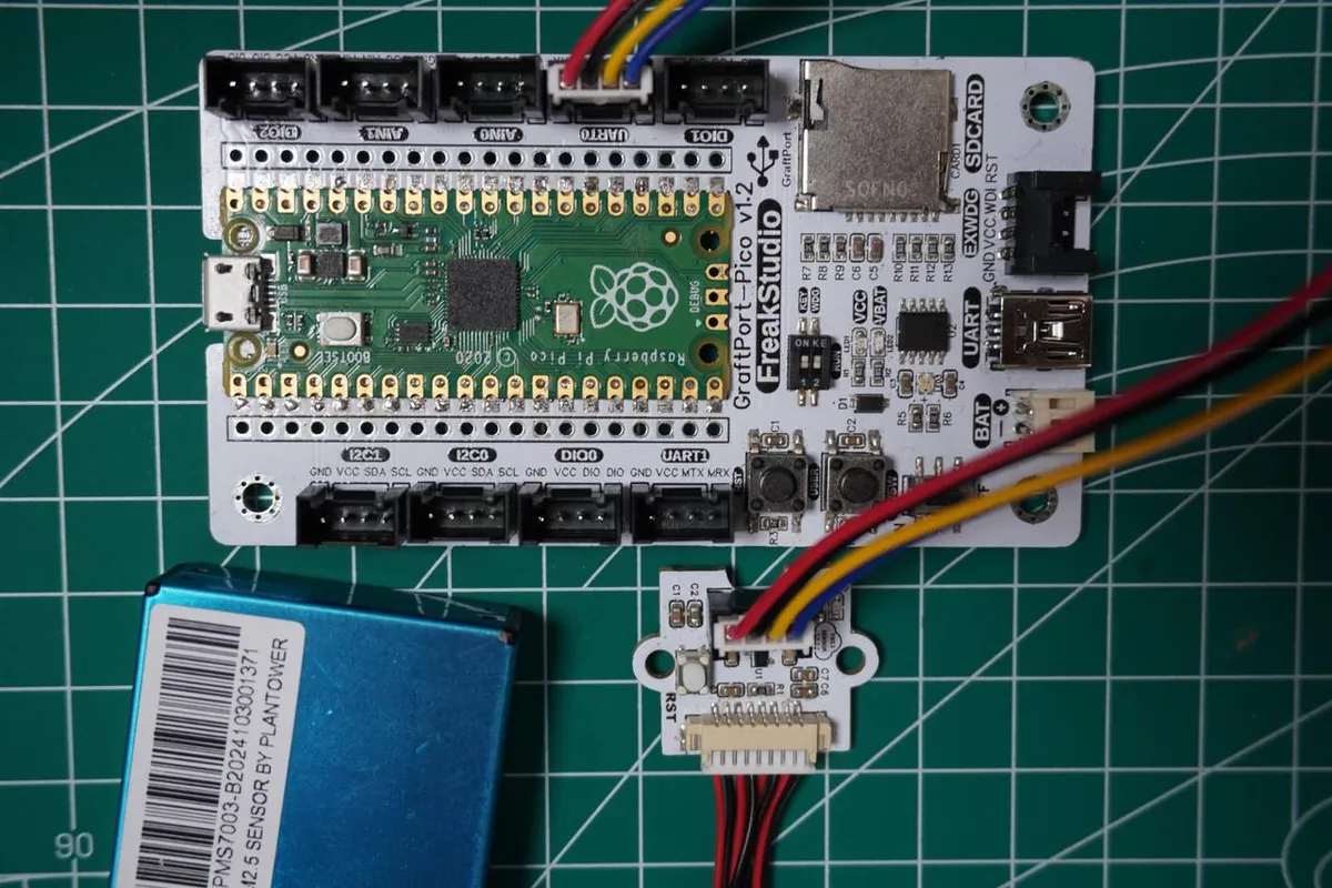
The module connections are shown in the following table:
Development Board Pins | Module Pins | Description |
Pin 16 |
|
|
Pin 17 |
|
|
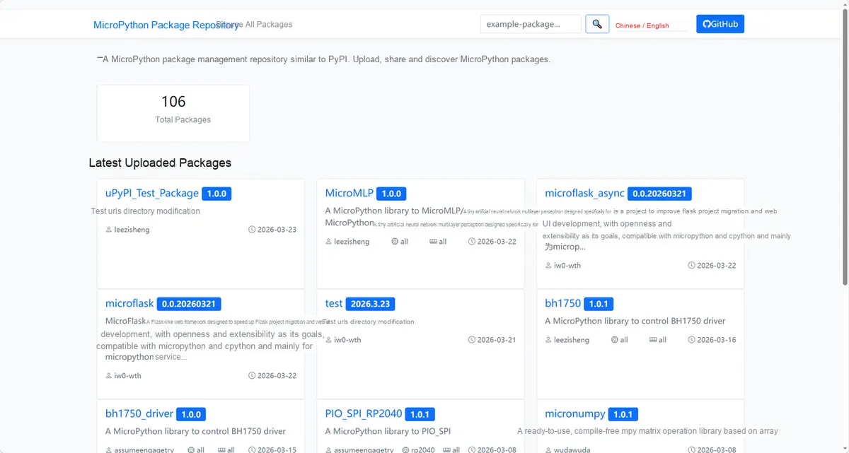
Here, we need to search for the relevant driver packages on uPyPI: https://upypi.net/zh/
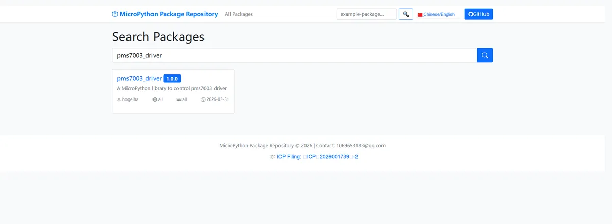
Enter pms7003_driver to search, and the following will be displayed:
Click to copy the local installation command:
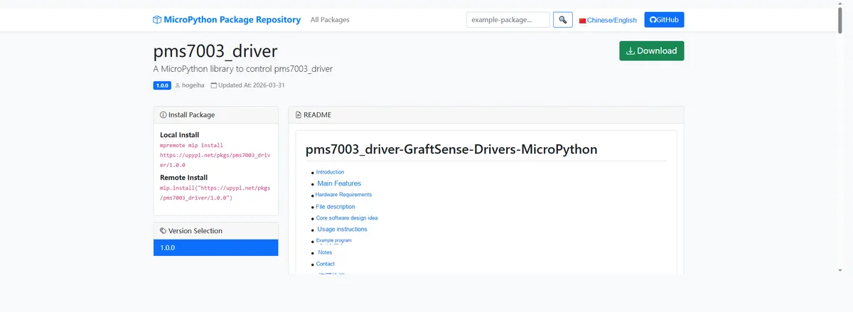
Import the module driver library code via the mip tool. Below are the usage commands for the mpremote tool:
mpremote mip install https://upypi.net/pkgs/pms7003_driver/1.0.0Import the MicroPython driver code for the PMS7003-based particulate matter concentration detection adapter module, then copy the following main.py code into our project:
# Python env   : MicroPython v1.23.0
# -*- coding: utf-8 -*-
# @Time    : 2025/1/10 3:00 PM
# @Author  : hogeiha
# @File    : main.py
# @Description : PMS7003 air quality sensor data reading and AQI calculation program

# ======================================== Import Modules =========================================

# Import the AQI calculation module
from aqi import AQI
# Import the PMS7003 sensor driver module
from pms7003 import Pms7003
# Import the UART and Pin classes from the machine module
from machine import UART,Pin
# Import the time module
import time

# ======================================== Global Variables ============================================


# ======================================== Functions ============================================

def demo_active_mode():
    """
    Demonstrates reading sensor data in active mode
    Args: None

    Raises:
        UartError: UART communication error
        Exception: Other read errors

    Notes: In active mode the sensor outputs data continuously, no wake-up operation is needed

    ==========================================
    Demo sensor data reading in active mode
    Args:None

    Raises:
        UartError: UART communication error
        Exception: Other reading errors

    Notes:Sensor continuously outputs data in active mode, no wake-up required
    """
    print("=== Active Mode: Start reading PMS7003 data ===")

    # Initialize UART0, baud rate 9600, TX pin 16, RX pin 17
    uart0 = UART(0, baudrate=9600, tx=Pin(16), rx=Pin(17))
    # Initialize the PMS7003 sensor object
    sensor = Pms7003(uart=uart0)
    # Wait for the sensor to stabilize
    time.sleep(30)

    while True:
        try:
            # Read the sensor data
            data = sensor.read()
            # Extract the PM2.5 concentration data
            pm25 = data['PM2_5_ATM']
            # Extract the PM10 concentration data
            pm10 = data['PM10_0_ATM']
            # Calculate the air quality index (AQI)
            aqi_value = AQI.aqi(pm25, pm10)

            # Print data separator line
            print("-" * 50)
            # Print the PM2.5 concentration value
            print(f"PM2.5: {pm25} μg/m³")
            # Print the PM10 concentration value
            print(f"PM10 : {pm10} μg/m³")
            # Print the calculated AQI value
            print(f"AQI  : {aqi_value:.1f}")
            # Print data separator line
            print("-" * 50)

        except UartError as e:
            print(f"UART error: {e}")
        except Exception as e:
            print(f"Read failed: {e}")

        # Perform the next read after 2 seconds
        time.sleep(2)

def demo_passive_mode():
    """
    Demonstrates reading sensor data in passive mode
    Args: None

    Raises:
        UartError: UART communication error
        Exception: Other read errors

    Notes: In passive mode the sensor must be woken up before it outputs data; after reading, it can enter sleep mode to reduce power consumption

    ==========================================
    Demo sensor data reading in passive mode
    Args:None

    Raises:
        UartError: UART communication error
        Exception: Other reading errors

    Notes:Sensor needs to be woken up to output data in passive mode, can enter sleep mode after reading to reduce power consumption
    """
    print("=== Passive Mode: Start reading PMS7003 data ===")

    # Initialize UART0, baud rate 9600, TX pin 16, RX pin 17
    uart0 = UART(0, baudrate=9600, tx=Pin(16), rx=Pin(17))
    # Initialize the passive-mode PMS7003 sensor object
    sensor = PassivePms7003(uart=uart0)
    # Wait for the sensor to initialize
    time.sleep(2)

    while True:
        try:
            # Print the wake-up prompt
            print("Waking up sensor...")
            # Wake up the sensor
            sensor.wakeup()
            # Wait for the sensor to respond
            time.sleep(2)

            # Read the sensor data
            data = sensor.read()
            # Extract the PM2.5 concentration data
            pm25 = data['PM2_5_ATM']
            # Extract the PM10 concentration data
            pm10 = data['PM10_0_ATM']
            # Calculate the air quality index (AQI)
            aqi_value = AQI.aqi(pm25, pm10)

            # Print data separator line
            print("-" * 50)
            # Print the PM2.5 concentration value
            print(f"PM2.5: {pm25} μg/m³")
            # Print the PM10 concentration value
            print(f"PM10 : {pm10} μg/m³")
            # Print the calculated AQI value
            print(f"AQI  : {aqi_value:.1f}")
            # Print data separator line
            print("-" * 50)

            # Print the sleep prompt
            print("Putting sensor to sleep...")
            # Put the sensor into sleep mode
            sensor.sleep()

        except UartError as e:
            print(f"UART error: {e}")
        except Exception as e:
            print(f"Read failed: {e}")

        # Take the next reading after 10 seconds
        time.sleep(10)

# ======================================== Custom Classes ============================================


# ======================================== Initialization configuration ===========================================

# Wait for the system to start up and stabilize
time.sleep(3)
print("FreakStudio: PMS7003 sensor system initialized")

# ========================================  Main Program  ============================================

# Main program entry point
if __name__ == "__main__":
    # Run the active mode demo function
    demo_active_mode()
Burn the code, open the terminal, and the output is as follows:
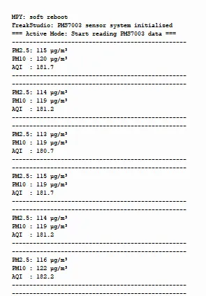
We can see that the code can read in a loop PM concentrations and AQI data.
4. Drivers
pms7003_driver-1.0.0.zip 13 KB
5. BOM & Recommended Alternative Parts
None.
VI. Revision History
Document Version | Date of Revision | Modifier | Modify Content |
v1.0 | 2026-03-25 | Ling Gaoxing | Initialize the document |
v1.0.1 | 2026-04-05 | Li Zisheng | No photos for the homepage have been taken, the production files have not been exported yet, and all other items have been sorted out. |
v1.0.2 | 2026-04-21 | Li Zisheng | The production documents have not been exported yet, while all the rest have been sorted out. |
v1.1 | 2026-04-23 | Xin Ruili | Create an open version of the document, based on the internal document version v1.0.2. |
VII. Relevant Materials
7.1 Chip Datasheet
PMS7003 Particulate Matter Sensor Chinese Manual.pdf 503 KB
7.2 PCB Silkscreen Specific Icons