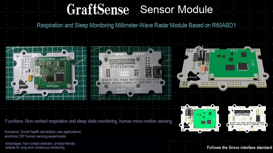
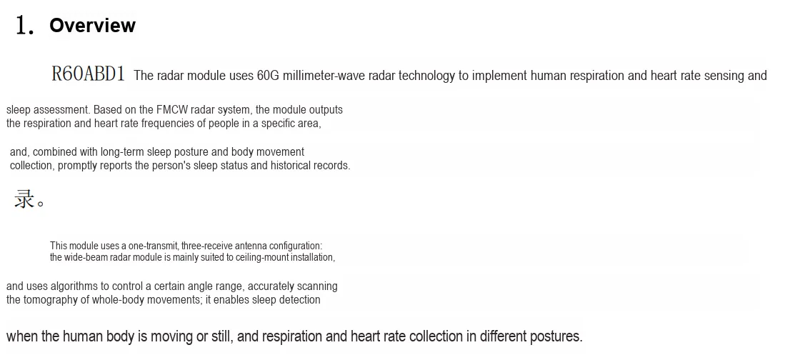
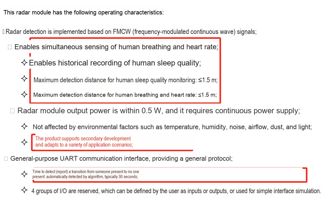
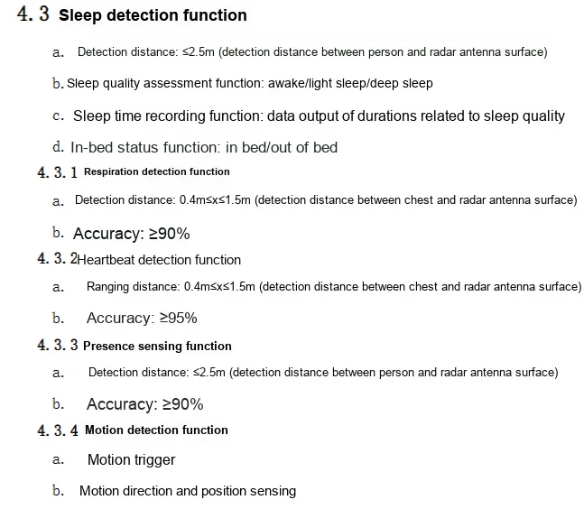
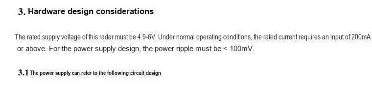
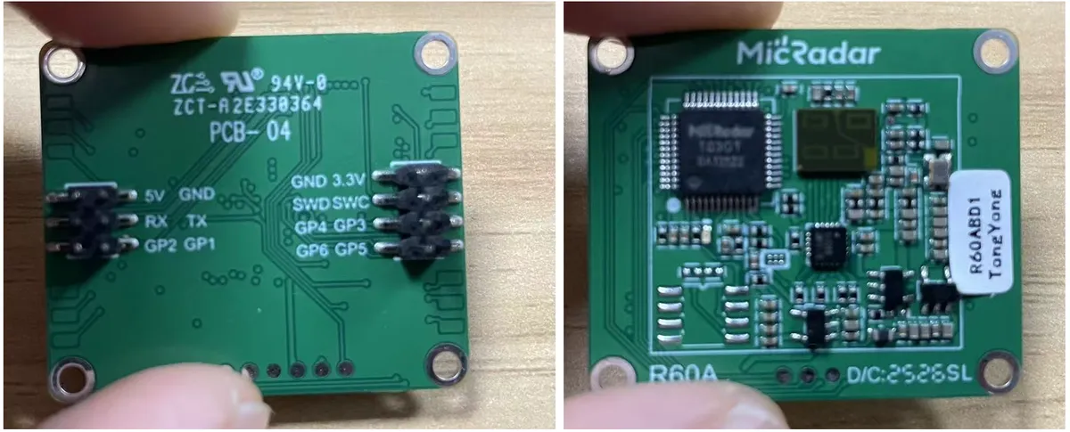
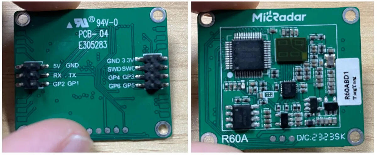
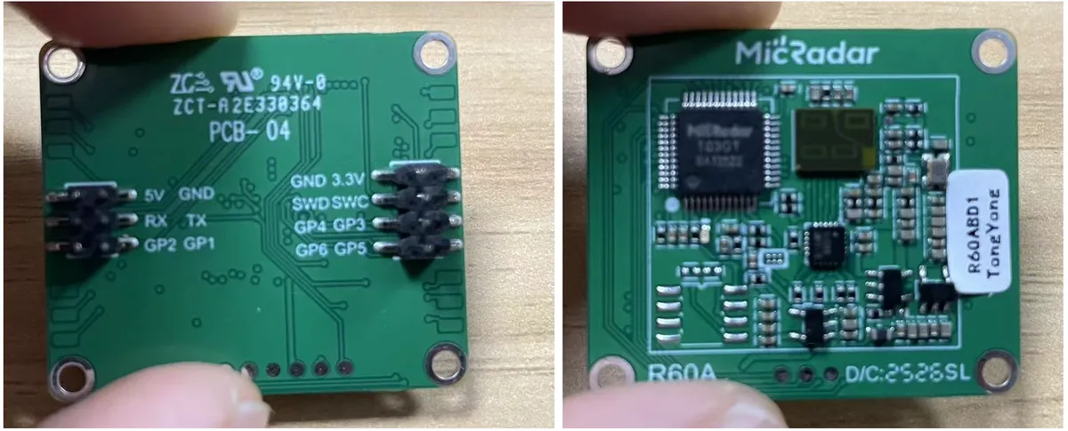
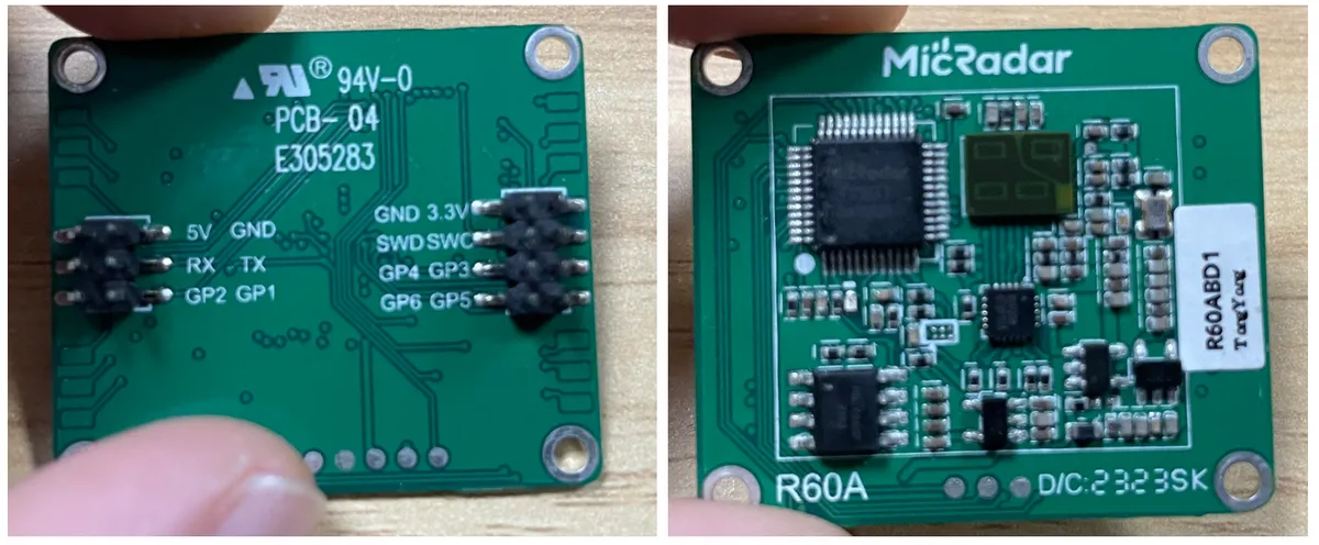
R60ABD1-based millimeter-wave radar module for respiratory and sleep monitoring that adopts FMCW frequency modulated continuous wave technology, can simultaneously sense human respiratory and heart rate within a distance of ≤1.5 meters, record historical sleep quality data, and also realize human presence detection (typical reporting time: 30 seconds).The power supply range of this module is compatible with 5V to 3.3V conversion, and it is equipped with MCU interfaces, power filtering and indicator lights. It is free from interference by environmental factors such as temperature, humidity and noise. With a radar output power of less than 0.5 W and a requirement for long-term power supply, this module is suitable for scenarios including sleep monitoring and health management, and provides a reliable technical solution for non-contact human vital sign monitoring.
II. Introduction to Major Chips
The module adopts R60ABD1 respiratory sleep radar module.
2.1 Chip Overview
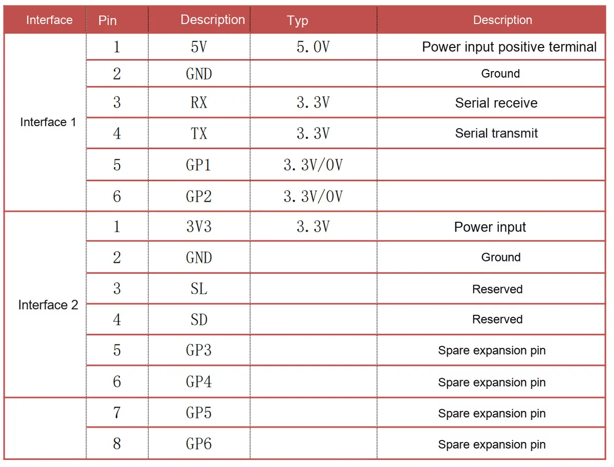
2.2 Pin Definition
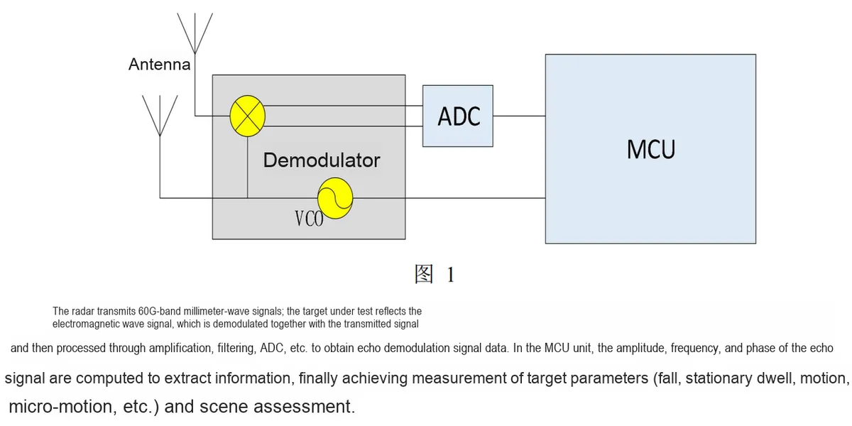
2.3 Functional Block Diagram
2.4 Performance Parameters
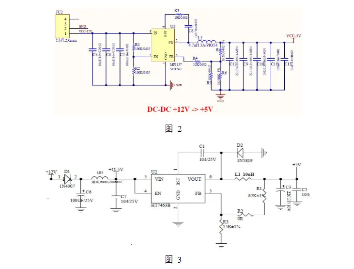
2.5 Reference Circuit
2.6 Chip Configuration
This module is of Plug and Play type, requiring no hardware configuration or software register settings. R60ABD1 performs data interaction with other devices via a serial port for communication.
2.7 Communication Interfaces and Related Protocols
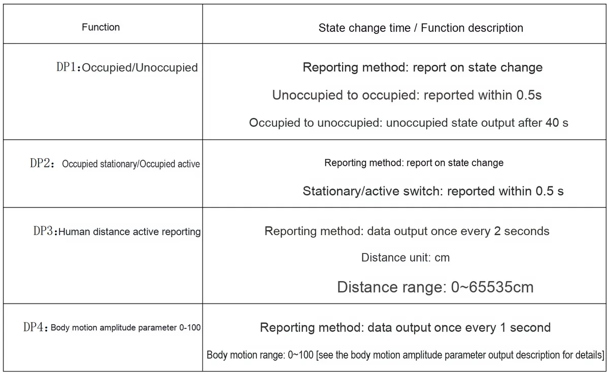
2.7.1 Description of Vital Sign Parameters Actively Posted Back by Radar
Function
Function / data type
Reporting method
State change time / period
Data range / description
DP1
Occupied / unoccupied
Reported on state change
Unoccupied→occupied: ≤0.5s; occupied→unoccupied: about 40s
0=unoccupied, 1=occupied
DP2
Occupied stationary / occupied active
Reported on state change
Stationary↔active: ≤0.5s
0=stationary, 1=active
DP3
Human body distance
Actively reported
Output every 2s
Unit cm, 0~65535
DP4
Body movement amplitude parameter
Actively reported
Output every 1s
0~100
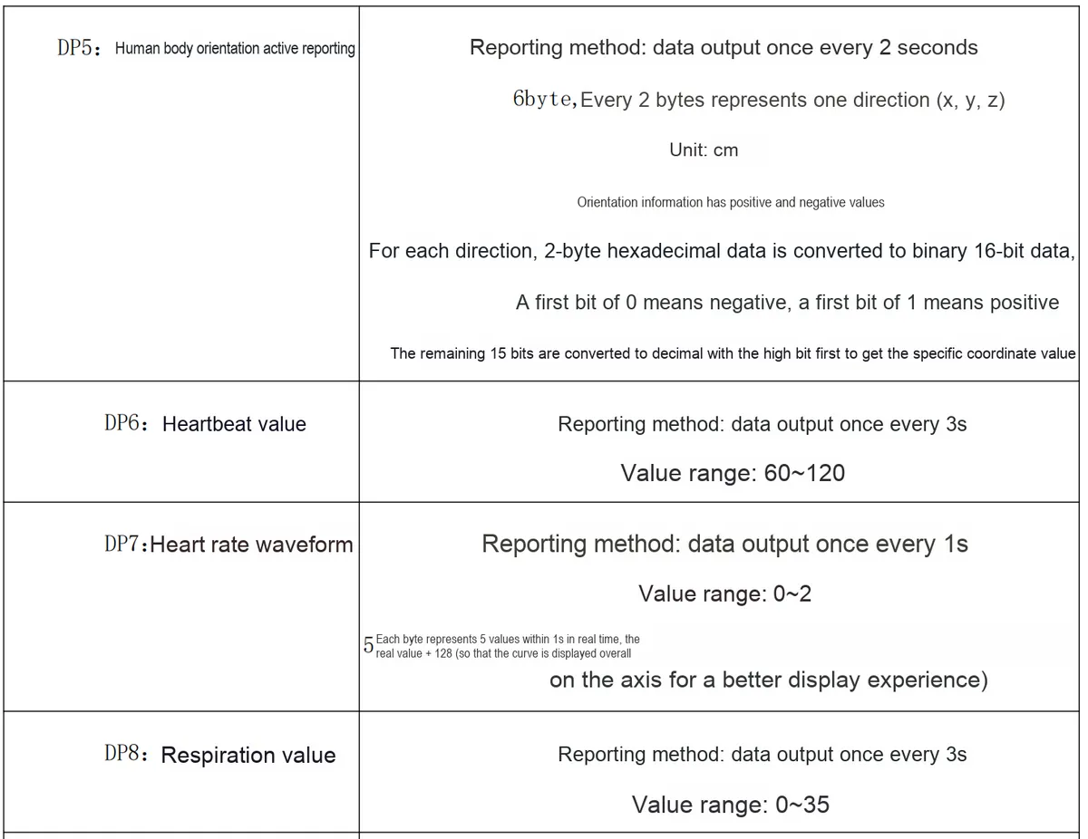
DP5
Human body orientation
Actively reported
Output every 2s
6 bytes (2 bytes each for X, Y, Z axes); the first bit is the sign (0 = negative, 1 = positive), the remaining 15 bits are the coordinate value
DP6
Heartbeat value
Actively reported
Output every 3 s
60~120 bpm
DP7
Heart rate waveform
Actively reported
Output every 1 s (5 bytes)
Range 0-2; data = true value + 128 (centered display)
DP8
Respiration value
Actively reported
Output every 3 s
0-35 breaths/min
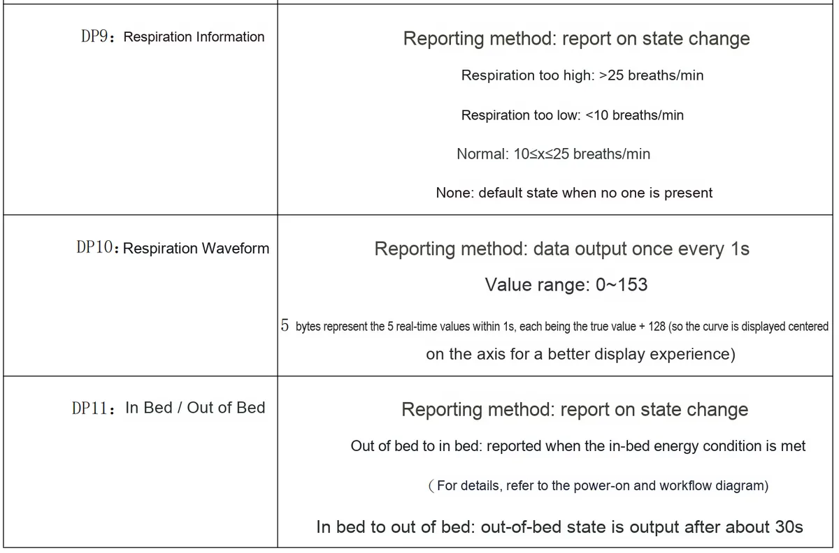
DP9
Respiration information
Reported on state change
Real-time
0 = no one present, 1 = normal (10-25), 2 = too low (<10), 3 = too high (>25)
DP10
Respiration waveform
Actively reported
Output every 1 s (5 bytes)
Range 0-153; data = true value + 128 (centered display)
DP11
Enter bed / leave bed
Reported on state change
Enter bed: reported immediately when conditions are met; leave bed: about 30 s
0 = left bed, 1 = in bed
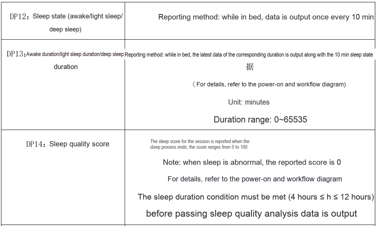
DP12
Sleep state
Actively reported
Output every 10 min while in bed
0 = deep sleep, 1 = light sleep, 2 = awake, 3 = left bed
DP13
Sleep duration (awake/light/deep)
Actively reported
Updated every 10 min while in bed
Range 0-65535 minutes
DP14
Sleep quality score
Actively reported
At the end of the sleep session
0100 points; 0 when abnormal; valid result is output only after 412 h
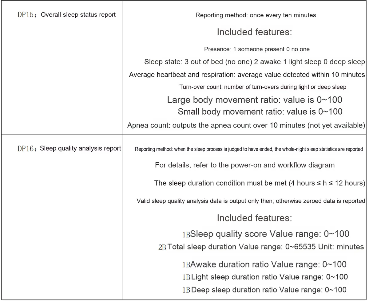
DP15
Comprehensive sleep status
Actively reported
Output once every 10 min
Includes: presence, sleep state, average heartbeat/respiration, number of turnovers, percentage of large/small body movements, number of apnea events (not available yet)
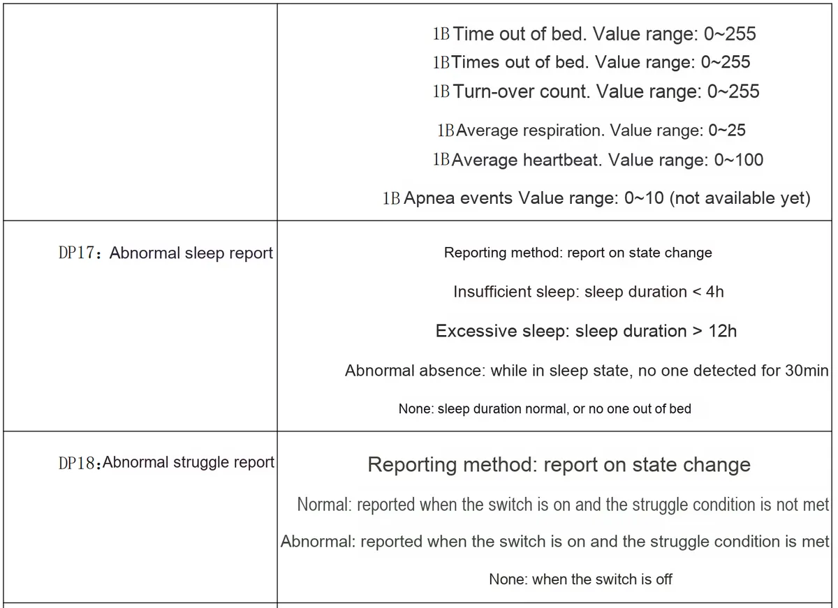
DP16
Sleep quality analysis
Actively reported
Output at the end of sleep
Includes: sleep score, total duration, percentage of awake/light/deep sleep, time/number of times out of bed, number of turnovers, average respiration/heartbeat, number of apnea events (not available yet)
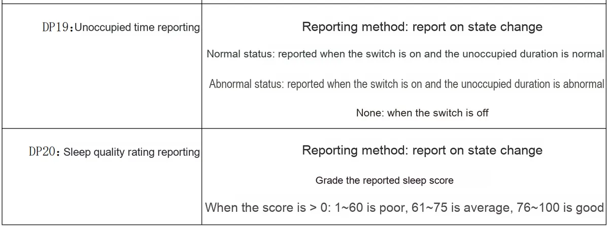
DP17
Sleep abnormality
Reported on state change
Real-time
0 = no abnormality, 1 = too short (<4 h), 2 = too long (>12 h), 3 = abnormal, no one present
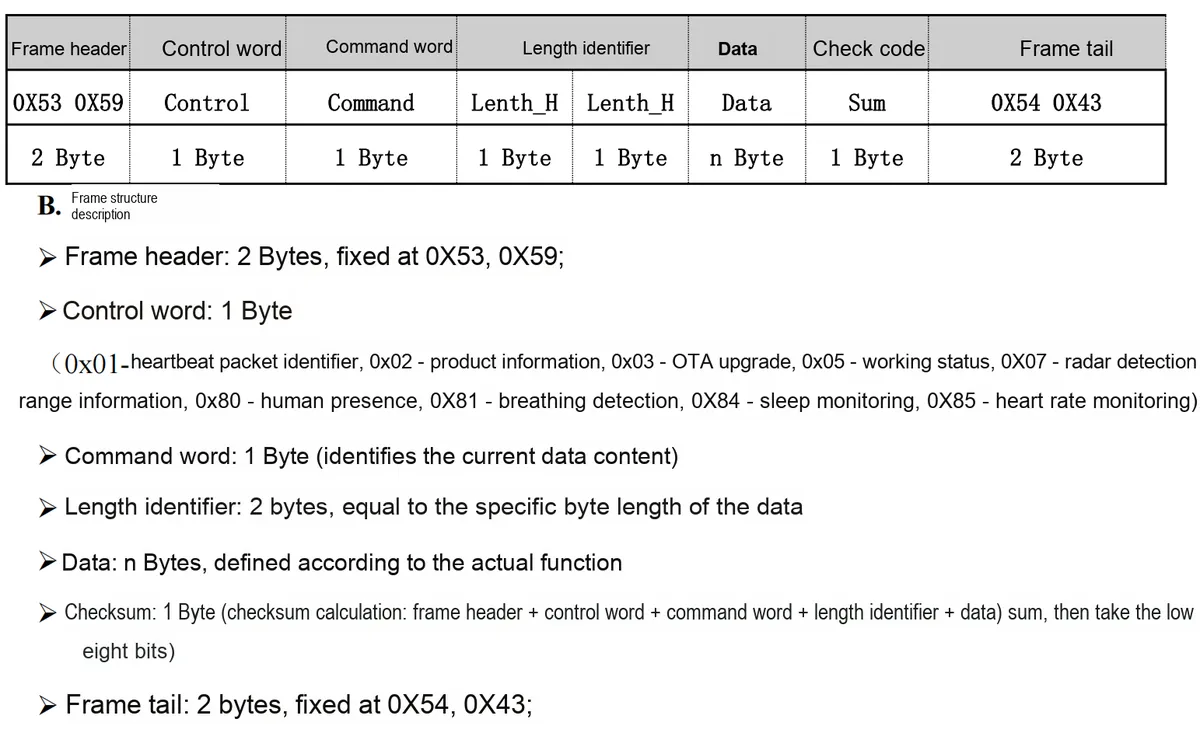
Radar detection range information position out-of-bounds status query: 53 59 07 87 00 01 0F 4A 54 43
Response sample: 53 59 07 87 00 01 00 3B 54 43
2.7.4 Query and Setting of Human Presence Command Information
Note: All information related to human presence can only be parsed based on actively reported data after the human presence function is enabled.
On the following version numbers, the usage logic for enabling or disabling the human presence function differs from that on the G60SM1SYv010107 version:
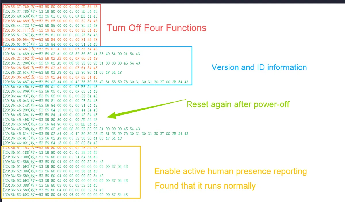
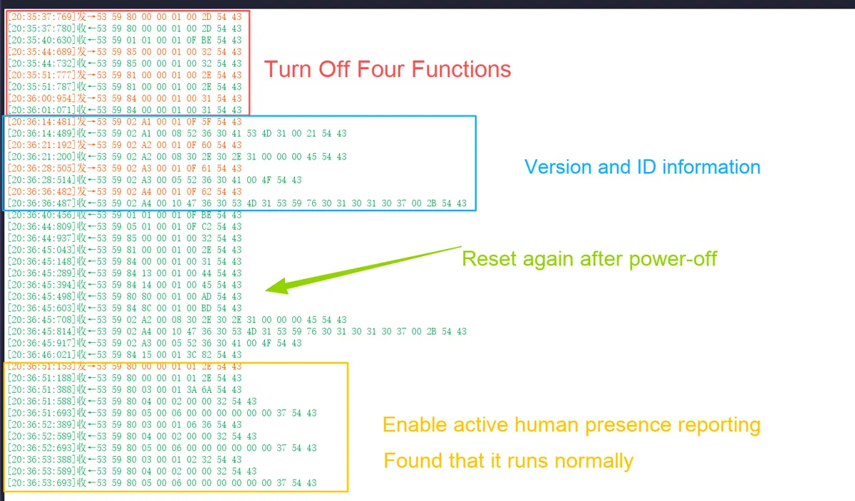
On the new firmware version (G60SM1SYv010309), an abnormal operation sequence has been identified:
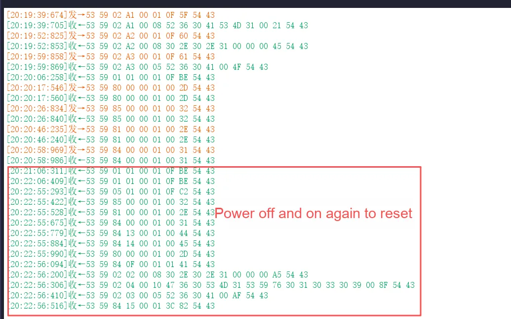
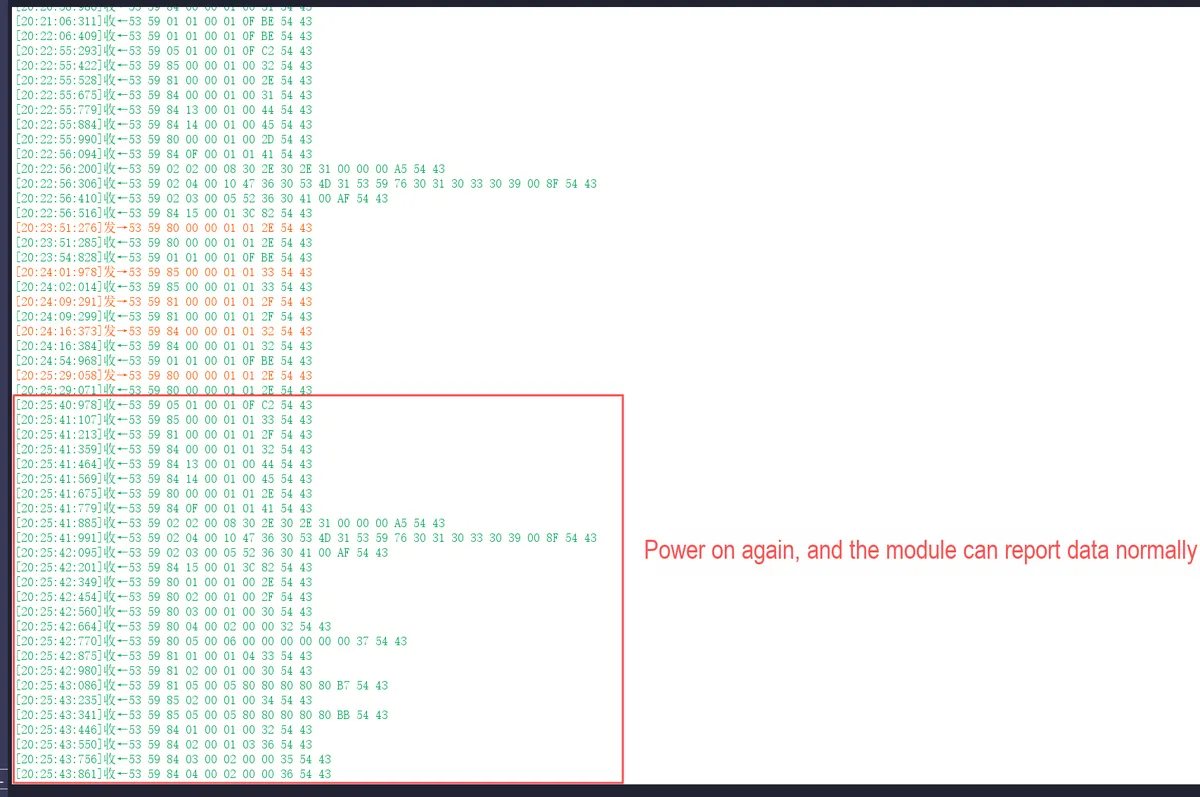
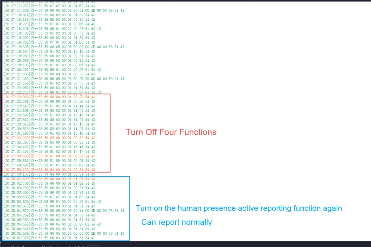
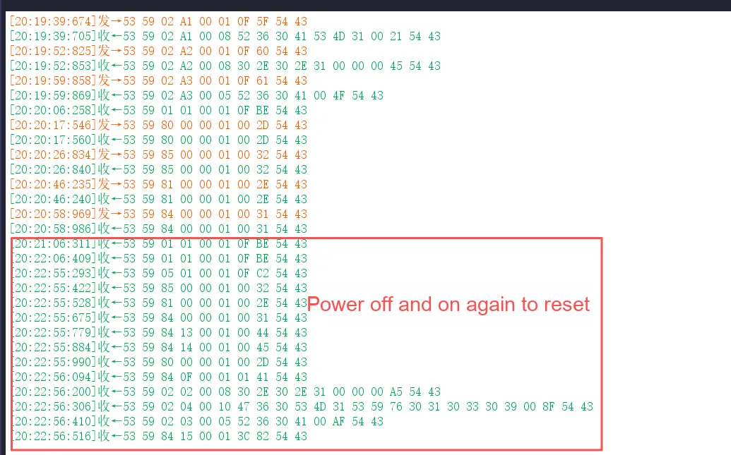
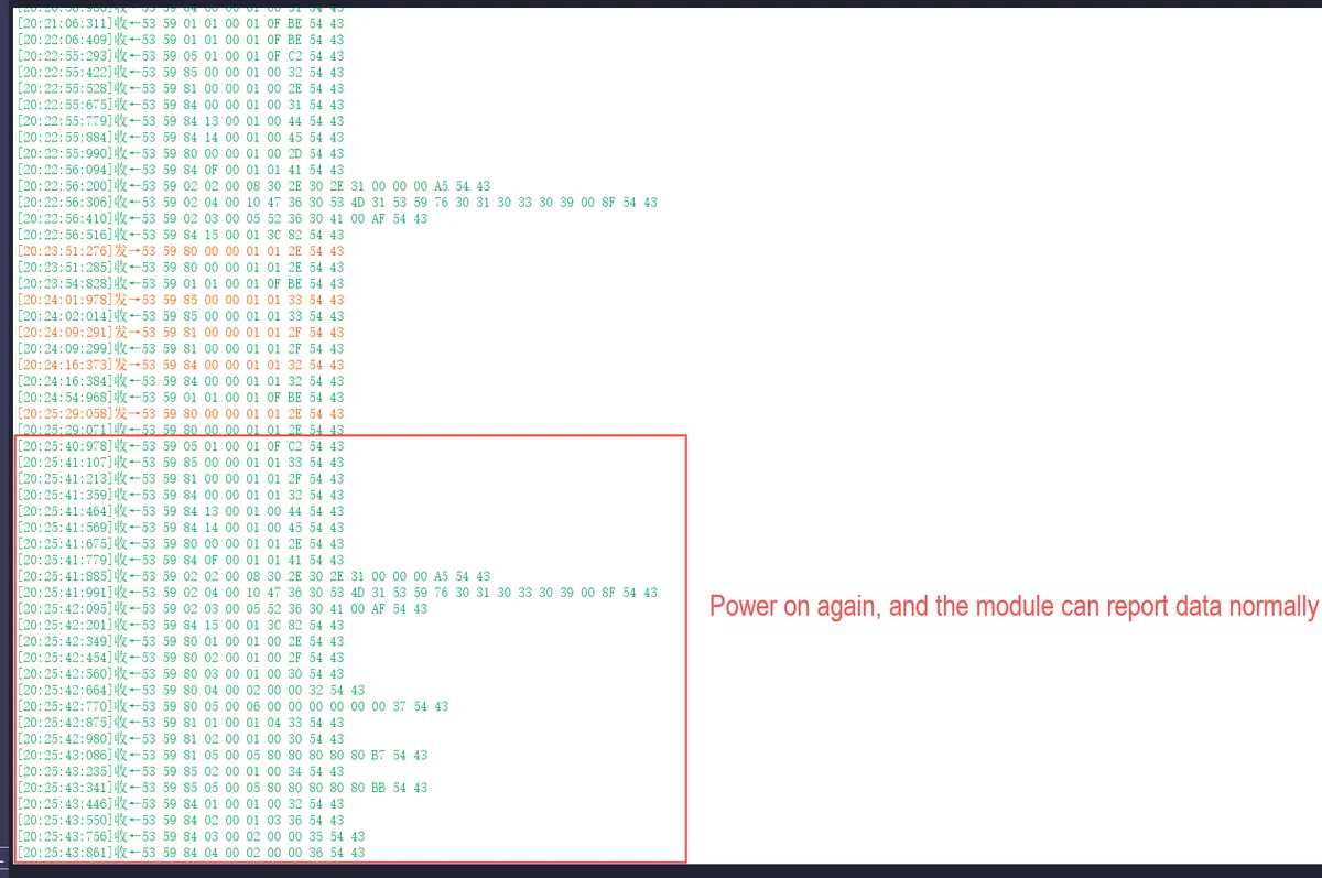
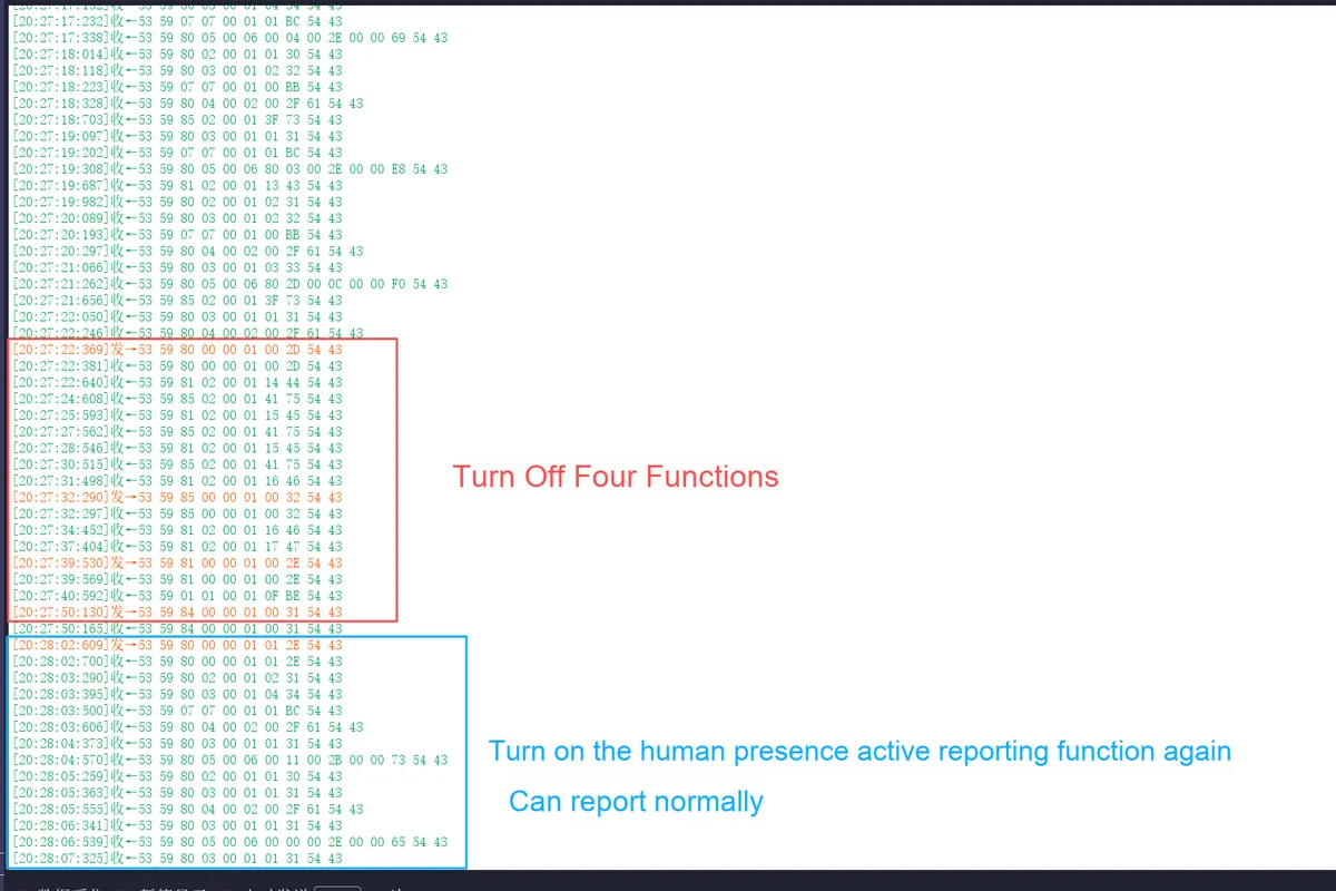
The N-th operation: After sequentially disabling the active reporting of the four functions of human presence, heart rate, respiration and sleep, power off the millimeter-wave radar module and then power it on again.
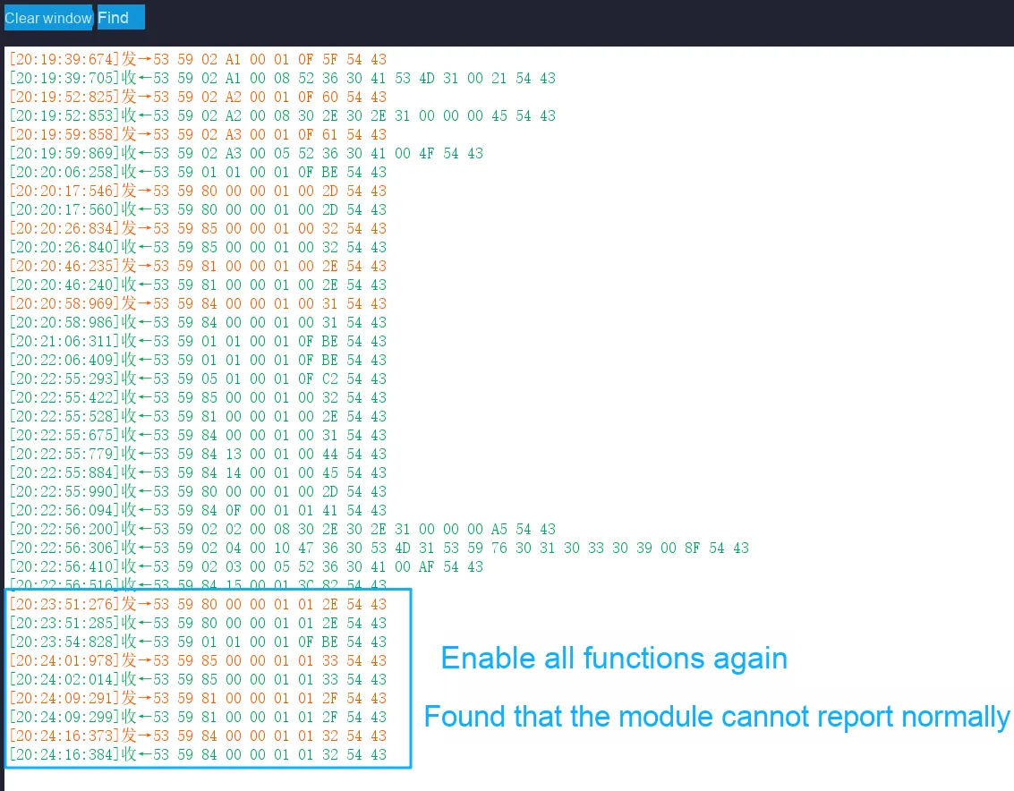
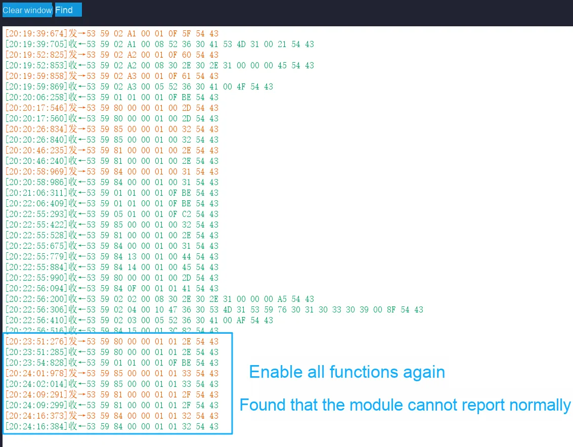
The (N+ 1)-th operation: After the module is restarted, if any single one of its functions is enabled separately at this point, no corresponding active reported data can be received.
The (N+ 2)-th operation: Enable all active reporting functions of the four features, and then power off and restart the module again. After that, all active reporting functions resume normal operation, and during this power-on cycle, any expected response can be obtained no matter a single function is enabled or disabled.
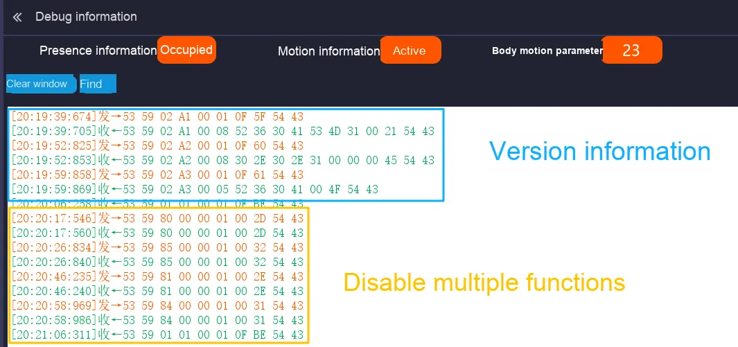
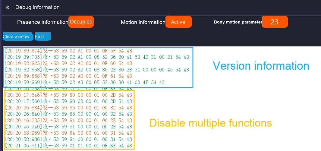
The following is the testing procedure conducted on the new firmware (G60SM1SYv010309):
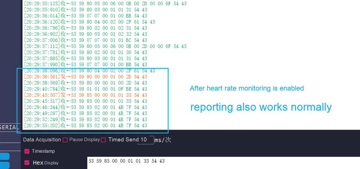
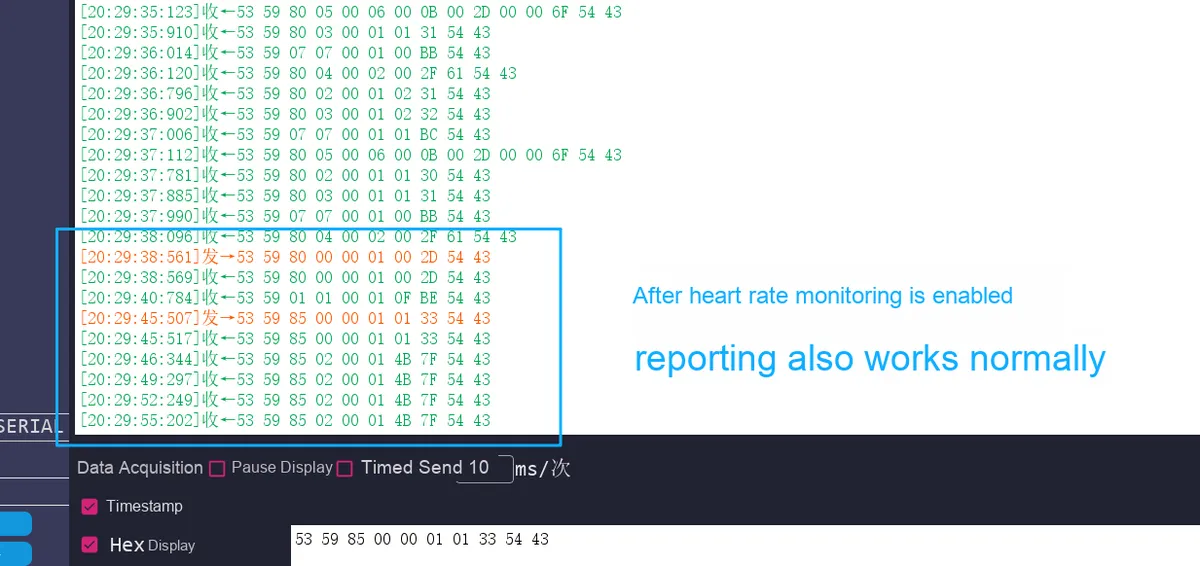
Below are the same tests conducted on the old firmware version (G60SM1SYv010107):
For a summary of related issues, please refer to Section 2.7.8
Enable or disable the human presence detection function
Enable human presence function: 53 59 80 00 00 01 01 2E 54 43
2.7.5 Query and Setting of Heart Rate Monitoring Command Information
Note that in actual tests, the heart rate waveform reporting switch setting and heart rate waveform reporting switch query in the commands related to heart rate monitoring information are unavailable on certain versions, and the relevant version numbers are as follows:
On the new firmware version (G60SM1SYv010309), an abnormal operation sequence has been identified:
The N-th operation: After sequentially disabling the active reporting of the four functions of human presence, heart rate, respiration and sleep, power off the millimeter-wave radar module and then power it on again.
The (N+ 1)-th operation: After the module is restarted, if any single one of its functions is enabled separately at this point, no corresponding active reported data can be received.
The (N+ 2)-th operation: Enable all active reporting functions of the four features, and then power off and restart the module again. After that, all active reporting functions resume normal operation, and during this power-on cycle, any expected response can be obtained no matter a single function is enabled or disabled.
Note: Among the heart rate monitoring information, only the heart rate waveform can be obtained through query-response inquiry when the heart rate waveform reporting switch is turned off (with the heart rate monitoring function enabled), while all other heart rate monitoring information (such as heart rate value) can only be parsed from the actively reported data after the heart rate monitoring function is turned on.
Enable or disable the heart rate monitoring function
Response example: 53 59 85 85 00 05 C1 BE AA 90 8A FE 54 43
2.7.6 Query and Setting of Respiratory Monitoring Instruction Information
Note that, except for the respiratory waveform in the respiratory monitoring information which can be obtained through query-response inquiry when the respiratory waveform reporting switch is turned off (while the respiratory monitoring function is enabled), all other respiratory monitoring information (such as respiratory values) can only be parsed based on actively reported information after the respiratory monitoring function is turned on.
The usage logic for enabling/disabling the breathing monitoring function on the following version numbers differs from that on the G60SM1SYv010107 version:
On the new firmware version (G60SM1SYv010309), an abnormal operation sequence has been identified:
The N-th operation: After sequentially disabling the active reporting of the four functions of human presence, heart rate, respiration and sleep, power off the millimeter-wave radar module and then power it on again.
The (N+ 1)-th operation: After the module is restarted, if any single one of its functions is enabled separately at this point, no corresponding active reported data can be received.
The (N+ 2)-th operation: Enable all active reporting functions of the four features, and then power off and restart the module again. After that, all active reporting functions resume normal operation, and during this power-on cycle, any expected response can be obtained no matter a single function is enabled or disabled.
Shallow and Slow Breathing Interpretation Setting (Default Value 0x0A): The value ranges from 10 to 20 (0x0A to 0x14); other values can be used as replacement data fields, and the checksum needs to be recalculated.
On the new firmware version (G60SM1SYv010309), an abnormal operation sequence has been identified:
The N-th operation: After sequentially disabling the active reporting of the four functions of human presence, heart rate, respiration and sleep, power off the millimeter-wave radar module and then power it on again.
The (N+ 1)-th operation: After the module is restarted, if any single one of its functions is enabled separately at this point, no corresponding active reported data can be received.
The (N+ 2)-th operation: Enable all active reporting functions of the four features, and then power off and restart the module again. After that, all active reporting functions resume normal operation, and during this power-on cycle, any expected response can be obtained no matter a single function is enabled or disabled.
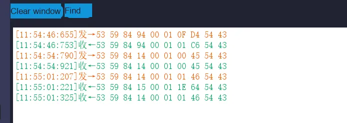
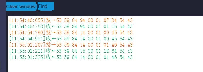
On the following version numbers, a deviation between the actual observed communication sequence and the manual specification was noted when attempting to enable the unattended timing function!!!
Article 1:53 59 84 15 00 01 1E 64 54 43 (This is a response to the command word 0x15 —— "Unmanned Duration Query", and the data 1E indicates that the duration is 30 minutes)
Article 2:53 59 84 14 00 01 01 46 54 43 (This is the correct acknowledgment frame for the setting command as described in the manual)
This behavior does not conform to the typical "command-response" mode; when the unattended timing function is enabled, the firmware automatically triggers a query operation for the unattended timing duration internally.
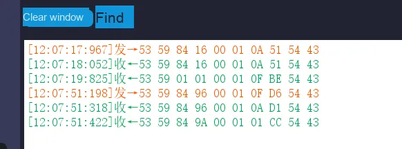
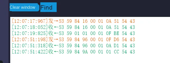
On the following version number, when attempting to test the sleep deadline query function, the actual communication sequence observed deviates from the description in the manual!!!
After setting the sleep timeout duration, an inconsistency is observed between the actual communication sequence during query operations and the description in the manual:
First response: 53 59 84 96 00 01 0A D1 54 43 (expected query response, the data 0A indicates that the sleep timeout duration is 10 minutes).
Second response: 53 59 84 9A 00 01 01 CC 54 43 (unexpected response, corresponding to command word 0x9A, i. e. the response to "struggle status interpretation query", the data 01 indicates medium sensitivity).
After the sleep deadline query, the device additionally returned a response frame of "struggle state interpretation", while the host did not send this query command.
Bed entry/exit status query: 53 59 84 81 00 01 0F C1 54 43
In the actual testing process, we have identified the following issues that require attention in the subsequent driver code development. I have documented the details of each issue and the corresponding specific version numbers here.
2.7.8.1 After disabling the four active reporting functions and restarting the device, enabling any single function individually yields no data response
On the new firmware version (G60SM1SYv010309), an abnormal operation sequence has been identified:
The N-th operation: After sequentially disabling the active reporting of the four functions of human presence, heart rate, respiration and sleep, power off the millimeter-wave radar module and then power it on again.
The (N+ 1)-th operation: After the module is restarted, if any single one of its functions is enabled separately at this point, no corresponding active reported data can be received.
The (N+ 2)-th operation: Enable all active reporting functions of the four features, and then power off and restart the module again. After that, all active reporting functions resume normal operation, and during this power-on cycle, any expected response can be obtained no matter a single function is enabled or disabled.
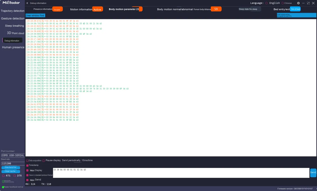
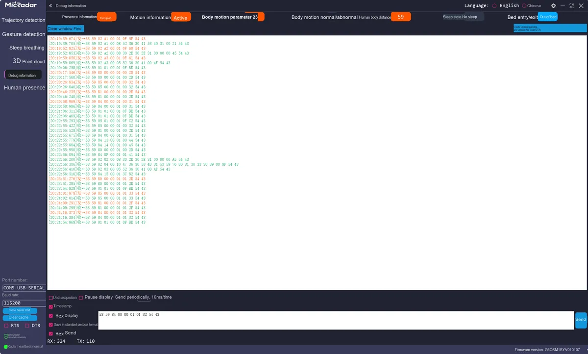
The following is the testing procedure conducted on the new firmware (G60SM1SYv010309):
Below are the same tests conducted on the old firmware version (G60SM1SYv010107):
It can be seen that when all active reporting functions are disabled, the module fails to properly initialize its finite-state machine or configuration registers during the power-off and restart process, causing the system to enter an abnormal "silent" state of functions.
Here, the author speculates that the root cause may stem from a flaw in the firmware's state management logic. The detailed analysis is as follows:
Configuration storage and loading exception:
Speculation: The enable status flag of the device may be stored in non-volatile memory. When all functions are turned off, what is stored may be a special "all-off" status value. When the module loads this configuration at the next startup, the firmware may incorrectly parse this status as "do not perform any reporting" instead of "wait for user instructions", thus blocking all reporting channels.
Corroboration: Only after "fully enabling all the options" again and restarting the system, when the stored status is updated, can the system return to normal. This indicates that the correct configuration was successfully loaded after the second restart.
Functional finite-state machine deadlock:
Speculation: Each reporting function may share a common enable logic or hardware resource. When all functions are disabled, this logic may erroneously enter a dormant or locked state. At this point, enabling a single function individually via instructions cannot effectively trigger the unlocking of the finite-state machine. However, enabling all functions simultaneously sends a sufficiently strong "global wake-up" signal that resets the entire finite-state machine.
Underlying driver or Middleware vulnerabilities:
Speculation: There may be a boundary condition vulnerability in the underlying driver or Middleware that manages the core functions of the radar sensor. When it detects that no active reporting functions require servicing, it may completely shut down Data Acquisition or interrupt service routines. Reactivating this acquisition process requires a higher-level initialization command (i. e., "enable all") rather than a switch command for a single function.
2.7.8.2 The response when the unmanned timing function is enabled is inconsistent with that described in the manual
On the new firmware version (G60SM1SYv010309), an abnormal operation sequence has been identified. The version information is as follows:
Article 1:53 59 84 15 00 01 1E 64 54 43 (This is a response to the command word 0x15 —— "Unmanned Duration Query", and the data 1E indicates that the duration is 30 minutes)
Article 2:53 59 84 14 00 01 01 46 54 43 (This is the correct acknowledgment frame for the setting command as described in the manual)
This behavior does not conform to the typical "command-response" mode; when the unattended timing function is enabled, the firmware automatically triggers a query operation for the unattended timing duration internally.
2.7.8.3 Setting the sleep timeout duration results in inconsistent response with the manual description
On the new firmware version (G60SM1SYv010309), an abnormal operation sequence was detected, with the version details as follows:
The problem is as follows: after setting the sleep timeout duration, an inconsistency is observed between the actual communication sequence during the query operation and the description in the manual:
First response: 53 59 84 96 00 01 0A D1 54 43 (expected query response, the data 0A indicates that the sleep timeout duration is 10 minutes).
Second response: 53 59 84 9A 00 01 01 CC 54 43 (unexpected response, corresponding to command word 0x9A, i. e. the response to "struggle status interpretation query", the data 01 indicates medium sensitivity).
After the sleep deadline query, the device additionally returned a response frame of "struggle state interpretation", while the host did not send this query command.
2.8 PCB Routing Precautions
III. Circuit Engineering
3.1 Circuit Source Engineering
To obtain the source project of the circuit, please follow the official account [Freak Embedded]
3.2 Module Usage Instructions
The schematic diagram of this module is shown below:
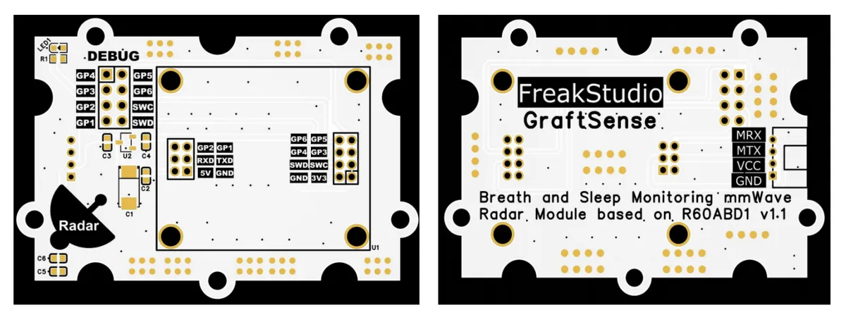
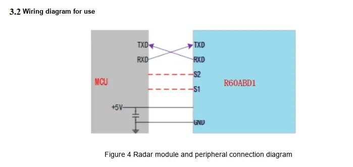
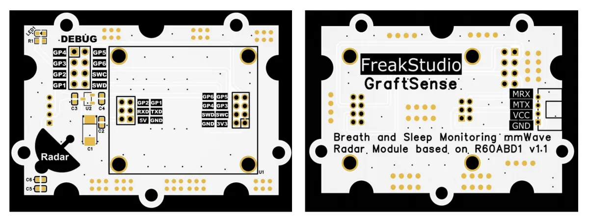
The MRX (corresponding to the UART RXD pin of the MCU) of this module is actually connected to the R60ABD1TXD pin, and the MTX (corresponding to the UART TXD pin of the MCU) is actually connected to the R60ABD1RXD pin; this is because UART serial communication follows the "cross-transmit-receive" rule — the transmit terminal (TX) of both communication parties needs to be connected to the receive terminal (RX) of the counterpart, and this design ensures correct bidirectional UART serial data transmission between the MCU and R60ABD1.
It is particularly important to note that when using this module, MRX is directly connected to the UART RXD of the MCU, and MTX is directly connected to the UART TXD of the MCU. Do not cross-connect them under any circumstances.
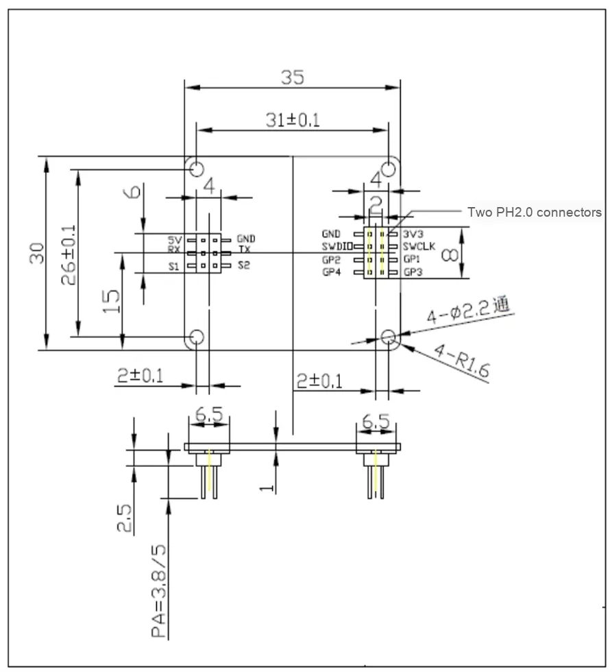
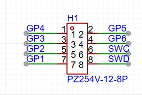
This module leads out external expansion interfaces GP1 - GP6, SWC and SWD to facilitate subsequent function development and firmware upgrade. It should be noted that when soldering 2.54 header pins to the DEBUG interface, they need to be reversely connected to the back to avoid interference with the radar module.
And please note the following when using it:
3.3 Application Experiment
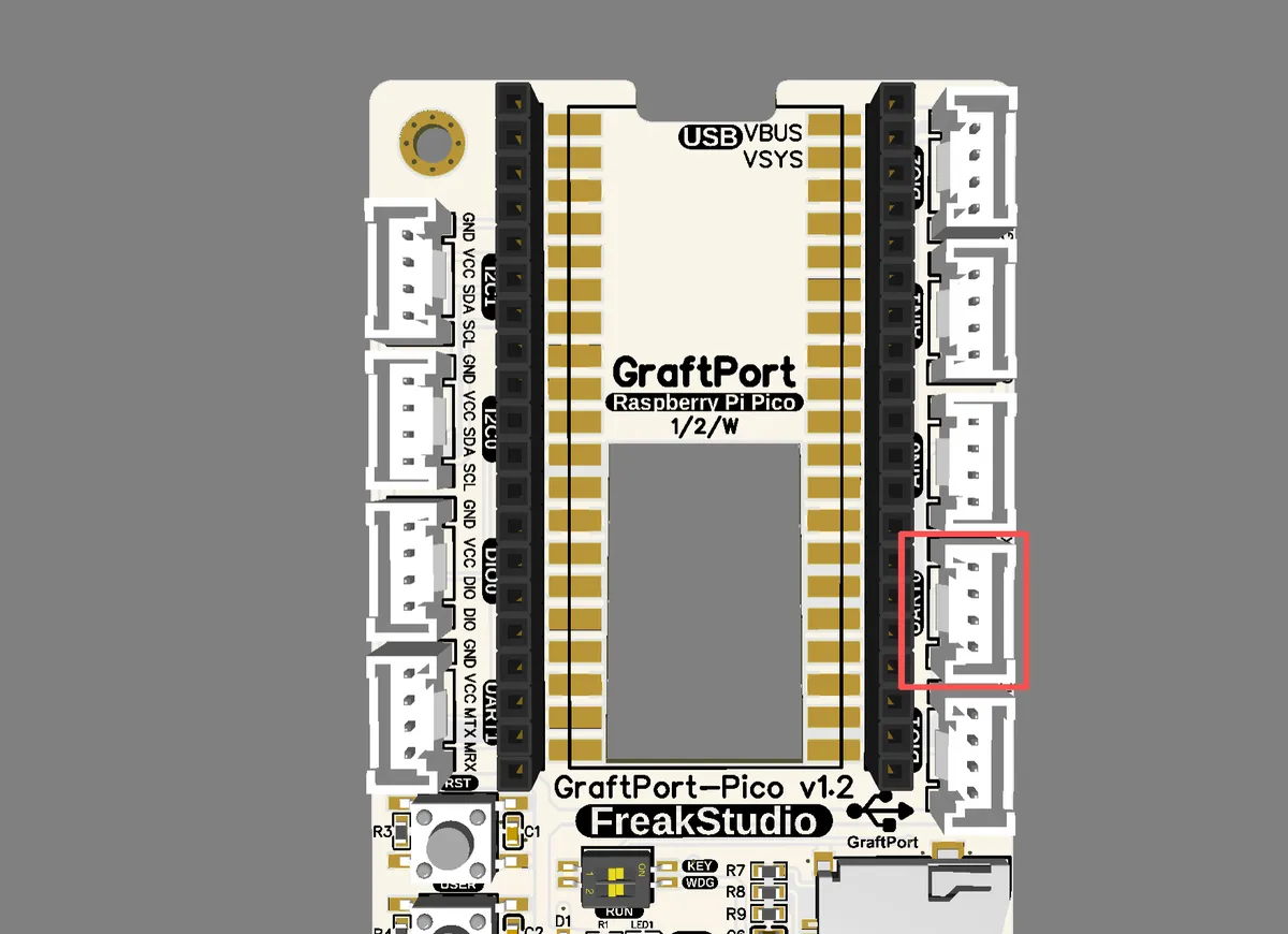
Here, we use the GraftPort-RP2040 development board for testing, and connect the R60ABD1-based millimeter-wave radar module for respiratory and sleep monitoring to communicate with the main controller via the UART interface.
Here, we first use the HY2.0-4P cable to connect the module to the GraftPort-RP2040 development board's UART0 interface:
The module connections are shown in the table below:
Development Board Pins
Module Pins
Description
Pin 16
MTX
UART data transmission line, corresponding to the transmit pin of the development board
Pin 17
MRX
UART data transmission line, corresponding to the receiving pin of the development board
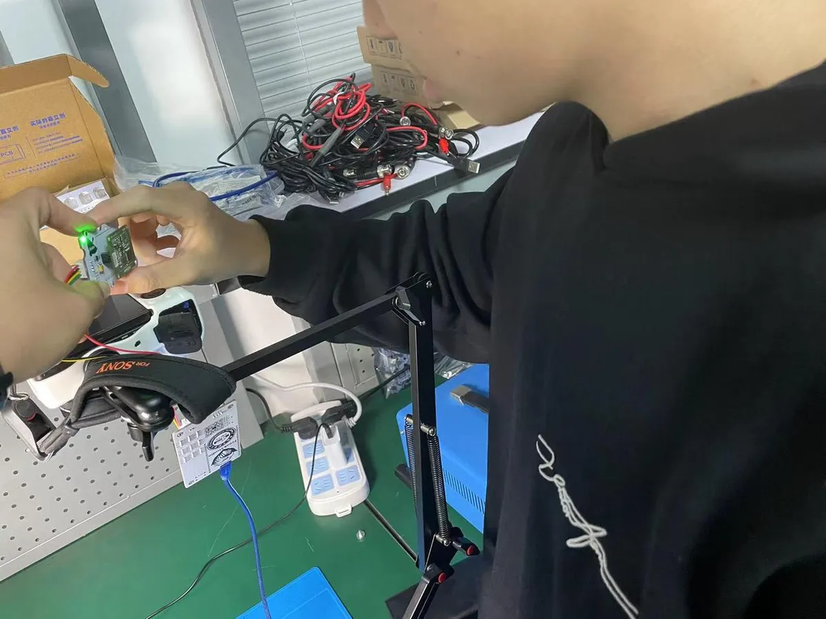
When in use, place the module 20 centimeters directly in front of your chest:
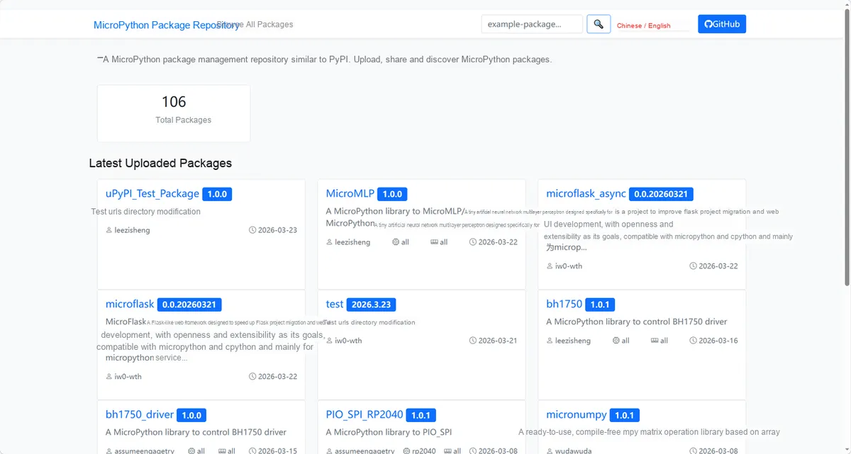
Here, we need to search for the relevant driver packages on uPyPI: https://upypi.net/zh/
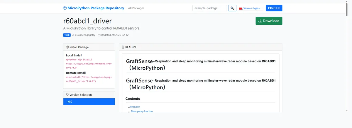
Enter r60abd1_driver to search, and the following will be displayed:
Click to copy the local installation command:
Here, we can use the mip tool to import module driver library code. The following are the usage commands for the mpremote tool: