Contents
- I. Module Introduction
- II. Introduction to Major Chips
- 2.1 Chip Overview
- 2.2 Pin Definition
- 2.3 Functional Block Diagram
- 2.4 Performance Parameters
- 2.5 Reference Circuit
- 2.6 Chip Configuration
- 2.7 Communication Interfaces and Related Protocols
- 2.8 PCB Routing Precautions
- III. Circuit Engineering
- 3.1 Circuit Source Engineering
- 3.2 Module Usage Instructions
- 3.3 Application Experiment
- IV. Drivers
- 5. BOM & Recommended Alternative Parts
- VI. Revision History
- VII. Relevant Materials
- 7.1 Chip Datasheet
- 7.2 Unique Icons for PCB Silkscreen
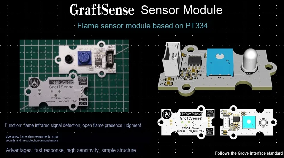
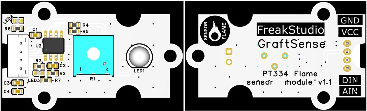
I. Module Introduction
The flame sensor module based on PT334 takes PT334-6B as the core sensing element, is equipped with circuits including the LM393 comparator, operates on a + 5V power supply, and can simultaneously output digital signals (DIN) and analog signals (AIN). It can effectively detect flames, is easy to interface with devices such as microcontrollers, and is suitable for flame detection application scenarios.
II. Introduction to Major Chips
2.1 Chip Overview
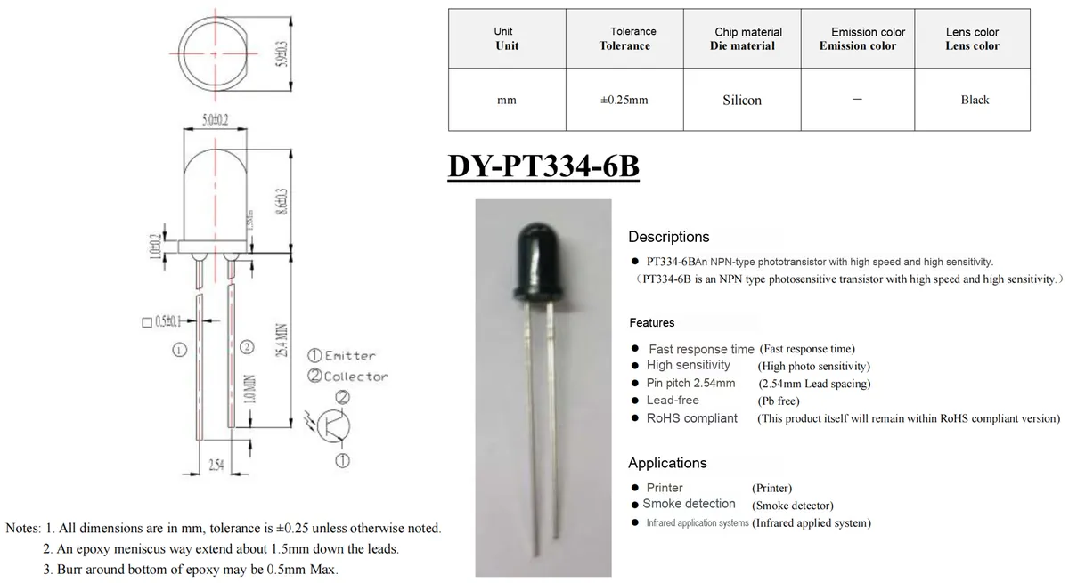
PT334-6B is a high-speed, high-sensitivity NPN phototransistor encapsulated in black epoxy resin, which is sensitive to infrared radiation and can be applied in infrared application systems, cameras, printers and other devices.
2.2 Pin Definition
2.3 Functional Block Diagram
None.
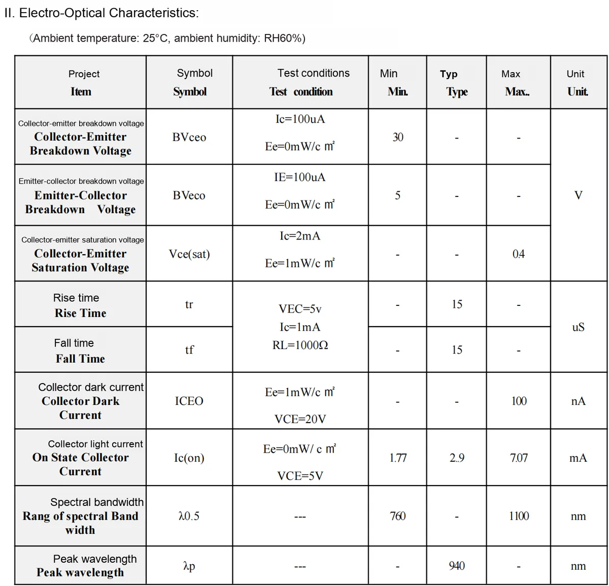
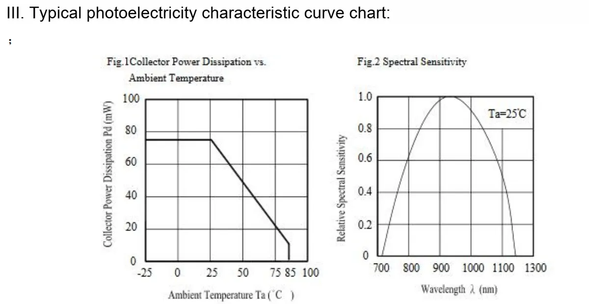
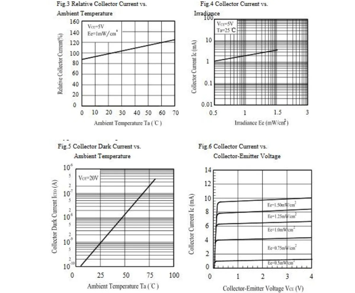
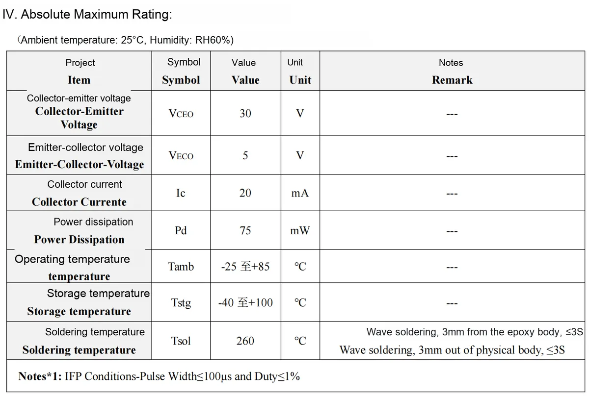
2.4 Performance Parameters
2.5 Reference Circuit
None.
2.6 Chip Configuration
None.
2.7 Communication Interfaces and Related Protocols
None.
2.8 PCB Routing Precautions
None.
III. Circuit Engineering
3.1 Circuit Source Engineering
To obtain the source project of the circuit, please follow the official account [Freak Embedded]
3.2 Module Usage Instructions
The schematic diagram of this module is shown below:
SCH_Flame Sensor Module Based on PT334_v1.1_2025-10-09.pdf 2.3 MB
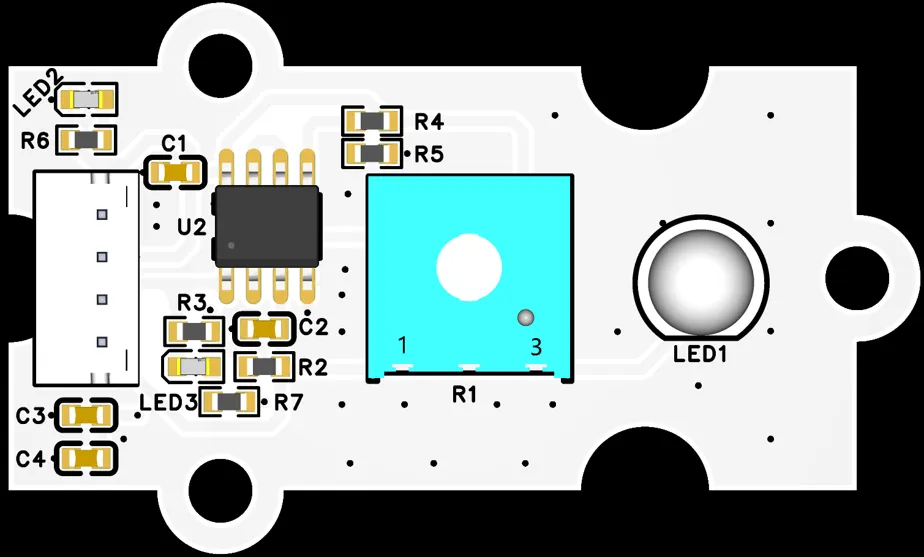
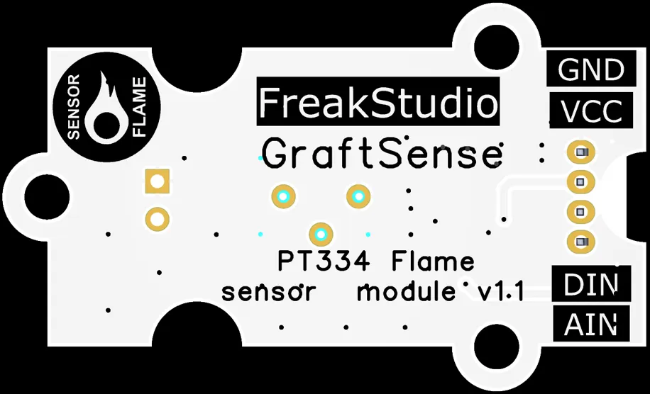
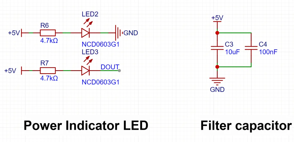
It also features a dual indicator design: the power indicator (LED2) remains steadily on to indicate the module is powered on; the flame indicator (LED3) lights up to indicate that flame is detected.
This module adopts digital output DIN: which can output the flame detection result in the form of high and low levels. When a flame is detected, after being compared with the reference voltage by the LM393 comparator, the DIN terminal will output a low level; otherwise, it will output a high level.
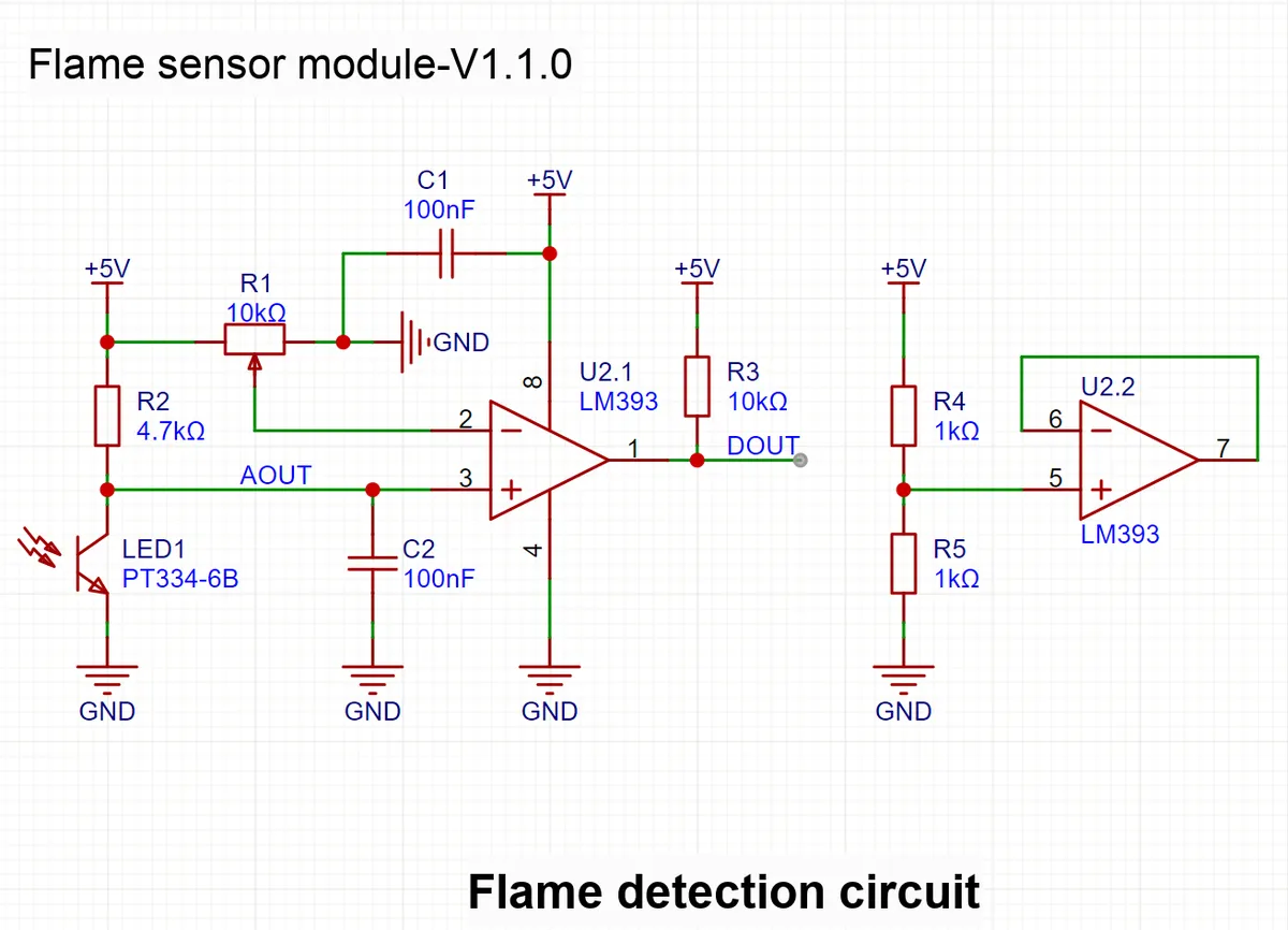
The core circuit consists of a flame sensor probe and LM393 comparator:
- Reference voltage terminal (inverting input terminal, Pin 2): A voltage divider circuit is formed by the adjustable resistor
R1(10kΩ), the+ 5Vpower supply and ground, and adjustingR1allows setting the threshold voltage for flame detection. - Signal Input / Comparison Terminal (Non-inverting Input Terminal, Pin 3): Connect to the analog output (
AOUT) of the flame photosensitive elementPT334−6B. After being filtered byC2(100nF), the voltage signal corresponding to the flame light intensity is sent to the comparator. - Output Logic:
- When there is no flame (or the flame intensity is insufficient),
the resistive characteristic of PT334−6Bcausesthe AOUTvoltage to be relatively high. Since the voltage at the non-inverting terminal is higher than the reference voltage at the inverting terminal,the output terminal (pin 1) of LM393is pulled up to + 5Vvia the pull-up resistor R3(10kΩ),and DINoutputs a high level. - When a flame is present,
PT334−6Bsenses the flame light intensity (infrared / visible light), and its characteristic change causes the voltage atAOUTto drop. When the voltage at the non-inverting terminal is lower than the reference voltage at the inverting terminal, the output terminal ofLM393goes low (LM393features open-drain output, and a low level indicates that a flame is detected).
- When there is no flame (or the flame intensity is insufficient),
3.3 Application Experiment
Here, we use the GraftPort-RP2040 development board for testing, and the PT334-based flame sensor module uses the AIN interface to communicate with the main controller.
Here, we first use the HY2.0-4P cable to connect the module to the GraftPort-RP2040 development board's AIN0 interface:
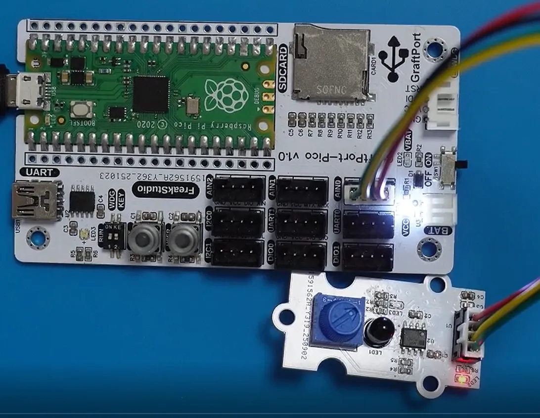
The module connections are shown in the following table:
Development Board Pins | Module Pins | Description |
Pin 26 |
| Analog Output of Flame Sensor |
Pin 19 |
| Digital output of the flame sensor analog signal after passing through the comparator |
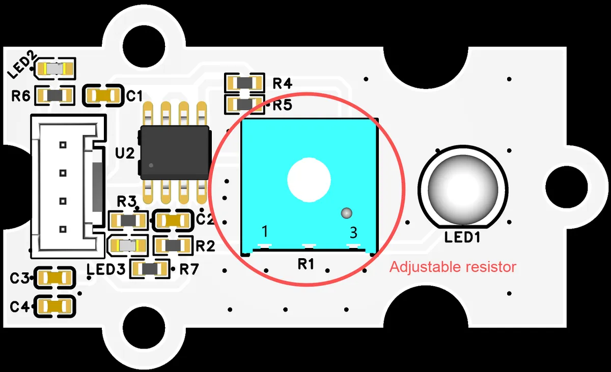
Based on the PT334 flame sensor working principle (the sensor realizes induction by detecting the specific infrared radiation released by the flame), the core function of the adjustable resistor on the module (i.e. R1 in the figure win the bidding) is to set the detection threshold : the smaller the resistance value (usually adjusted clockwise), the lower the trigger threshold of the sensor and the more sensitive it is to the flame; the larger the resistance value (adjusted counterclockwise), the stricter the trigger conditions and the stronger the ability to resist environmental stray light interference.
First, turn this adjustable resistor clockwise to gradually lower the trigger threshold until the sensor's trigger indicator LED2 lights up — at this point, the ambient infrared signal (or the target flame signal) just reaches the sensor's trigger critical state; to avoid false triggers caused by ambient stray infrared light, then gently turn the adjustable resistor counterclockwise for a slight adjustment, and wait until LED2 goes out, the sensor's threshold will accurately fall within a reasonable range that "approaches the flame trigger condition while being able to avoid false triggers".
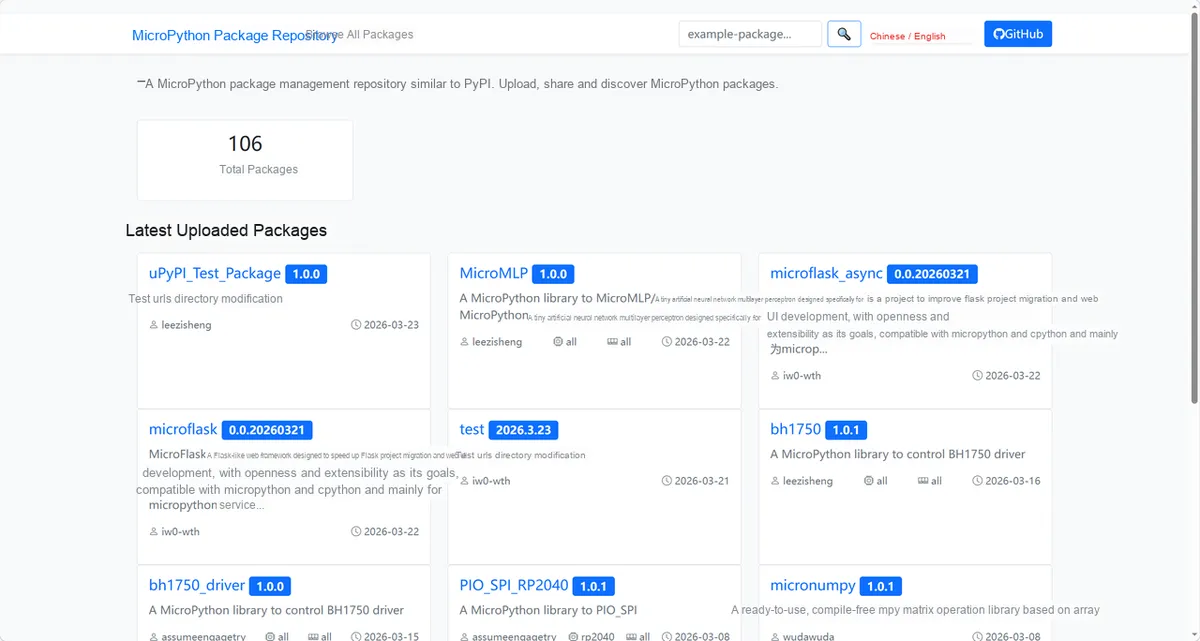
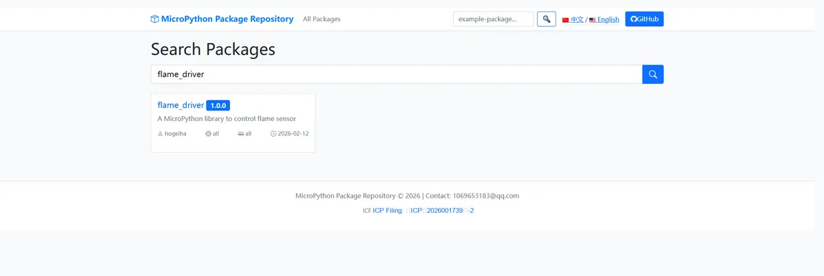
Here, we need to search for the relevant driver packages on uPyPI: https://upypi.net/zh/
Enter flame_driver to search, and the following will be displayed:
Click to copy the local installation command:
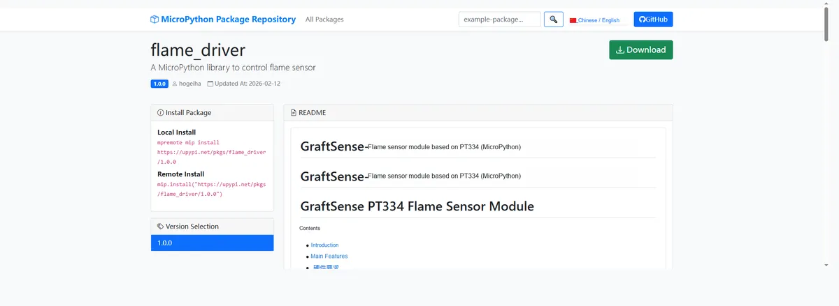
Here, we can use the mip tool to import module driver library code. The following are the usage commands for the mpremote tool:
mpremote mip install github:FreakStudioCN/GraftSense-Drivers-MicroPython/sensors/flame_driverImport the flame sensor module based on PT334 - MicroPython driver code, then copy the following main.py code into our project:
# MicroPython v1.23.0
# -*- coding: utf-8 -*-
# @Time    : 2025/8/23 5:55 PM
# @Author  : 缪贵成
# @File    : main.py
# @Description : Flame sensor driver test file

# ======================================== Import Modules =========================================

import time
from machine import Pin
from flame_sensor import FlameSensor

# ======================================== Global Variables =============================================

# ======================================== Functions =============================================

def flame_detected_callback() -> None:
    """
    Flame detection callback function. Called by micropython.schedule when the digital pin DO triggers.

    Notes:
        The callback runs in the main thread, so it is safe to print or control the LED.

    ==========================================

    Callback function triggered on flame detection.
    Called by micropython.schedule when digital pin DO triggers.

    Notes:
        Safe to perform printing or LED control in main thread.
    """
    print("Flame detected!")

# ======================================== Custom Classes =============================================

# ======================================== Initialization configuration ===========================================

print("FreakStudio:Testing Flame Sensor")
time.sleep(3)

# Initialize the flame sensor object, assuming the analog output pin is 26 and the digital output pin is 19
flame_sensor = FlameSensor(analog_pin=26, digital_pin=19, callback=flame_detected_callback)
# Enable the digital pin interrupt
flame_sensor.enable()

# ======================================== Main Program ==============================================

print("=== Flame Sensor Initialized. Monitoring AO voltage... ===")

try:
    while True:
        # Get the AO analog value and convert it to voltage
        voltage = flame_sensor.get_voltage()
        print("AO Voltage: {:.2f} V".format(voltage))
        time.sleep(1)
except KeyboardInterrupt:
    print("=== Test Stopped by User ===")
    flame_sensor.disable()
Burn the code, open the terminal, and use the mpremote tool to connect to the main controller. The output is as follows:
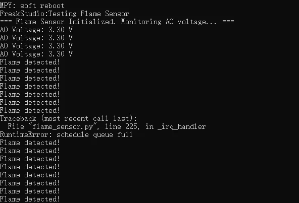
As you can see, when the flame of a lighter triggers our sensor module, the trigger callback will print on the terminal Flame detected!
IV. Drivers
flame_driver.zip 12 KB
5. BOM & Recommended Alternative Parts
None.
VI. Revision History
Document Version | Date of Modification | Modifier | Modified Content |
v1.0 | 2025-08-31 | Hou Junhan Ling Gaoxing | Complete the initial design and the preparation of hardware documents |
v1.1 | 2025-10-09 | Li Zisheng | Added PCB routing precautions for Version 2.8 Revised Section 3, Instructions for Circuit Source Project and Module Usage, and added a secondary heading: 3.1 Circuit Source Engineering, 3.2 Module Usage Instructions, 3.3 Application Experiments The BOM sheet has not been finally checked, the driver has not been re-verified, and the 3.3 application experiment Not yet specified. |
v1.2 | 2025-12-29 | Li Zisheng | Added application experiments and production files |
v1.3 | 2025-12-31 | Xin Ruili | Create an open version of the document based on the internal document version v1.2. |
v1.4 | 2026-03-29 | Xin Ruili | Modified the application experiment section |
VII. Relevant Materials
7.1 Chip Datasheet
PT334 Datasheet.pdf 497 KB
C351428_Comparator_LM393_Datasheet_WJ131819.PDF 1.0 MB
7.2 Unique Icons for PCB Silkscreen