Contents
- I. Module Introduction
- II. Introduction to Main Chips
- 2.1 Chip Overview
- 2.2 Pin Definition
- 2.3 Functional Block Diagram
- 2.4 Performance Parameters
- 2.5 Reference Circuit
- 2.6 Chip Configuration
- 2.7 Communication Interfaces and Related Protocols
- 2.8 PCB Routing Precautions
- III. Circuit Engineering
- 3.1 Circuit Source Engineering
- 3.2 Module Usage Instructions
- 3.3 Application Experiment
- IV. Drivers
- 5. BOM & Recommended Alternative Parts
- VI. Revision History
- VII. Relevant Materials
- 7.1 Chip Datasheet
- 7.2 Unique Icons for PCB Silk Screen
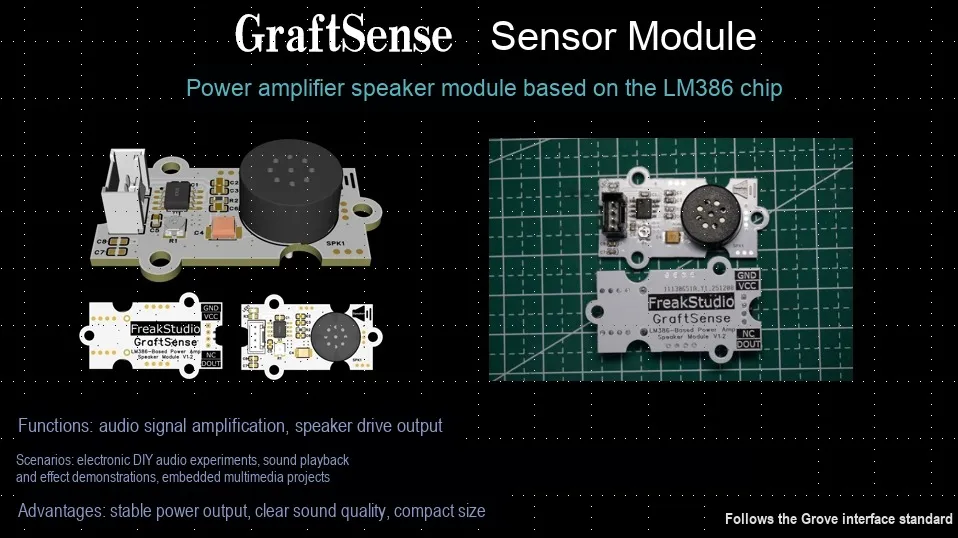
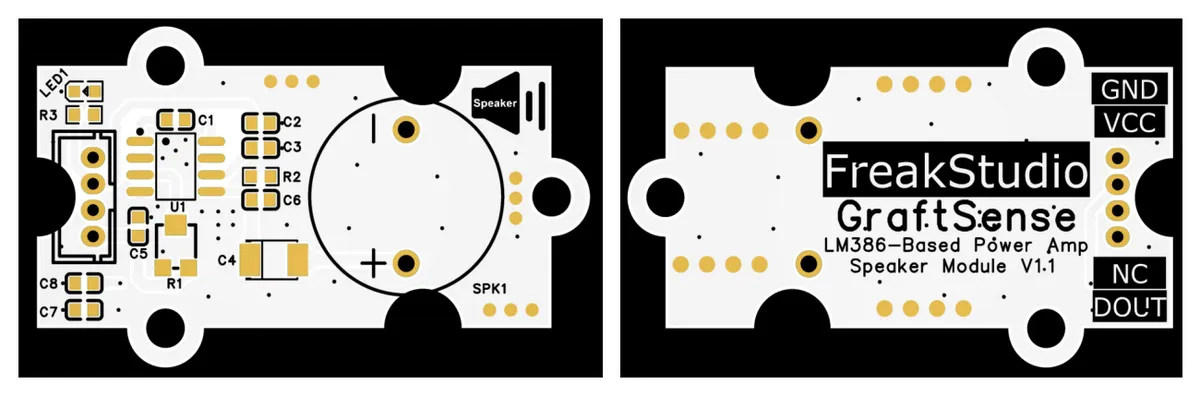
I. Module Introduction
Power Amplifier Speaker Module Based on LM386 Chip, with the LM386 audio power amplifier chip as the core, features a power supply input voltage of + 5V and an optional gain load impedance ranging from 4 to 32Ω. The module has a fixed gain of 200 (46dB); the 20kΩ potentiometer R1 at the signal input terminal can adjust the output volume.The module is equipped with MCU interfaces, power filtering components and power indicator lights. After the input signal is amplified, it can be played out loud through a speaker, which is suitable for scenarios such as small audio playback and voice prompts, and provides a concise and efficient power amplification solution for the audio output of embedded systems.
II. Introduction to Main Chips
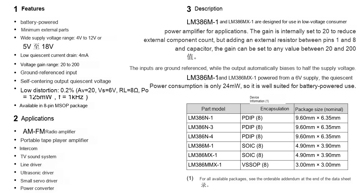
LM386 is a low-voltage audio power amplifier chip featuring a wide supply voltage range (4V~12V, typically 9V), a quiescent current of only 4mA and extremely low power consumption. It offers adjustable gain (20 times by default, expandable up to 200 times with external resistors and capacitors), a maximum output power of 0.5W (with an 8Ω load), supports single-supply operation, requires only a small number of components for a simple peripheral circuit, comes in compact 8-pin DIP or SOIC packages, boasts small form factor, low cost and strong anti-interference capability, and is widely used in low-power audio amplification scenarios such as radios, walkie-talkies, compact speakers and toys.
2.1 Chip Overview
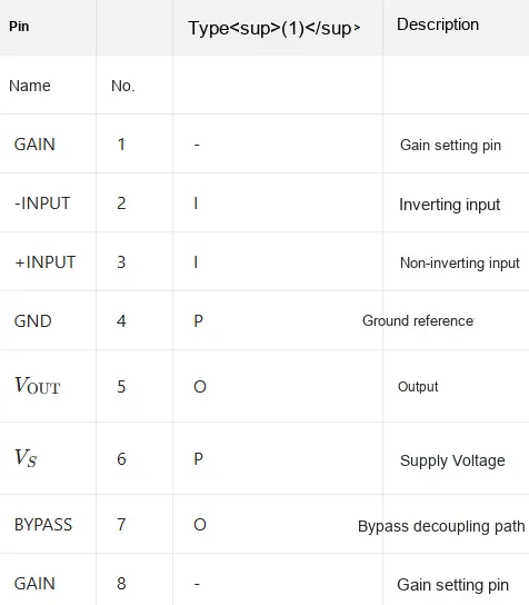
2.2 Pin Definition
2.3 Functional Block Diagram
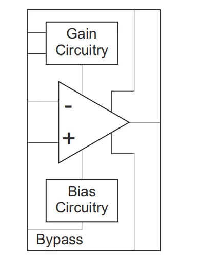
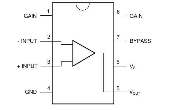
LM386 The functional block diagram is described as follows:
- Signal Amplification and Arithmetic Module
- Operational amplifier (including inverting input marked with "-", non-inverting input marked with "+", and output terminal): performs operational amplification on the input analog signals and serves as the core unit for signal processing.
- Gain Circuitry: It adjusts the gain of the operational amplifier, controls the signal amplification factor, and adapts to the requirements of input signals with different amplitudes.
- Bias and Power Supply Module
- Bias Circuitry: Provides appropriate bias voltage for the operational amplifier to ensure that it operates in the linear region and guarantees stable amplification performance.
- Bypass (Bypass Circuit): It is commonly used to connect an external bypass capacitor to filter power supply noise and stabilize circuit power supply.
Typical application scenarios of analog signal amplification:
- Signal Input: An external analog signal is connected to the "+" or "-" input terminal of the operational amplifier → the Gain Circuitry sets the amplification factor → the operational amplifier amplifies the signal.
- Bias and Power Supply: The Bias Circuitry provides a bias voltage for the operational amplifier → the external Bypass capacitor filters out power supply noise → the amplified signal is output from the output terminal for use by subsequent circuits.
2.4 Performance Parameters
- Power Supply and Power Consumption :
- Supply Voltage For LM386N-1/-3 and similar models, the supply voltage ranges from 4V to 12V; for LM386N-4, it ranges from 5V to 18V;
- Package power dissipation: maximum 1.25W for LM386N, maximum 0.73W for LM386M, maximum 0.595W for LM386MM-1;
- Quiescent Current Typ. 4~8 mA (VS = 6 V, VIN = 0).
- Input/Output:
- Input Voltage - 0.4~0.4V;
- Output power under different conditions reaches a maximum of 325mW, 700mW and 1000mW respectively;
- Voltage Gain Typically 26dB (without external capacitor), 46dB (with 10μF external capacitor).
- Performance Indicators:
- Bandwidth 300kHz;
- Total Harmonic Distortion 0.2%;
- Power Supply Rejection Ratio 50dB;
- Input resistance 50kΩ;
- Input bias current 250nA.
- Environmental Storage: Storage temperature: -65~150℃.
2.5 Reference Circuit
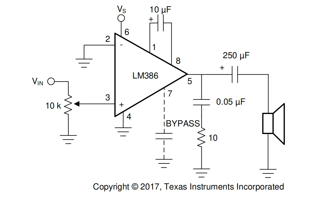
This is a circuit based on the LM386 audio power amplifier: the input signal Vin is adjusted via a 10k potentiometer, a 10μF capacitor between pin 1 and pin 8 is used to configure high gain, the output terminal drives the speaker through a 250μF DC blocking capacitor, and a 0.05μF capacitor in series with a 10Ω resistor forms an anti-oscillation network to realize the amplification and playback of audio signals.
2.6 Chip Configuration
None.
2.7 Communication Interfaces and Related Protocols
None.
2.8 PCB Routing Precautions
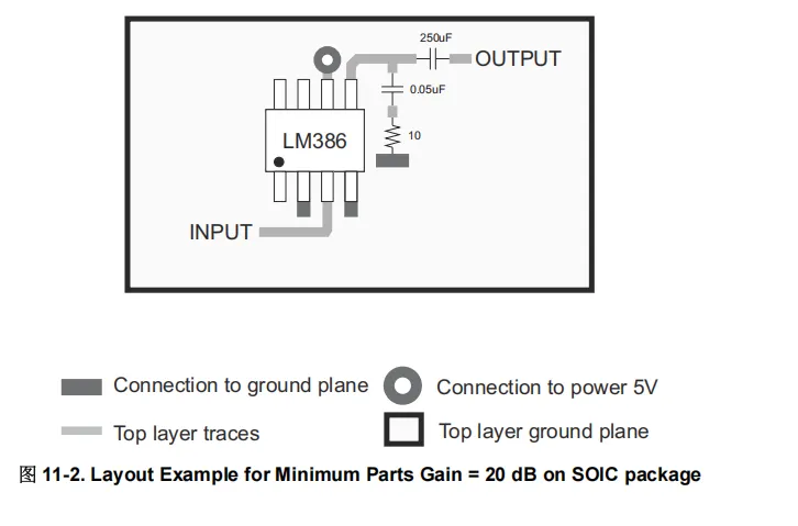
Place all required components as close to the device as possible. Keep the output traces connected to the speaker short. Route analog traces away from digital signal traces and avoid crossing them.
Layout Example:
III. Circuit Engineering
3.1 Circuit Source Engineering
To obtain the source code of the circuit, please follow the official account [Freak Embedded]
3.2 Module Usage Instructions
SCH_Schematic1_Power Amplifier Speaker Module Based on LM386 Chip-V1.1.0_2025-11-17.pdf 2.1 MB
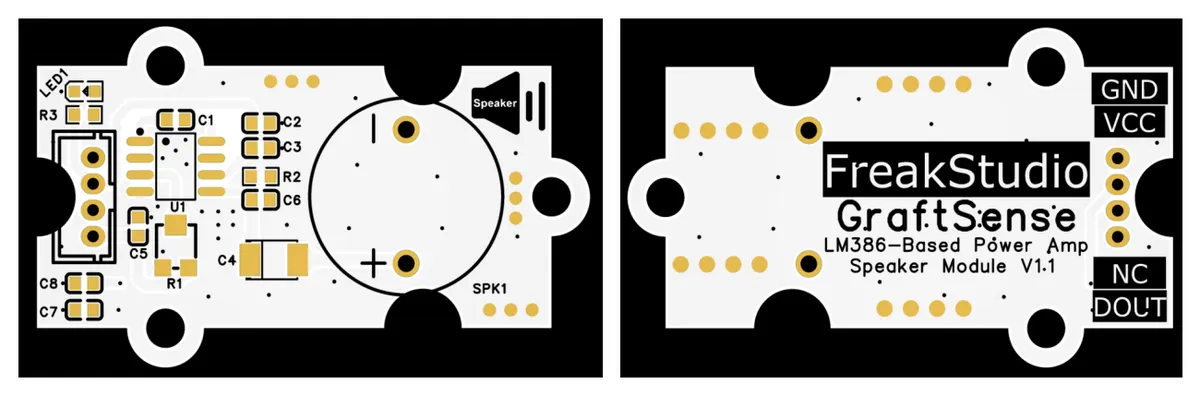
This module uses a digital input DOUT: this DOUT interface needs to be connected to the MCU PWM output channel, to receive the audio MCU outputs PWM signal; the frequency of the audio PWM signal is recommended to be set to 20kHz or higher, which can effectively avoid high-frequency noise interference audible to the human ear;After being processed by the internal circuit of the module, this input signal is sent to the LM386 audio power amplifier chip for power amplification with a fixed gain of 200 (46dB). Meanwhile, the output volume can be adjusted via the 20kΩ potentiometer R1, and finally the sound is played out through a speaker with a load impedance of 4-32Ω. This solution is suitable for scenarios such as small audio playback and embedded system voice prompts, and provides a convenient digital input adaptation scheme for the power amplification and output of audio signals.
3.3 Application Experiment
Here, we use the GraftPort-RP2040 development board for testing, and connect the power amplifier speaker module based on the LM386 chip to communicate with the main controller via the DIO interface.
Here, we first use the HY2.0-4P cable to connect the module to the GraftPort-RP2040 development board's DIO0 interface:
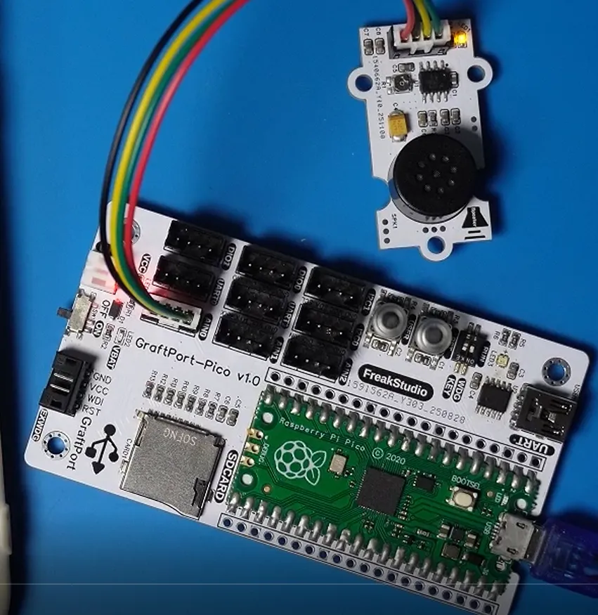
The module connections are shown in the following table:
Development Board Pins | Module Pins | Description |
Pin 6 |
| PWM output pins on the MCU |
Pin 7 |
| - |
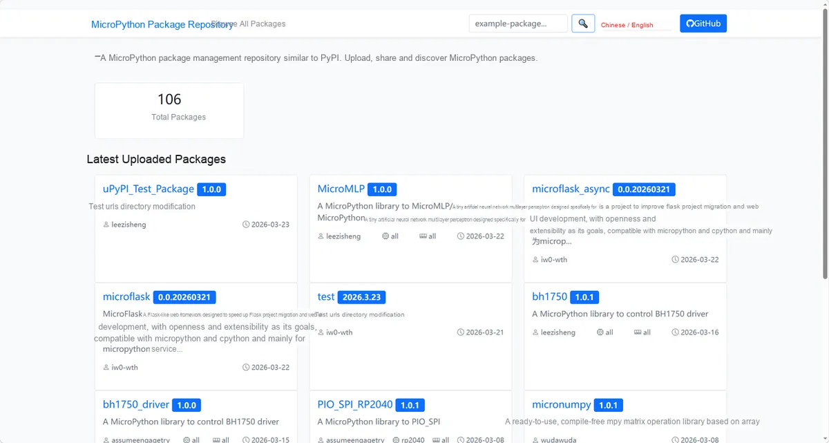
Here, we need to search for relevant driver packages on uPyPI: https://upypi.net/zh/
Enter lm386_speaker_driver to search, and the following will be displayed:
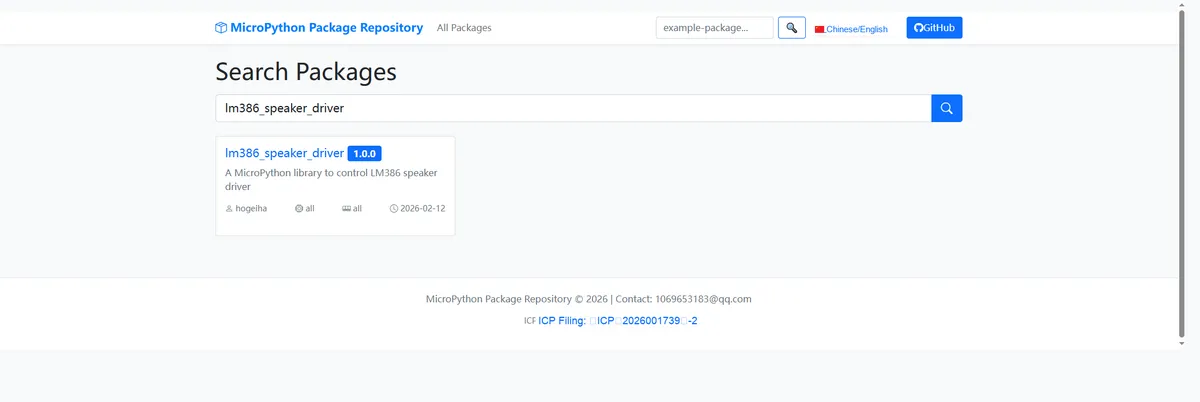
Click to copy the local installation command:
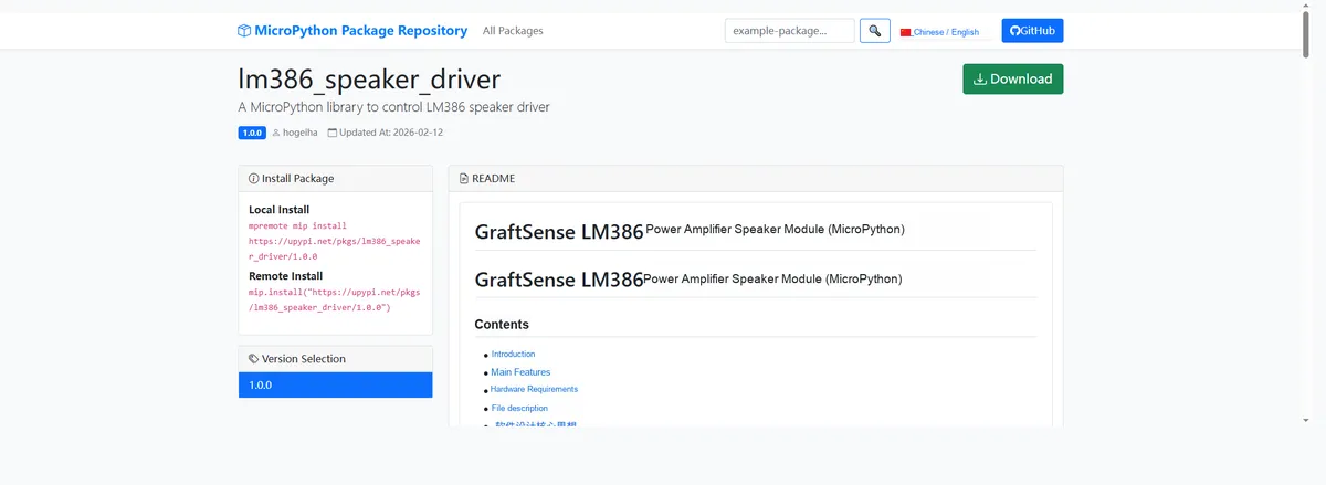
Here, we can use the mip tool to import module driver library code. Below are the usage commands for the mpremote tool:
mpremote mip install github:FreakStudioCN/GraftSense-Drivers-MicroPython/misc/lm386_speaker_driverImport the LM386 Power Amplifier Speaker - MicroPython Driver Code, then copy the following main.py code into our project:
# Python env   : MicroPython v1.23.0
# -*- coding: utf-8 -*-
# @Time    : 2025/9/9 3:31 PM
# @Author  : 缪贵成
# @File    : main.py
# @Description : Driver test file for the LM386-based power amplifier speaker module

# ======================================== Import Modules =========================================

from lm386_speaker import LMSpeaker
import time

# ======================================== Global Variables ============================================

# ======================================== Functions ============================================

# ======================================== Custom Classes ============================================

# ======================================== Initialization ==========================================

time.sleep(3)
print("FreakStudio:Testing the driving of the LM386-based power amplifier speaker module.")
# Initialize the speaker, assuming PWM pin = 26
speaker = LMSpeaker(pin=26, freq=1000)

# ========================================  Main Program  ============================================

print("Play the single tone 440Hz (A4, lasting 3 second) ")
speaker.play_tone(440, 1.0)   # Play note A4
time.sleep(3)

print("Play the note sequence (simple melody).")
melody = [
    (440, 0.5),  # A4
    (494, 0.5),  # B4
    (523, 0.5),  # C5
    (587, 0.5),  # D5
    (659, 0.5),  # E5
    (698, 0.5),  # F5
    (784, 1.0),  # G5
]
speaker.play_sequence(melody)
time.sleep(1)

print("Test volume adjustment.")
for vol in [20, 40, 60, 80, 100]:
    print("Volume:", vol, "%")
    speaker.set_volume(vol)
    # C5
    speaker.play_tone(523, 0.5)
    time.sleep(0.2)

print("Mute...")
speaker.stop()
To flash the code, open a terminal and use the mpremote tool to connect to the main controller; the output is as follows:
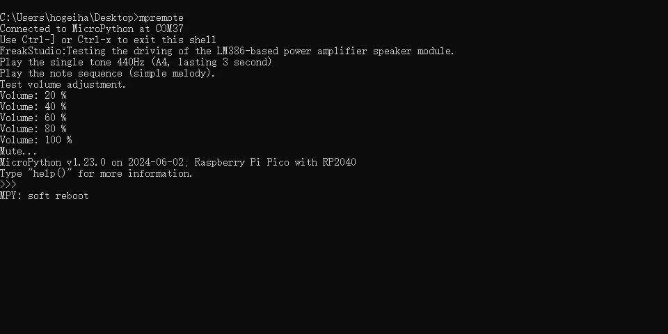
As you can see, our module emits sounds of different pitches:
IV. Drivers
lm386_speaker_driver.zip 11 KB
5. BOM & Recommended Alternative Parts
None.
VI. Revision History
Document Version | Date of Revision | Modifier | Revised Content |
v1.0 | 2025-11-17 | Zero Kōkō | Initialize the document |
v1.1 | 2025-12-29 | Li Zisheng | Added application experiments and production files |
v1.2 | 2025-12-31 | Xin Ruili | Create an open version of the document based on the internal document version v1.1. |
v1.3 | 2026-03-29 | Xin Ruili | Modified the application experiment section |
VII. Relevant Materials
7.1 Chip Datasheet
lm386.pdf 1.6 MB
7.2 Unique Icons for PCB Silk Screen