Contents
- I. Module Introduction
- II. Introduction to Main Chips
- 2.1 Chip Overview
- 2.2 Pin Definition
- 2.3 Functional Block Diagram
- 2.4 Performance Parameters
- 2.5 Reference Circuit
- 2.6 Chip Configuration
- 2.7 Communication Interfaces and Related Protocols
- 2.8 PCB Routing Precautions
- III. Instructions for Circuit Engineering and Module Usage
- 3.1 Circuit Source Engineering
- 3.2 Module Usage Instructions
- 3.3 Application Experiment
- IV. Drivers
- 5. BOM & Recommended Alternative Parts
- VI. Revision History
- VII. Relevant Materials
- 7.1 Chip Datasheet
- 7.2 Unique Icons for PCB Silk Screen
I. Module Introduction
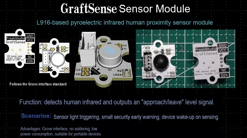
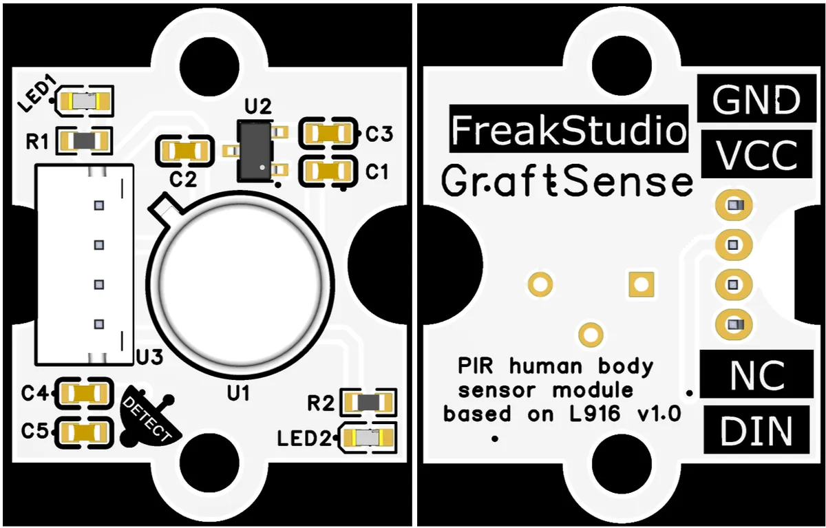
The infrared pyroelectric human proximity sensor module based on L916 is an L916 -based infrared pyroelectric human proximity sensor module. With the L916 pyroelectric probe as the core, it integrates a 5V to 3.3V power supply circuit, a power indicator, filter capacitors and wiring terminals, and outputs human proximity detection signals via the DIN interface. It can accurately detect the presence of the human body and is suitable for scenarios such as smart sensing devices and security systems.
II. Introduction to Main Chips
2.1 Chip Overview
2.2 Pin Definition
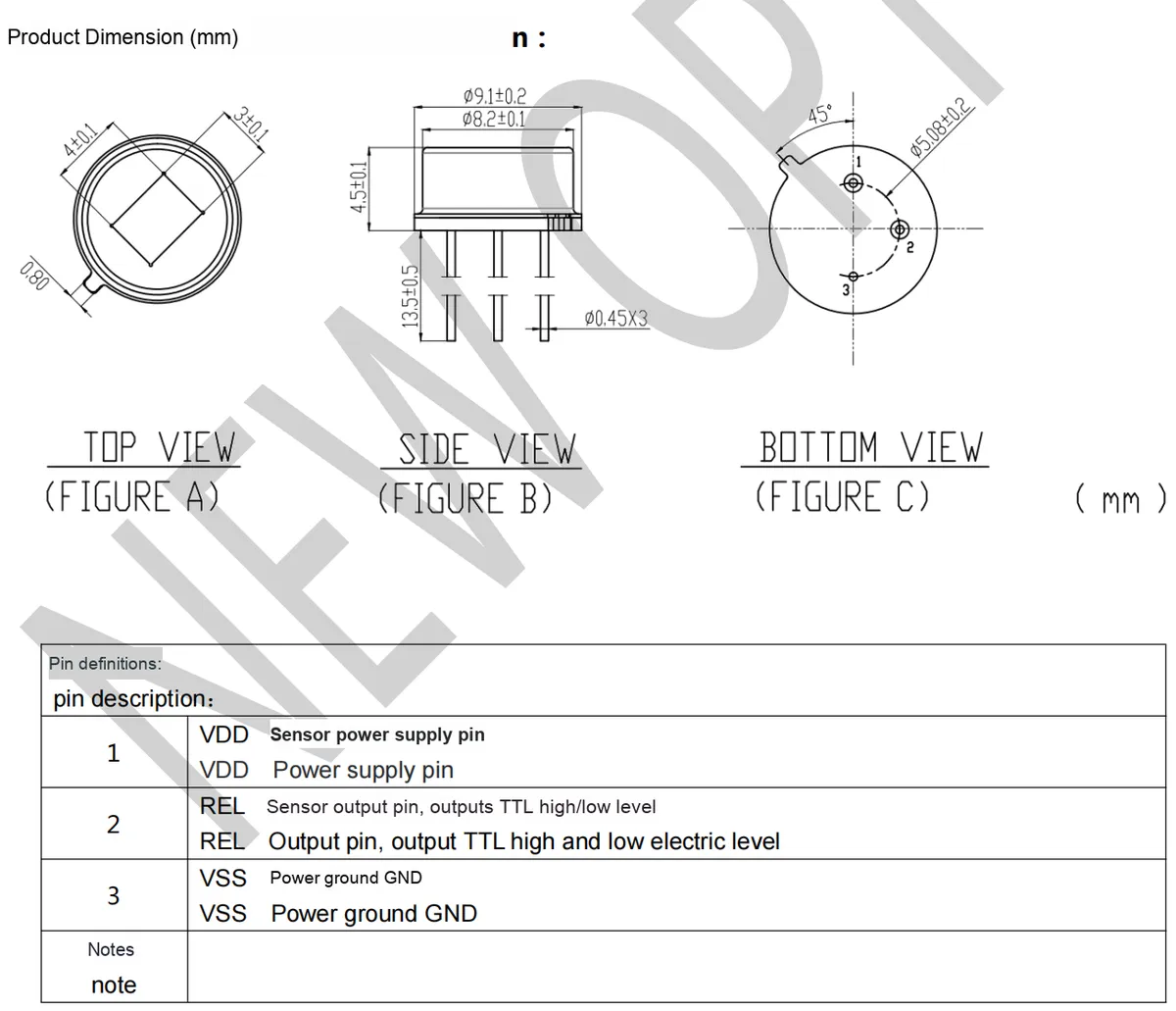
2.3 Functional Block Diagram
The following functional block diagram illustrates the internal signal processing flow of the L916-based infrared pyroelectric sensor:
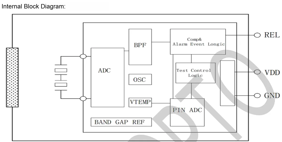
The functions of each module are as follows:
- Left sensor probe: Receives the infrared signal emitted by the human body and converts thermal energy into an electrical signal.
ADC(Analog-to-Digital Converter): Converts the analog electrical signal output by the sensor into a digital signal to facilitate subsequent processing.BPF(Band-Pass Filter): filters out signals that match the frequency of human movement (typically 0.3~3Hz), while rejecting environmental noise and interference from irrelevant frequencies.OSC(Oscillator): Provides clock signals for the internal circuits of the chip to ensure timing synchronization of all modules.VTEMP(Temperature Detection): Monitors the chip or ambient temperature for temperature compensation to improve detection accuracy.BAND GAP REF(Bandgap Reference): Provides a stable voltage reference to ensure the accuracy of modules such as ADCs and comparators.Comp&Alarm Event Logic(Comparator and Alarm Event Logic): Compare the processed signal with the threshold to determine whether a human body approaching event is triggered, and finally output the detection result through theRELpin.Test Control Logic(test control logic) andPIN ADC: used for chip testing and debugging to ensure mass production and functional verification.- Power Interface (
VDD,GND): Supplies power and grounding for the chip.
2.4 Performance Parameters
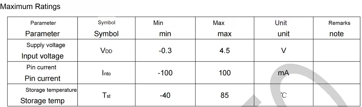
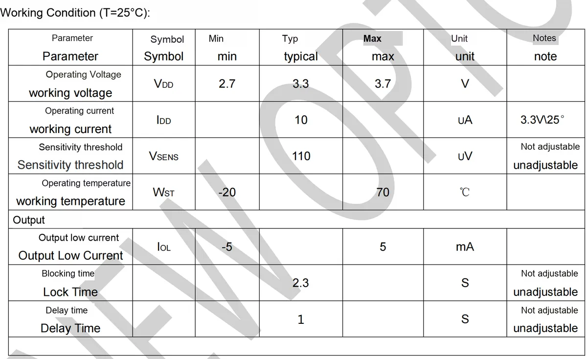
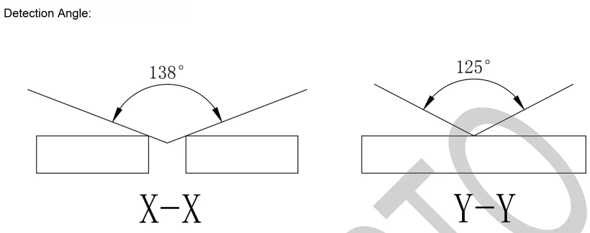
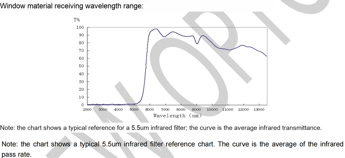
This graph shows the transmittance curve of a typical 5.5μm infrared filter, with the horizontal axis representing wavelength (nm) and the vertical axis representing transmittance (T %). As the curve demonstrates, this filter in the wavelength range from 5000nm (5μm) to 13000nm (13μm) features a high infrared transmittance, which can effectively screen out the infrared radiation of the human body (with a peak at approximately 10μm). It provides optical support for the accurate detection of the human body by infrared pyroelectric sensors, ensuring that only infrared signals in the target wavelength band can pass through, thus improving the accuracy of human proximity detection.
2.5 Reference Circuit
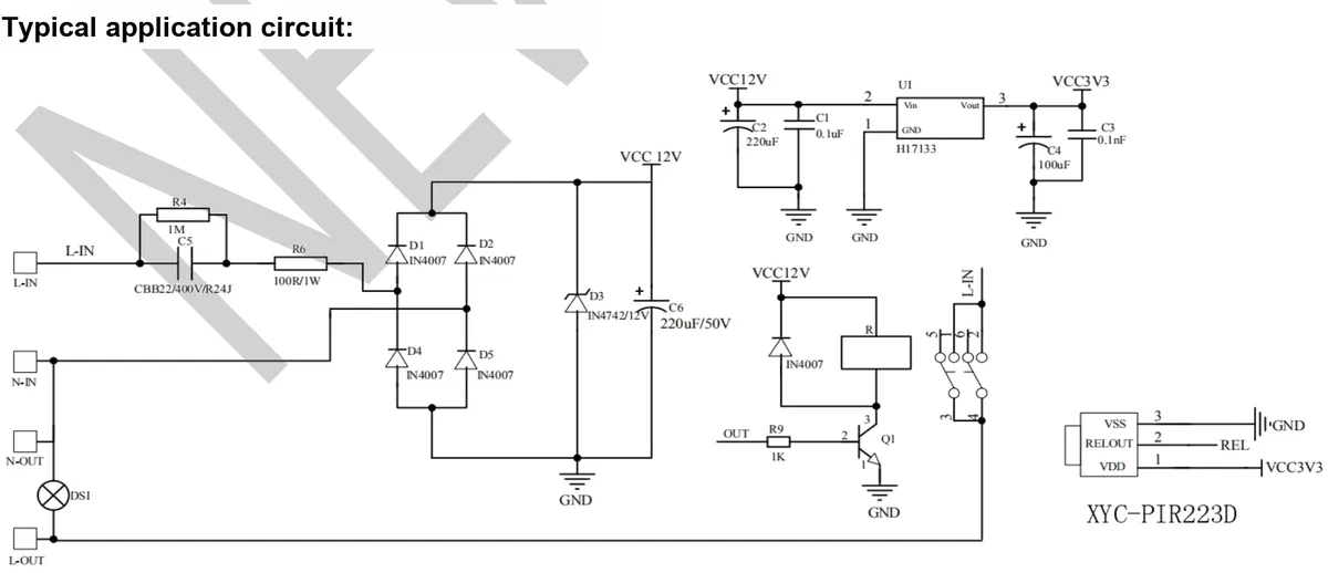
This typical application circuit is a human body detection system based on XYC-PIR223D infrared pyroelectric sensor, which integrates power conversion (HI7133 converts 12V to 3.3V to power the sensor), signal filtering and protection (diode rectifier bridge, voltage regulator tube, RC filtering), human body detection (XYC-PIR223D module) and control output (triode, relay drive) and other links, realizing the complete functions from power supply, signal conditioning to human induction trigger execution, which is suitable for intelligent control scenarios of infrared human body induction (such as automatic lighting, security trigger, etc.).
2.6 Chip Configuration
None.
2.7 Communication Interfaces and Related Protocols
None.
2.8 PCB Routing Precautions
None.
III. Instructions for Circuit Engineering and Module Usage
3.1 Circuit Source Engineering
To obtain the source code of the circuit, please follow the official account [Freak Embedded]
3.2 Module Usage Instructions
The schematic diagram of this module is shown below:
SCH_L916-Based Infrared Pyroelectric Human Proximity Sensor Module_v1.0_2025-10-23.pdf 2.3 MB
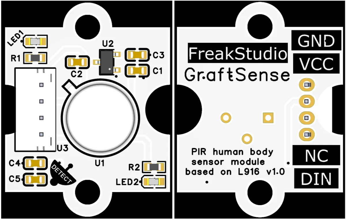
This module provides a signal output interface DIN: this interface is used to output the digital signal of human proximity detection.
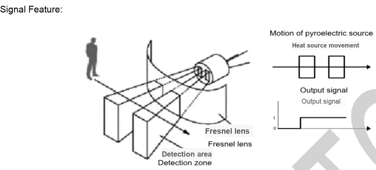
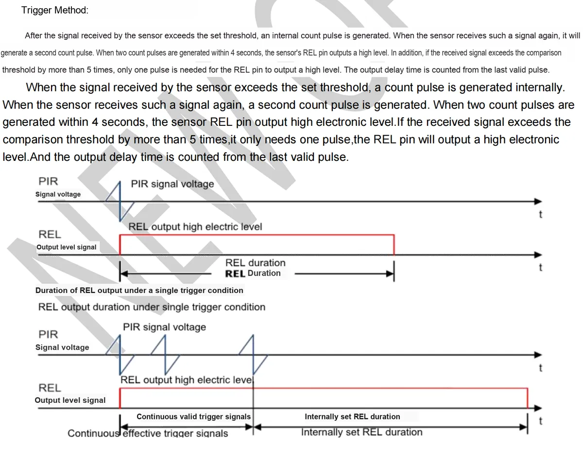
Its working principle is as follows: the infrared thermal radiation of the human body is focused by the Fresnel lens and then received by the L916 pyroelectric probe and converted into an electrical signal; internally, the analog signal is first digitized by the ADC, and then the characteristic frequency signal of human movement is filtered out by a band-pass filter (BPF), and the judgment is made in combination with the comparator and the alarm event logic. When the detection signal exceeds the set threshold, if two counting pulses are generated within 4 seconds, or a single pulse exceeds 5 times the threshold, the DIN interface will output a high level;This signal accurately reflects the movement trigger state of a human body within the detection area, provides external devices (such as a microcontroller) with digital feedback on human proximity, and realizes the complete human body induction logic covering infrared signal acquisition, internal processing and signal output.
3.3 Application Experiment
Here, we use the GraftPort-RP2040 development board for testing, and connect the L916-based pyroelectric infrared human proximity sensor module to communicate with the main controller via the DIO interface.
Here, we first use the HY2.0-4P cable to connect the module to the GraftPort-RP2040 development board's DIO0 interface:
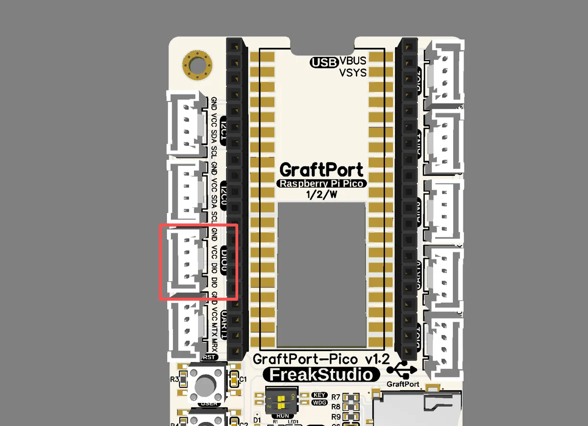
The module connections are shown in the following table:
Development Board Pins | Module Pins | Description |
Pin 6 |
| Signal input pins of the modules on the MCU |
Pin 7 |
| - |
Here, we need to search for relevant driver packages on uPyPI: https://upypi.net/zh/

Enter pir_driver to search, and the following will be displayed:

Click to copy the local installation command:
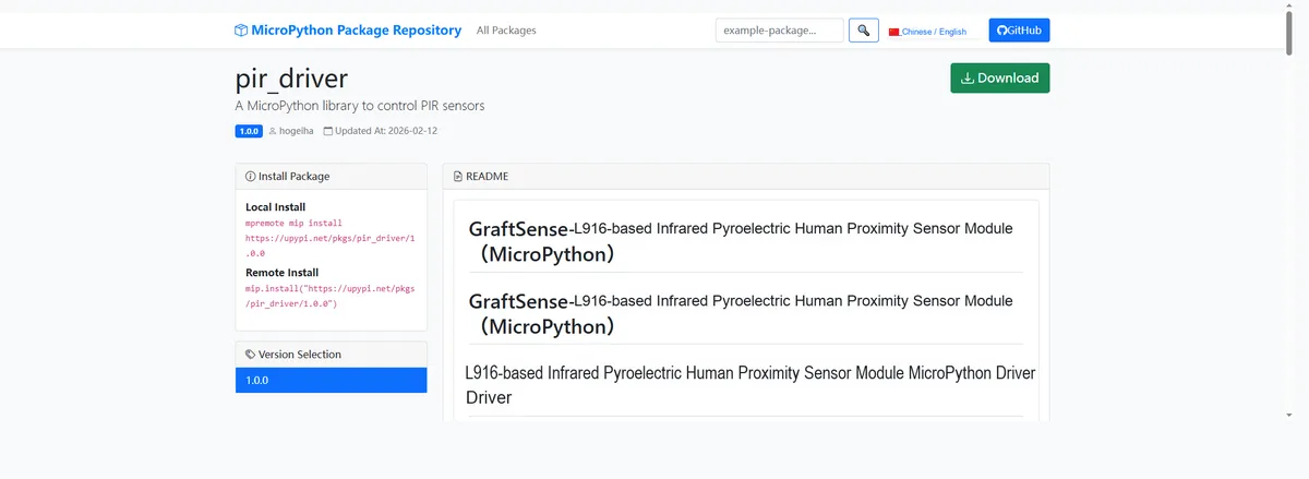
Here, we can use the mip tool to import module driver library code. Below are the usage commands for the mpremote tool:
mpremote mip install github:FreakStudioCN/GraftSense-Drivers-MicroPython/sensors/pir_driverImport the PIR Motion Sensor - MicroPython Driver Code, then copy the following main.py code into our project:
# Python env   : MicroPython v1.23.0
# -*- coding: utf-8 -*-
# @Time    : 2025/8/29 6:47 PM
# @Author  : 缪贵成
# @File    : main1.py
# @Description : Test file for the infrared human pyroelectric sensor driver

# ======================================== Import related modules =========================================\

from pir_sensor import PIRSensor
import time

# ======================================== Global Variables ============================================

# ======================================== Functions ============================================

def motion_callback():
    """
    Callback function

    ==========================================

    callback function
    """
    print("Motion detected!")

# ======================================== Custom Classes ============================================

# ======================================== Initialization configuration ===========================================

# Power-on delay of 3 s
time.sleep(3)
print("FreakStudio : Infrared human body pyro-release sensor test")

# Create the infrared human pyroelectric sensor object
pir = PIRSensor(pin=6, callback=motion_callback)

# ========================================  Main Program  ============================================

# Prompt the user to come closer
print("Waiting for motion...")
# Block and wait, no timeout
detected = pir.wait_for_motion(timeout=20)

if detected:
    # Block and wait for motion to be detected
    print("Motion detected via blocking wait!")
else:
    print("Timeout, no motion detected.")
To flash the code, open a terminal and use the mpremote tool to connect to the main controller; the output is as follows:
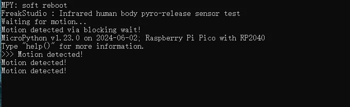
It can be seen that when a human body is detected, the sensor outputs a corresponding level signal, which triggers the interrupt callback function. Meanwhile, the trigger indicator status light on the module LED2 lights up:
IV. Drivers
pir_driver.zip 9 KB
5. BOM & Recommended Alternative Parts
None.
VI. Revision History
Document Version | Date of Revision | Modifier | Revised Content |
v1.0 | 2025-8-31 | Hou Junhan Zero Kōkō | Initialize the document |
v1.1 | 2025-10-23 | Li Zisheng | Added PCB layout precautions for Version 2.8 Revised Section 3, Instructions for Circuit Source Project and Module Usage, and added a secondary heading: 3.1 Circuit Source Engineering, 3.2 Module Usage Instructions, 3.3 Application Experiments The BOM sheet has not been finally checked, the driver has not been re-verified, and the 3.3 application experiment Not yet specified. |
v1.2 | 2025-12-29 | Li Zisheng | Added application experiments and production files |
v1.3 | 2025-12-31 | Xin Ruili | Create an open-version document based on the internal document version v1.2. |
v1.4 | 2026-03-29 | Xin Ruili | Modified the application experiment section |
VII. Relevant Materials
7.1 Chip Datasheet
C2887901_Human Body Sensor_PIR223D-S0_Datasheet_WJ236843.PDF 910 KB
7.2 Unique Icons for PCB Silk Screen