Contents
- I. Module Introduction
- II. Introduction to Main Chips
- 2.1 Chip Overview
- 2.2 Pin Definition
- 2.3 Functional Block Diagram
- 2.4 Performance Parameters
- 2.5 Reference Circuit
- 2.6 Chip Configuration
- 2.7 Communication Interfaces and Related Protocols
- 2.8 PCB Routing Precautions
- III. Circuit Engineering
- 3.1 Circuit Source Engineering
- 3.2 Module Usage Instructions
- 3.3 Application Experiment
- IV. Drivers
- 5. BOM & Recommended Alternative Parts
- VI. Revision History
- 7. Relevant Materials
- 7.1 Chip Datasheet
- 7.2 Unique Icons for PCB Silk Screen
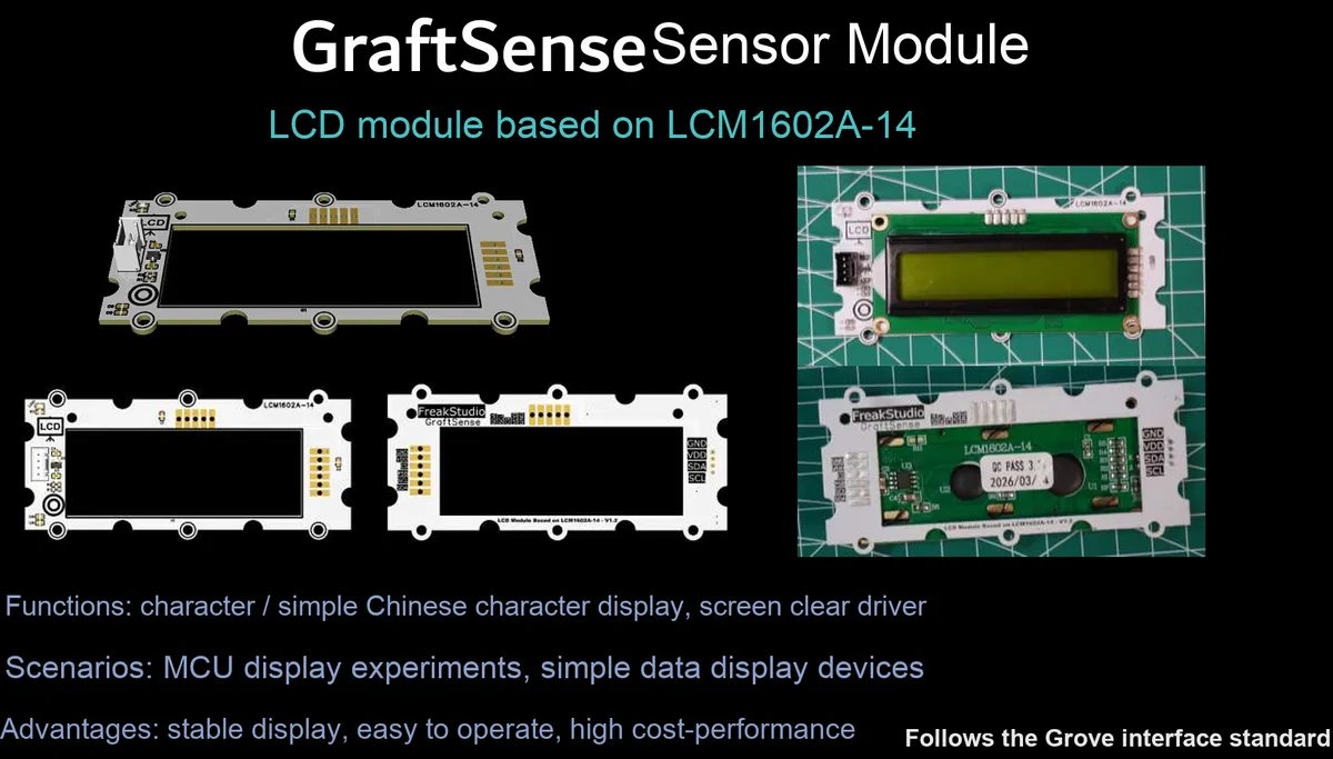
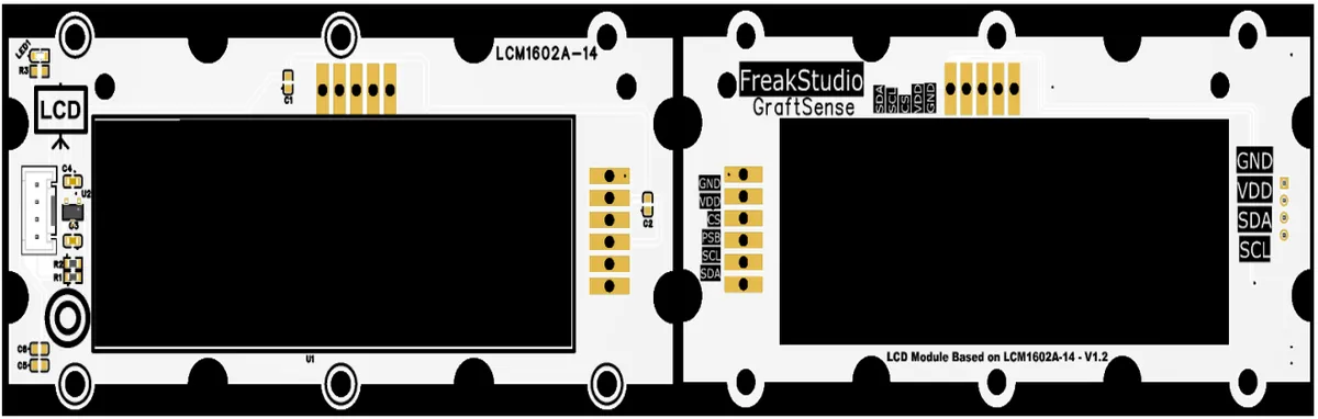
I. Module Introduction
Based on the liquid crystal display module of LCM1602A-14, this product adopts the LCM1602A-14 display scheme, supports serial I²C interface communication, features a display specification of 2 lines × 16 characters (5×8 dot matrix), and has a built-in 5V to 3.3V DC-DC power supply circuit, power filtering and indicator circuit, with a logic power supply of 3.3V. It can stably realize character and cursor display, and is suitable for scenarios requiring basic text display such as embedded development, maker projects and industrial instruments.
II. Introduction to Main Chips
LCM1602A-14 is a dot-matrix LCD with a 2-line × 16-character layout, supporting the serial I²C interface, powered by 3.3V logic supply, capable of displaying characters and cursors, and suitable for embedded text output scenarios.
2.1 Chip Overview
None.
2.2 Pin Definition
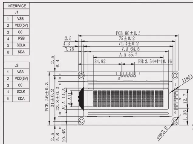
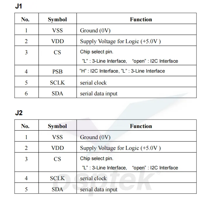
LCM1602A-14 is a dot-matrix LCD with 2 rows × 16 characters, supporting I²C/3-wire serial two interfaces (switchable via the pin levels of CS / PSB), and comes with dual interface sockets (J1 / J2). It operates on a 5V logic supply, supports character and cursor display, and is suitable for embedded text output applications.
2.3 Functional Block Diagram
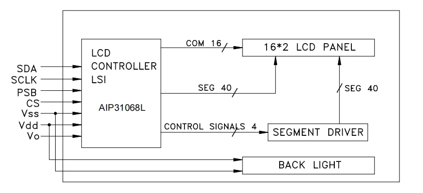
LCM1602A-14 Core Principle of the LCD Module: The module adopts AIP31068L as its LCD control and driving core, receives commands and data through serial interfaces such as SDA and SCLK, internally generates driving signals for 16 common terminals (COM) and 40 segment terminals (SEG), and cooperates with the segment driving circuit to drive the 16×2 character-type LCD panel to display content. Meanwhile, the module integrates a backlight circuit, which is directly powered by the power supply to realize backlighting, thus completing the full function from serial communication to character display as a whole.
2.4 Performance Parameters
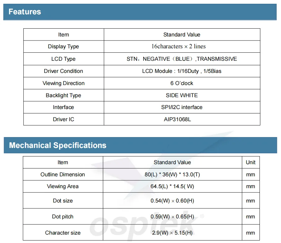
LCM1602A-14 is a 2-line × 16-character STN blue-mode negative-transmissive liquid crystal display module, which adopts the AIP31068L driver IC, supports SPI / I²C serial interfaces, features side-mounted white LED backlight, and offers a 6 o'clock viewing angle;The driving mode features 1/16 duty ratio and 1/5 bias; it has external dimensions of 80mm × 36mm × 13mm, a viewing area of 64.5mm × 14.5mm, dot size of 0.54mm × 0.60mm, and character size of 2.9mm × 5.15mm, making it suitable for scenarios requiring basic text display such as embedded development, industrial instruments, and maker projects.
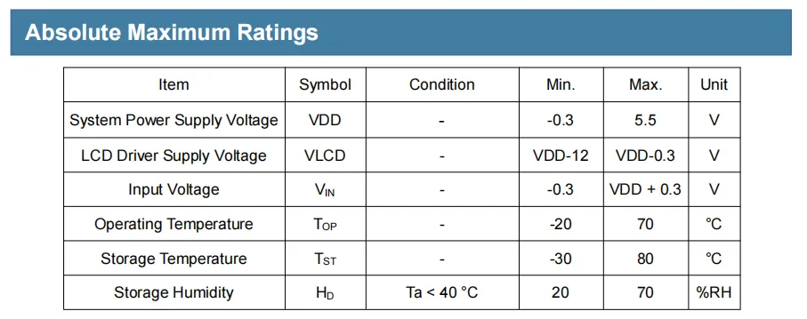
This table presents LCM1602A-14 liquid crystal module's absolute maximum ratings, which define its limiting operating and storage conditions:
- Voltage Range: System supply voltage
VDDranges from -0.3V to 5.5V,LCDdriving voltageVLCDshall be within the range ofVDD-12V toVDD-0.3V, and input voltageVINranges from -0.3V toVDD+ 0.3V; - Temperature and Humidity Range: Operating temperature: -20℃ to 70℃, storage temperature: -30℃ to 80℃; when the ambient temperature is lower than 40℃, the storage humidity shall be maintained between 20%
RHand 70%RH.
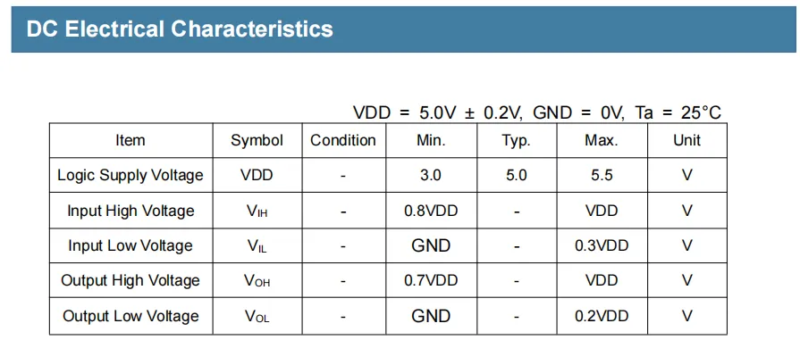
This table presents LCM1602A-14 the DC electrical characteristics of the liquid crystal module under the conditions of VDD = 5.0V±0.2V and ambient temperature of 25°C:
- Logic supply voltage
VDDranges from 3.0V to 5.5V, with a typical value of 5.0V; - Input high level
VIH≥ 0.8VDD, input low levelVIL≤ 0.3VDD; - Output high level
VOH≥ 0.7VDD, output low levelVOL≤ 0.2VDD.
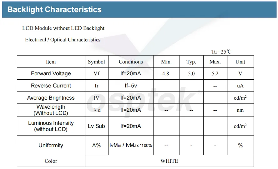
This table presents LCM1602A-14 liquid crystal module white light LED backlight's electrical and optical characteristics at 25℃: at a forward current of 20mA, the typical forward voltage is 5.0V (range: 4.8V~5.2V), the backlight color is white, and relevant parameters including reverse current, average luminance, emission wavelength, luminous intensity and luminance uniformity are also provided.
2.5 Reference Circuit
None.
2.6 Chip Configuration
None.
2.7 Communication Interfaces and Related Protocols
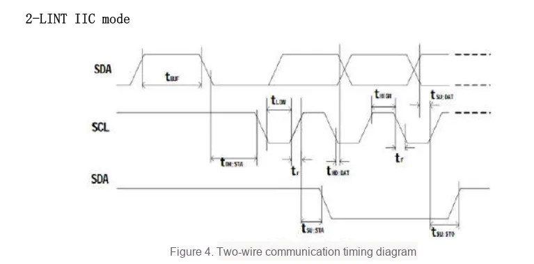
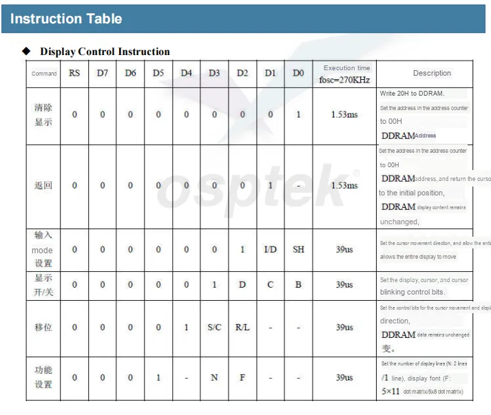
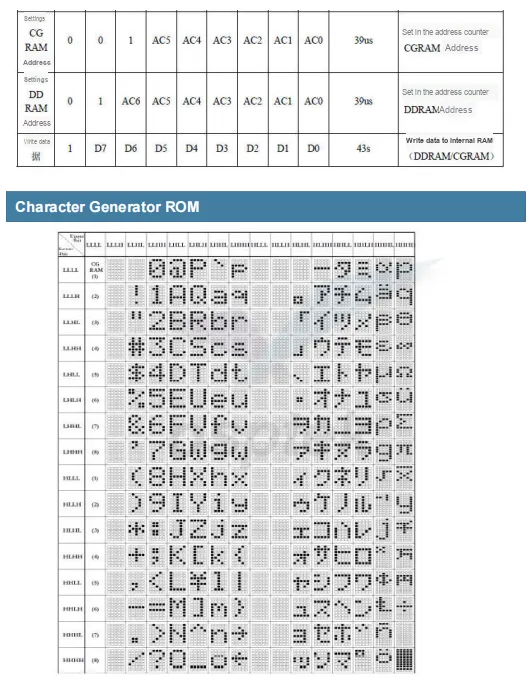
LCM1602A-14 module's serial communication timing, instruction set and font library resources: the two-wire I²C communication Sequence Diagram defines key time parameters such as start/stop, data setup/hold between SDA and SCL; the instruction list covers core control instructions including display clear, mode setting, display on/off, and specifies the register configuration and execution time of each instruction;Character generation ROM provides complete character dot matrix mappings for standards such as ASCII. Combined with the address setting and data write instructions for CGRAM / DDRAM, it realizes the complete process from serial communication to character display, providing a comprehensive basis for the driver development of the module.
2.8 PCB Routing Precautions
None.
III. Circuit Engineering
3.1 Circuit Source Engineering
To obtain the circuit source project, please follow the official account [Freak Embedded].
3.2 Module Usage Instructions
The schematic diagram of this module is shown below:
SCH_LCM1602A-14-Based LCD Module-V1.0.0_2026-03-31.pdf 2.2 MB
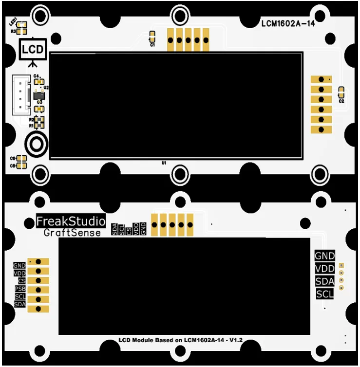
This module provides an IIC communication interface: it supports standard/fast I²C communication rates up to 400kHz, can be configured to I²C / PSB mode via the I²C pins, is compatible with 3.3V/5V logic levels, and can stably realize text and cursor display of 2 lines × 16 characters (5×8 dot matrix). Built with a 5V-to-3.3V DC-DC power supply circuit, power filtering and indicator circuit, it is suitable for scenarios requiring basic text display such as embedded development, maker projects and industrial instruments, and provides reliable low-power character interaction capability for the system.
3.3 Application Experiment
Here, we use the GraftPort-RP2040 development board for testing, and the liquid crystal display module based on LCM1602A-14 uses the I2C interface to communicate with the main controller.
Here, we first use the HY2.0-4P cable to connect the module to the GraftPort-RP2040 development board's I2C0 interface:
The module connections are shown in the following table:
Development Board Pins | Module Pins | Description |
Pin 4 |
|
|
Pin 5 |
|
|
Here, we need to search for the relevant driver packages on uPyPI: https://upypi.net/zh/
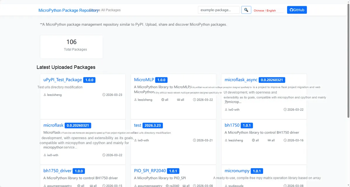
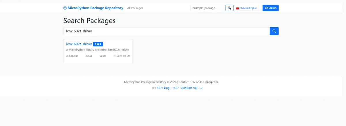
Enter lcm1602a_driver to search, and the following will be displayed:
Click to copy the local installation command:
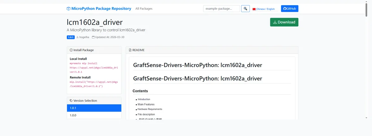
Import the module driver library code via the mip tool. Below are the usage commands for the mpremote tool:
mpremote mip install https://upypi.net/pkgs/lcm1602a_driver/1.0.0Import the LCD display module based on LCM1602A-14 - MicroPython driver code, then copy the following main.py code into our project:
# Python env   : MicroPython v1.23.0
# -*- coding: utf-8 -*-
# @Time    : 2026/3/13 5:00 PM
# @Author  : bhavi-thiran
# @File    : main.py
# @Description : Drive an LCD1602 display over the I2C interface, implementing core functions such as display control, cursor management, and character output

# ======================================== Import Modules =========================================
# Import everything related to the LCD1602 display I2C driver
from LCD_I2C import LCD

# Import the I2C class (for I2C bus configuration) and the Pin class (for pin configuration) from the machine module
from machine import I2C, Pin

# Import the time module (for delays and waiting at program start)
import time

# ======================================== Global Variables ============================================
# I2C SCL pin number
I2C_SCL_PIN = 5
# I2C SDA pin number
I2C_SDA_PIN = 4
# I2C communication frequency (Hz)
I2C_FREQ = 400000
# Common I2C target addresses of the LCD1602 (decimal: 39=0x27, 62=0x3E)
TARGET_LCD_ADDRS = [39, 62]

# ======================================== Functions ============================================

# ======================================== Custom Classes ============================================

# ======================================== Initialization configuration ===========================================
# Program start delay of 3 seconds to ensure the hardware has finished initializing
time.sleep(3)
# Print a function identifier indicating that the current function is controlling the LCD1602 display via I2C
print("FreakStudio: Control LCD1602 via I2C")

# Initialize I2C bus 0
i2c_bus = I2C(0, scl=Pin(I2C_SCL_PIN), sda=Pin(I2C_SDA_PIN), freq=I2C_FREQ)

# Start scanning for devices on the I2C bus
devices_list: list[int] = i2c_bus.scan()
print("START I2C SCANNER")

# Check the I2C device scan result
if len(devices_list) == 0:
    print("No i2c device !")
    raise SystemExit("I2C scan found no devices, program exited")
else:
    print("i2c devices found:", len(devices_list))

# Iterate through the address list to initialize the target LCD1602
lcd = None  # Placeholder for the LCD object
for device in devices_list:
    if device in TARGET_LCD_ADDRS:
        print("I2c hexadecimal address:", hex(device))
        try:
            # Target address found, initialize the LCD object
            lcd = LCD(i2c_bus)
            print("LCD1602 initialization successful")
            break
        except Exception as e:
            print(f"LCD1602 Initialization failed: {e}")
            continue
else:
    # All devices traversed without finding the target address, raise a clear exception
    raise Exception("No LCD1602 device found in I2C bus (target addresses: 0x27/0x3E)")

# ========================================  Main Program  ============================================
# Set the LCD1602 cursor position to row 0, column 0
lcd.set_cursor(0, 0)
# Write the string "Hello World" at the current cursor position
lcd.write("Hello World")
# Delay 1 second to keep the displayed content for 1 second
time.sleep(1)

# Turn off the display function of the LCD1602
lcd.off()
# Delay 1 second to keep the off state for 1 second
time.sleep(1)

# Turn on the display function of the LCD1602
lcd.on()
# Delay 1 second to keep the on state for 1 second
time.sleep(1)

# Turn on the LCD1602 display, turn off the cursor display, turn on cursor blinking
lcd.on(cursor=False, blink=True)
# Delay 1 second to keep this display state for 1 second
time.sleep(1)

# Turn on the LCD1602 display, turn on the cursor display, turn off cursor blinking
lcd.on(cursor=True, blink=False)
# Delay 1 second to keep this display state for 1 second
time.sleep(1)

# Turn on the LCD1602 display, turning on both the cursor display and cursor blinking
lcd.on(cursor=True, blink=True)
# Delay 1.5 seconds to keep this display state for 1.5 seconds
time.sleep(1.5)

# Clear all content shown on the LCD1602 display
lcd.clear()
Burn the code, open the terminal, and the output is as follows:
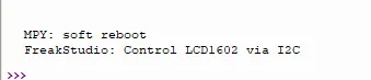
A basic demo program that implements device scanning initialization, text display, screen on/off, cursor/blink control, and screen clearing.
IV. Drivers
lcm1602a_driver-1.0.2.zip 13 KB
5. BOM & Recommended Alternative Parts
None.
VI. Revision History
Document Version | Date Modified | Modifier | Modify Content |
v1.0 | 2026-03-26 | Ling Gaoxing | Initialize the document |
v1.0.1 | 2026-04-21 | Li Zisheng | The production documents have not been exported yet, and all the rest have been sorted out. |
v1.1 | 2026-04-23 | Xin Ruili | Create an open version of the document, based on the internal document version v1.0.1. |
7. Relevant Materials
7.1 Chip Datasheet
LCM_1602_A_14_69c024ac07.pdf 858 KB
7.2 Unique Icons for PCB Silk Screen