Contents
- I. Module Introduction
- II. Introduction to Main Chips
- 2.1 Chip Overview
- 2.2 Pin Definition
- 2.3 Functional Block Diagram
- 2.4 Performance Parameters
- 2.5 Reference Circuit
- 2.6 Chip Configuration
- 2.7 Communication Interfaces and Related Protocols
- 2.8 PCB Routing Precautions
- III. Circuit Engineering
- 3.1 Circuit Source Engineering
- 3.2 Module Usage Instructions
- 3.3 Application Experiment
- IV. Drivers
- 5. BOM & Recommended Alternative Parts
- VI. Revision History
- 7. Relevant Materials
- 7.1 Chip Datasheet
- 7.2 Unique Icons for PCB Silk Screen
I. Module Introduction
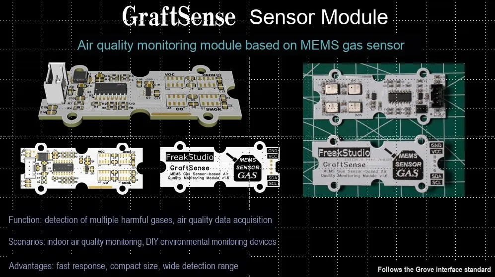
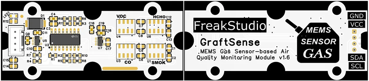
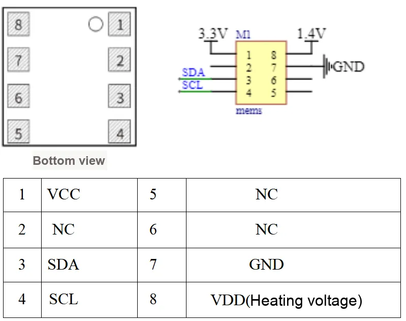
Based on the MEMS gas sensor-based air quality monitoring module, which adopts I2C communication and is equipped with the PCA9546ADR multiplexer chip, can be connected to 4 types of gas sensors for smoke, carbon monoxide, VOC and formaldehyde. Powered by 5V input which is stepped down to 3.3V and 1.4V to supply power for the sensors and internal heating respectively, it integrates circuits including power filtering, indication and MCU interface, capable of monitoring multiple gases, and is applicable to scenarios related to air quality monitoring.
II. Introduction to Main Chips
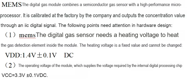
An I2C expansion chip PCA9546ADR is used to connect four gas detection sensors respectively, which are smoke sensor (JED115), carbon monoxide sensor (JED104), VOC sensor (JED101) and formaldehyde sensor (JED116).
2.1 Chip Overview
2.2 Pin Definition
2.3 Functional Block Diagram
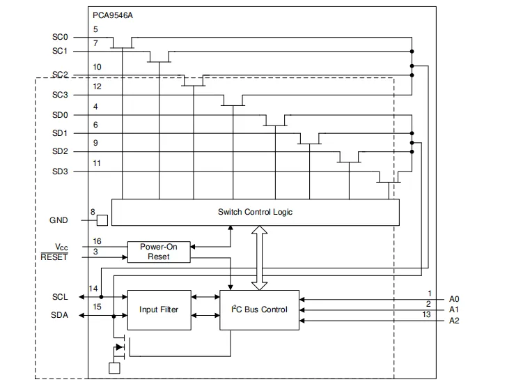
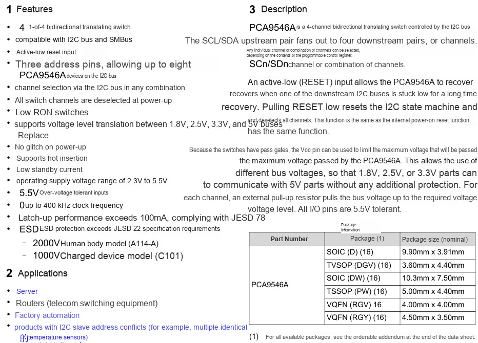
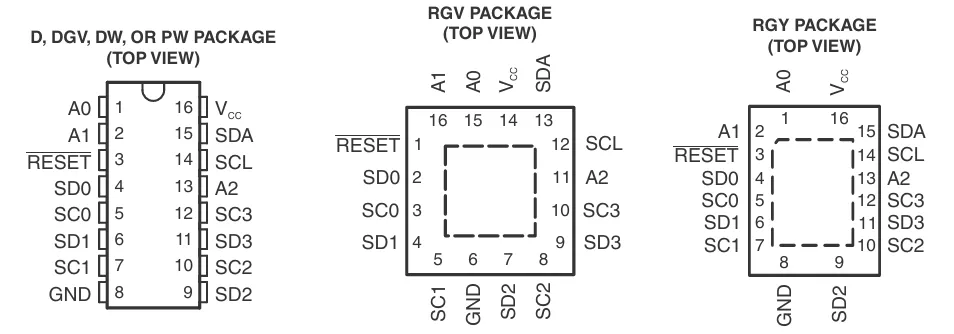
This is the internal functional block diagram of the PCA9546A chip, which is an I²C bus multiplexer designed to expand I²C bus channels. It enables connecting multiple slave devices to a single I²C bus, supporting time-division switching control for multiple I²C devices. The functions of each module are explained as follows:
I²C Bus Control(I²C Bus Control Module): responsible for processing theI²Cbus's Communication Protocol, interacting with external master devices (such as MCUs) viaSCL(clock line, Pin 14) andSDA(data line, Pin 15), while receiving inputs from the address pinsA0(Pin 2),A1(Pin 13), andA2(Pin 1) to configure the device address.Input Filter(Input Filter Module): Filters the input signals ofSCLandSDAto reduce noise interference and ensure the stability ofI²Ccommunication.Power-On Reset(Power-On Reset Module): When the chip is powered on, it generates a reset signal to initialize the internal logic of the chip, ensuring that the chip starts operating from a defined state.Switch Control Logic(switch control logic module): Controls the on/off state of the internal multiplexer according to the instructions from the I²C bus control module, so as to implement switching between differentI²Cchannels (SC0-SC3,SD0-SD3).- Multi-channel I²C channels (
SC0-SC3, SD0-SD3): These pins are used to connect externalI²Cslave devices. Through the switching of the switch control logic, the master device can establishI²Ccommunication with one of the slave devices. - Power Supply and Reset:
Vcc(Pin 16): Power supply input of the chip;GND(Pin 8): Ground;RESET(Pin 3): Reset input pin, through which a reset signal can be manually input to reset the chip.
2.4 Performance Parameters
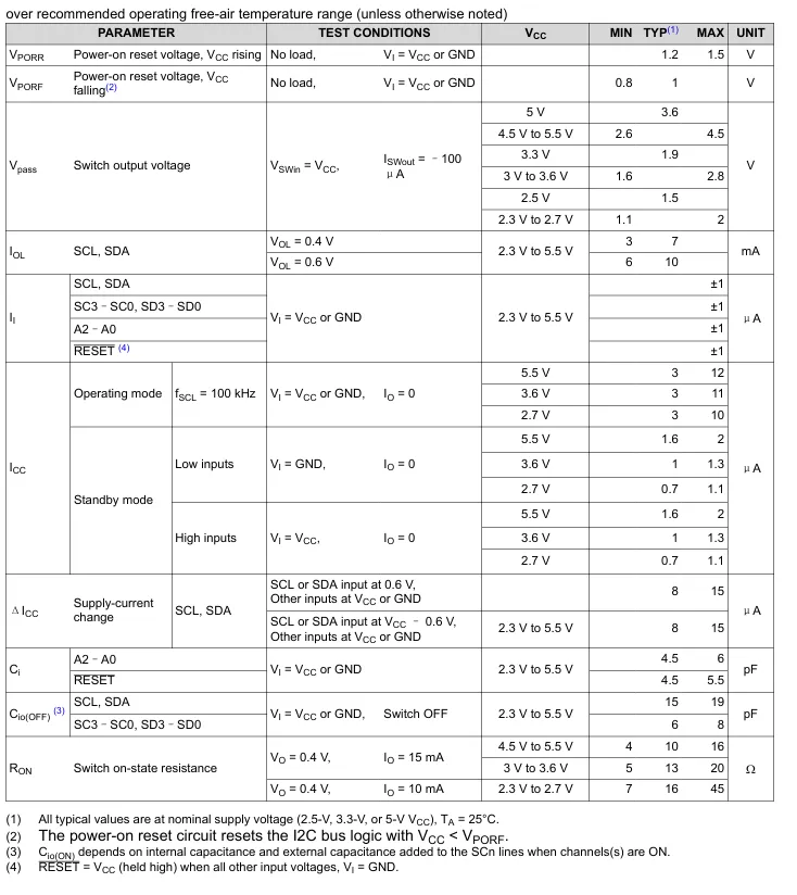
2.4.1 PCA9546A Performance Parameters
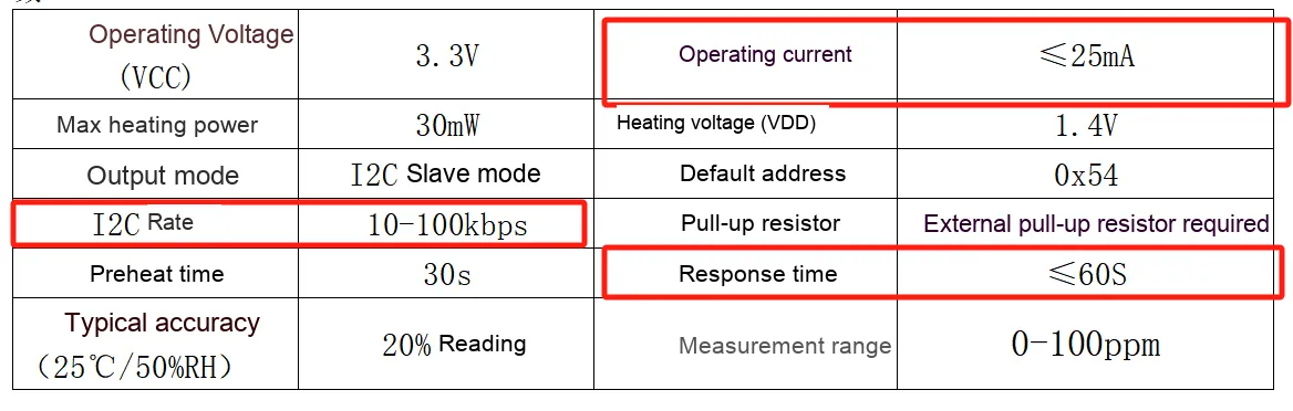
2.4.2 Formaldehyde Sensor (JED116) Performance Parameters
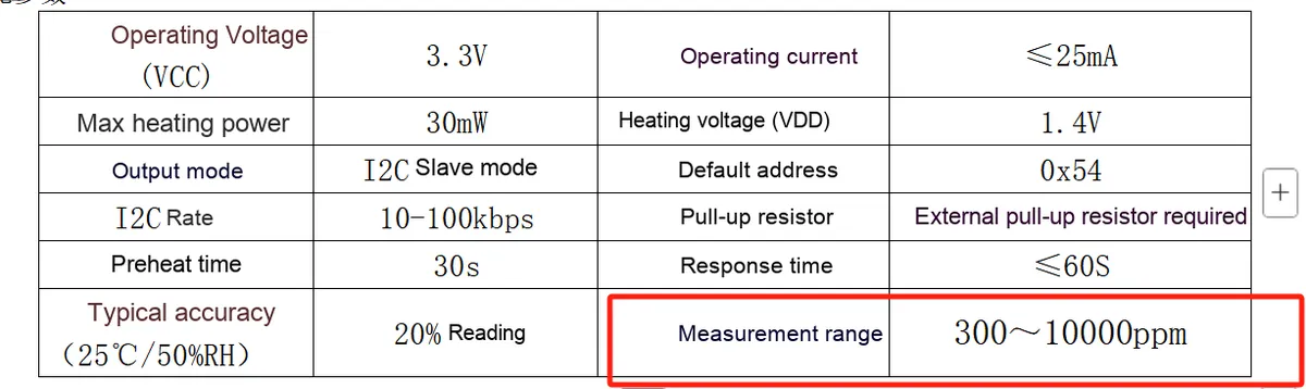
2.4.3 Smoke Sensor (JED115) Performance Parameters
2.4.4 Performance Parameters of VOC Sensor (JED101)
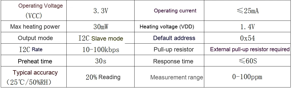
2.4.5 Carbon Monoxide Sensor (JED104) Performance Parameters
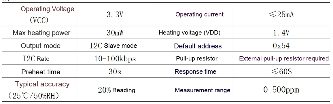
2.5 Reference Circuit
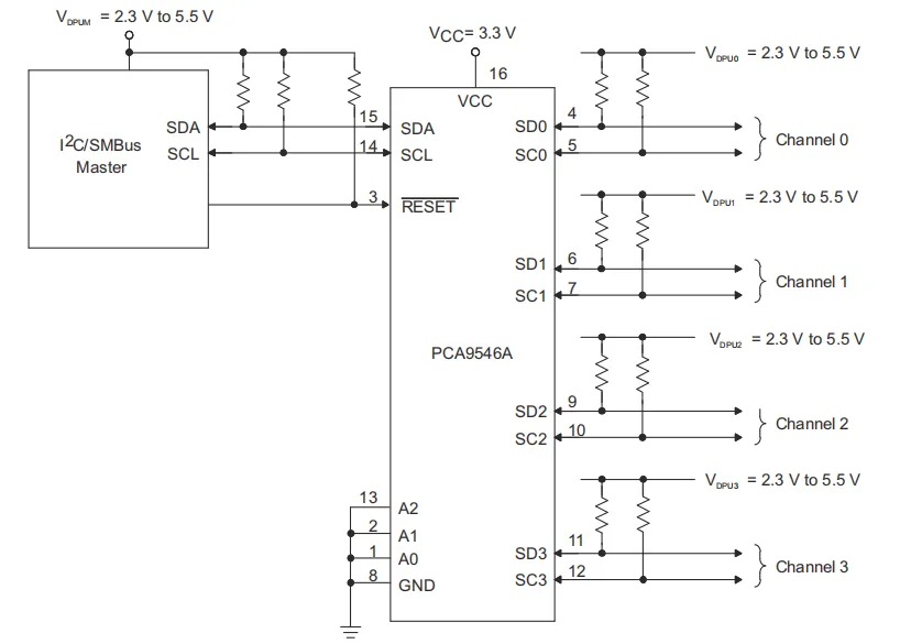
2.6 Chip Configuration
None.
2.7 Communication Interfaces and Related Protocols
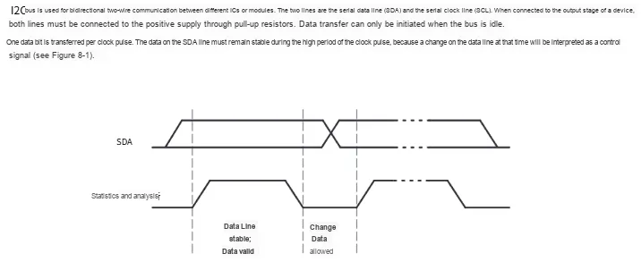
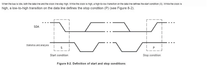
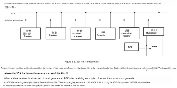
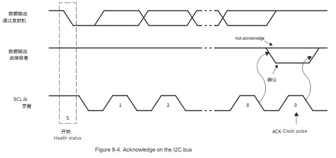
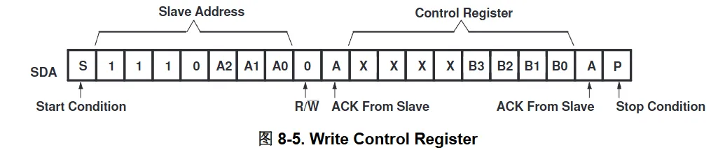
Data is transmitted to the PCA9546A control register using the write mode shown in Figure 8-5.
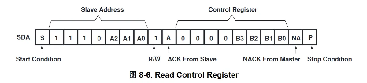
Use the read mode shown in Figure 8-6 to read data from the PCA9546A control register.
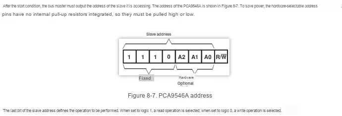
Device Address:
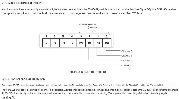
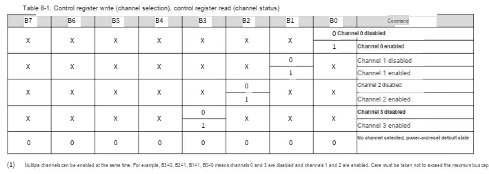
2.8 PCB Routing Precautions
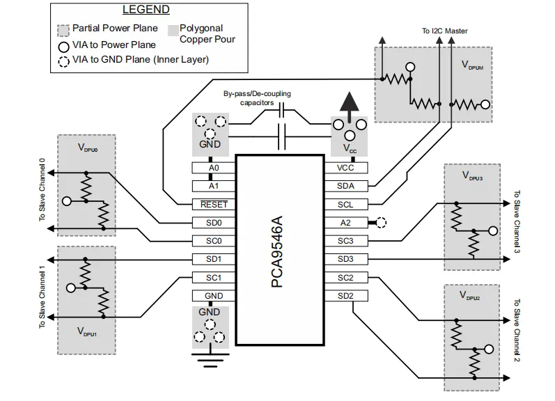
For the PCB layout of the PCA9546A, general PCB layout specifications shall be followed, and additional requirements related to high-speed I²C signals shall also be noted. Common PCB impedance and differential pairs are not a concern at I²C signal speeds. Typically, a dedicated ground plane is arranged in the inner layer of the circuit board, and pins connected to ground must form a low-impedance path to the ground plane by means of wide copper pours and multiple vias.Bypass capacitors and decoupling capacitors are commonly used to control the voltage ripple at the V₍₆₆₎ pin: larger capacitors provide additional power during short-term power supply fluctuations, while smaller capacitors are used to filter out high-frequency ripple.
In applications where voltage conversion is not required, all V₍ₚₙₓ₎ voltages and V₍₆₆₎ can be at the same potential, and a single copper layer can connect all pull-up resistors to the corresponding reference voltage. In applications where voltage conversion is required, V₍ₚᵤₗₗ₋ₚₒₛ₎, V₍ₚᵤₗₗ₋ₙₑ₉₎, V₍ₚᵤₗₗ₋ᵤₚ₎, V₍ₚᵤₗₗ₋ₙₒᵣₘₐₗ₎ and V₍ₚᵤₗ₋ₙₑ₉₎ can all be located on the same copper layer, with split planes isolating different voltage potentials.
To reduce the total capacitance of the I²C bus when adding PCB parasitic capacitance, the data lines (SCN and SDN) must be as short as possible, and the trace width must also be minimized (e. g., 5-10 mils selected according to the copper weight).
III. Circuit Engineering
3.1 Circuit Source Engineering
To obtain the source code of the circuit, please follow the official account [Freak Embedded]
3.2 Module Usage Instructions
The schematic diagram of this module is shown below:
SCH_Air Quality Monitoring Module Based on MEMS Gas Sensor_v1.6_2026-04-05.pdf 2.6 MB
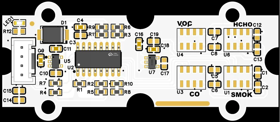
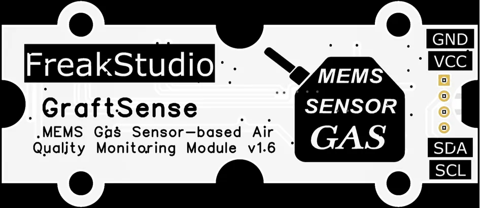
This module has an I2C communication interface, using an I2C expansion chip PCA9546A can mount four gas sensors smoke sensor ( JED115 ), carbon monoxide sensor ( JED104 ), VOC sensor ( JED101 ) and formaldehyde sensor ( JED116 ), we can use the MCU interface connected to the I2C communication interface for communication, sequentially switching I2C expansion chip PCA9546A different I2C channels and gas sensors for communication.
Please note during use: zero calibration must be performed in advance in the air!!!
3.3 Application Experiment
Here, we use the GraftPort-RP2040 development board for testing, and the MEMS gas sensor-based air quality monitoring module uses the I2C interface to communicate with the main controller.
Here, we first use the HY2.0-4P cable to connect the module to the GraftPort-RP2040 development board's I2C0 interface:
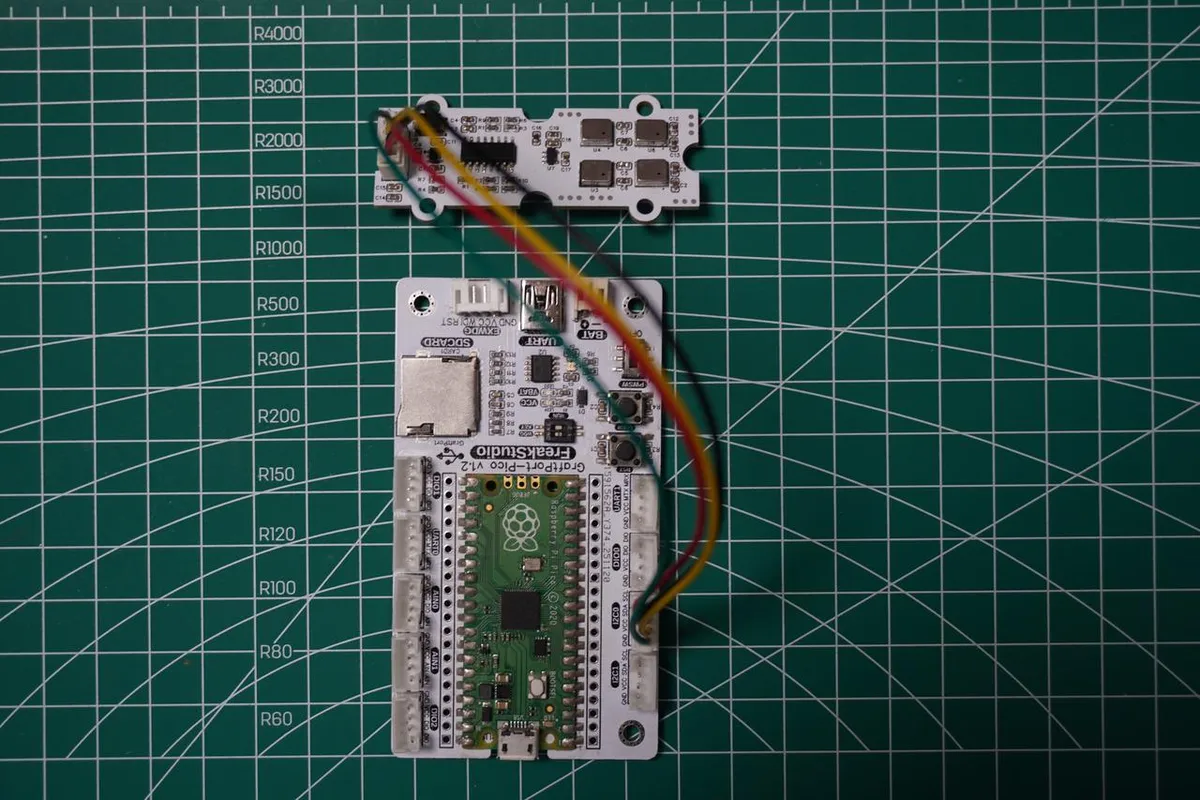
The module connections are shown in the following table:
Development Board Pins | Module Pins | Description |
Pin 4 |
|
|
Pin 5 |
|
|
Here, we need to search for the relevant driver packages on uPyPI: https://upypi.net/zh/
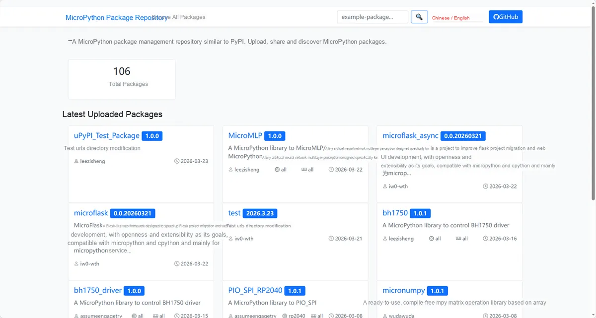
Enter mems_driver to search, and the following will be displayed:

Click to copy the local installation command:
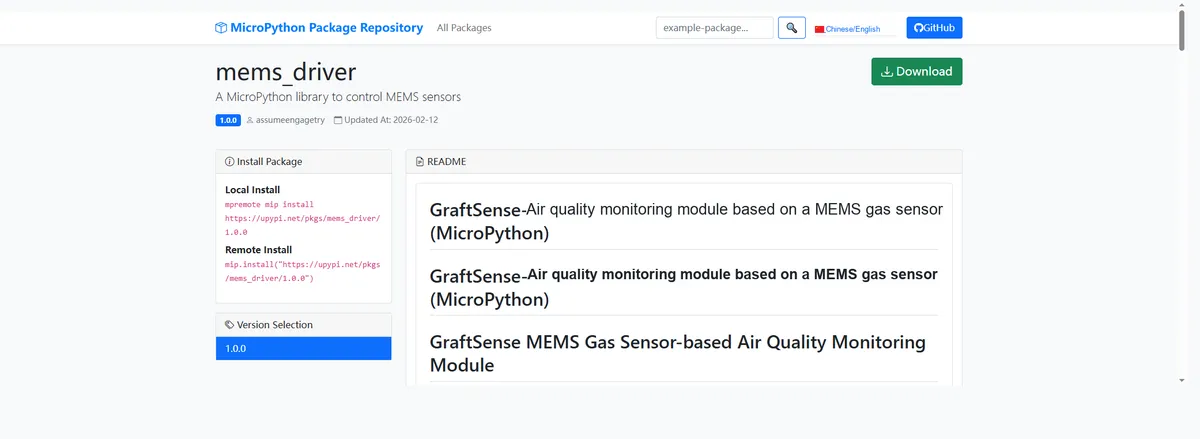
Here, we can import the module driver library code via the mip tool. The usage commands for the mpremote tool are as follows:
mpremote mip install github:FreakStudioCN/GraftSense-Drivers-MicroPython/sensors/mems_driverImport the air quality monitoring module based on MEMS gas sensor - MicroPython driver code, then copy the following main.py code into our project:
# Python env   : MicroPython v1.23.0
# -*- coding: utf-8 -*-
# @Time    : 2025/12/22 PM 2:21
# @Author  : hogeiha
# @File    : main.py
# @Description : MEMS gas sensor multi-channel reading example code, implementing calibration and real-time concentration reading for four gases: VOC/CO/H2S/NO2

# ======================================== Import Modules =========================================

from machine import Pin, SoftI2C
import time
from mems_air_module import MEMSGasSensor, PCA9546ADR, AirQualityMonitor

# ======================================== Initialization ==========================================

# Delay to wait for the device to initialize
time.sleep(3)
# Print debug information
print("FreakStudio : Using IIC to read MEMS sensor")

i2c = SoftI2C(sda=Pin(4), scl=Pin(5), freq=100000)


monitor = AirQualityMonitor(i2c)


# Channel 0: VOC sensor registration and calibration
print("Registering and calibrating VOC sensor on channel 0...")
monitor.register_sensor(0, MEMSGasSensor.TYPE_VOC)
monitor.calibrate_sensor(MEMSGasSensor.TYPE_VOC)

# Channel 1: CO sensor registration and calibration
print("Registering and calibrating CO sensor on channel 1...")
monitor.register_sensor(1, MEMSGasSensor.TYPE_CO)
monitor.calibrate_sensor(MEMSGasSensor.TYPE_CO)

# Channel 2: H2S sensor registration and calibration
print("Registering and calibrating H2S sensor on channel 2...")
monitor.register_sensor(2, MEMSGasSensor.TYPE_H2S)
monitor.calibrate_sensor(MEMSGasSensor.TYPE_H2S)

# Channel 3: NO2 sensor registration and calibration
print("Registering and calibrating NO2 sensor on channel 3...")
monitor.register_sensor(3, MEMSGasSensor.TYPE_NO2)
monitor.calibrate_sensor(MEMSGasSensor.TYPE_NO2)

# ======================================== Main Program =============================

print("\nStart reading gas concentration (press Ctrl+C to stop)...")
print("-" * 50)

while True:
    try:
        # Read the concentration values of all registered sensors and return a {sensor type: concentration} dictionary
        results = monitor.read_all()

        # Print the formatted gas concentration values
        print(f"VOC concentration: {results[MEMSGasSensor.TYPE_VOC]}")
        print(f"CO concentration: {results[MEMSGasSensor.TYPE_CO]}")
        print(f"H2S concentration: {results[MEMSGasSensor.TYPE_H2S]}")
        print(f"NO2 concentration: {results[MEMSGasSensor.TYPE_NO2]}")
        print("-" * 50)

    except Exception as e:
        # Catch and print all exceptions to avoid program crashes
        print(f"Error reading concentration: {str(e)}")
        print("-" * 50)

    # Read data once every 1 second
    time.sleep(1)
When flashing the code, the terminal output is as follows:
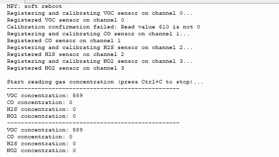
IV. Drivers
mems_driver-1.0.1.zip 13 KB
5. BOM & Recommended Alternative Parts
None.
VI. Revision History
Document Version | Date Modified | Modifier | Modify Content |
v1.0 | 2025-10-24 | Ling Gaoxing | Initialize the document |
v1.1 | 2025-12-29 | Li Zisheng | Added application experiments and production files |
v1.2 | 2026-03-29 | Xin Ruili | Modified the application experiment section |
v1.3 | 2026-04-05 | Li Zisheng | Update the circuit engineering to v1.6, The cover photo has not been taken, the production files have not been exported yet, and all other items have been sorted out. |
v1.4 | 2026-04-21 | Li Zisheng | The production documents have not been exported yet, and all the rest have been sorted out. |
v1.5 | 2026-04-29 | Xin Ruili | Create an open version of the document based on the internal document version v1.4. |
7. Relevant Materials
7.1 Chip Datasheet
MEMS Digital Design Guide.doc 671 KB
MEMS Digital Smoke Sensor JED115-001.docx 452 KB
I2C Multiplexer_PCA9546ADR(UMW)_Datasheet_UMW+PCA9546.PDF 1.7 MB
MEMS Digital CO Sensor JED104-001.docx 452 KB
MEMS Digital VOC Sensor JED101-001.docx 452 KB
MEMS Digital Formaldehyde Sensor JED116-001.docx 452 KB
7.2 Unique Icons for PCB Silk Screen