Contents
- I. Module Introduction
- II. Introduction to Main Chips
- 2.1 Chip Overview
- 2.2 Pin Definition
- 2.3 Functional Block Diagram
- 2.4 Performance Parameters
- 2.5 Reference Circuit
- 2.6 Chip Configuration
- 2.7 Communication Interfaces and Related Protocols
- 2.8 PCB Routing Precautions
- III. Circuit Engineering
- 3.1 Circuit Source Engineering
- 3.2 Module Usage Instructions
- 3.3 Application Experiment
- IV. Drivers
- 5. BOM & Recommended Alternative Parts
- VI. Revision History
- VII. Relevant Materials
- 7.1 Chip Datasheet
- 7.2 Unique Icons for PCB Silk Screen
I. Module Introduction
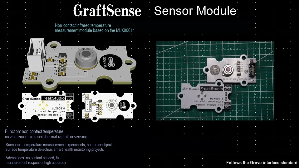
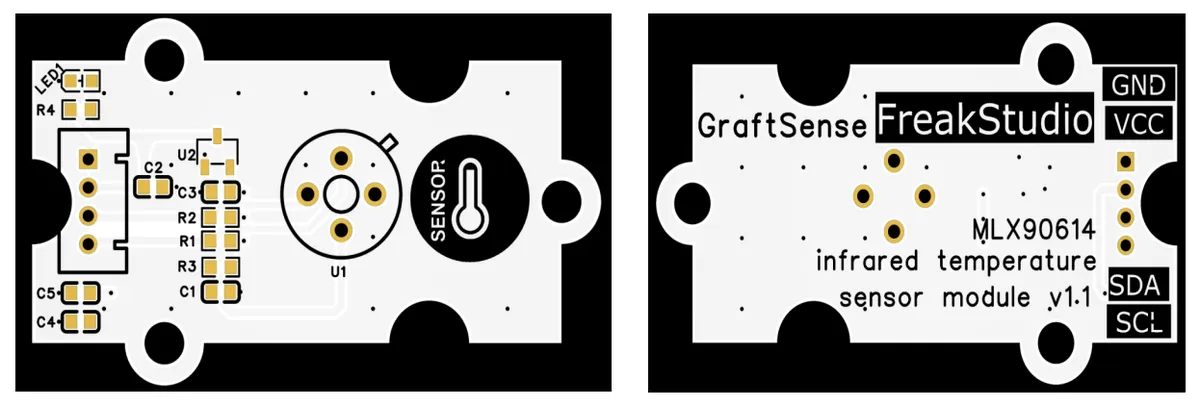
The non-contact infrared temperature module based on MLX90614 is a medical-grade digital infrared temperature sensor built around the MLX90614 chip. This module integrates an infrared thermopile detector, a low-noise amplifier, a 17-bit high-precision ADC, and a digital signal processor; it can directly output calibrated temperature values via the I²C communication interface, eliminating the need for complex peripheral circuit design and signal processing.This module features high measurement accuracy, fast response speed, small size, low cost and other advantages, and is suitable for application scenarios such as high-precision non-contact temperature measurement, automotive air conditioning control, smart home, microwave ovens, industrial temperature control, and medical equipment. The operating voltage range of the module is 3.3V to 5V, the measurement temperature range is −40°C to 300°C, and the accuracy can reach ±0.2°C within the range of 0°C to 50°C.
II. Introduction to Main Chips
2.1 Chip Overview
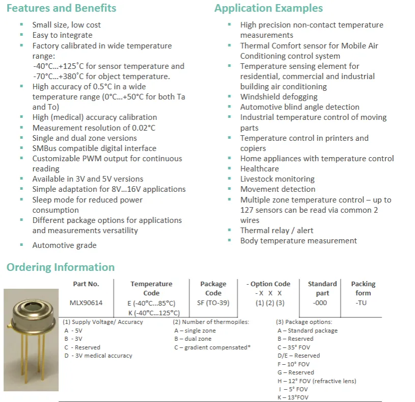
MLX90614 is a compact, low-cost non-contact temperature measurement chip that features easy integration, a wide operating Scope of Work (sensor: -40 to + 125℃, target: -70 to + 380℃), high accuracy (0.5℃) and high resolution (0.02℃), supports SMBus / PWM interfaces, multi-voltage versions and low-power modes, and also offers multiple package options and AEC-Q100 qualified grades; it can be applied in various scenarios including high-precision temperature measurement, air conditioning / home appliance / industrial temperature control, medical treatment, and automotive devices, and also supports multi-zone temperature control via multi-sensor networking.
2.2 Pin Definition
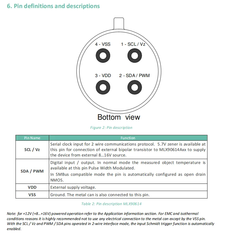
MLX90614 adopts a 4-pin package (bottom view), and the functions of each pin are as follows: Pin 1 SCL / Vz serves as the serial clock input for 2-wire communication, and can also be powered by an external power supply via a 5.7V Zener diode; Pin 2 SDA / PWM is a digital interface that outputs the target temperature in PWM format in normal mode, and acts as an open-drain SMBus bidirectional interface with NMOS in SMBus mode; Pin 3 VDD is the external power supply pin; Pin 4 VSS is the ground pin, and the metal shell of the chip also needs to be connected to this pin.Additionally, please note that the 12V power supply shall refer to the application notes, and the metal enclosure is only recommended to be connected to VSS.
2.3 Functional Block Diagram
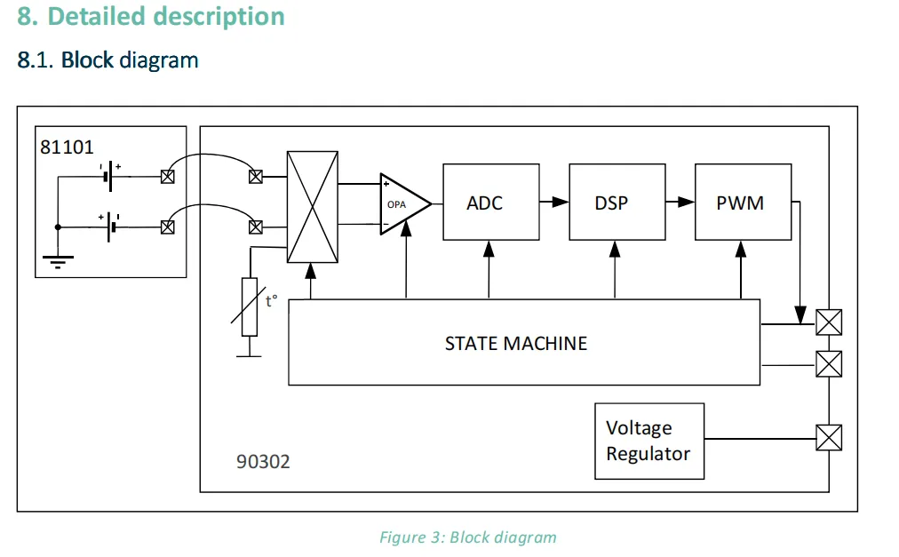
MLX90614 functional block diagram covers the core process of its temperature measurement operation: the 81101 thermopile sensor collects the infrared thermal signals of the target and the environment, combines the ambient temperature data obtained by the internal temperature sensor (t°), first undergoes front-end circuit processing, CPA amplification, then is converted into a digital signal by the ADC, after which data calculation is completed via the DSP, and finally the result is output through the PWM module; meanwhile, the finite-state machine is responsible for coordinating the working logic of each module, the voltage regulator provides stable power supply, and the whole system realizes the entire process of signal acquisition, processing and output for non-contact temperature detection.
2.4 Performance Parameters
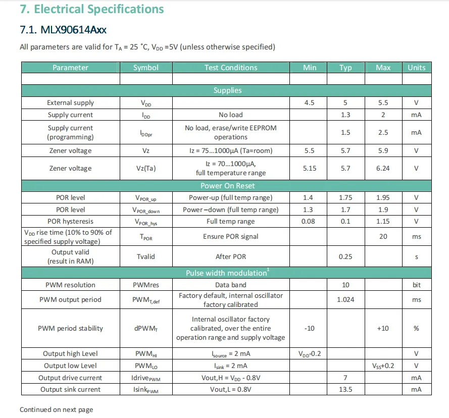
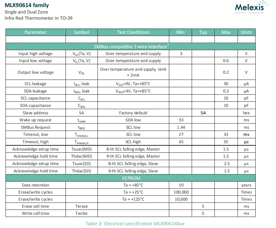
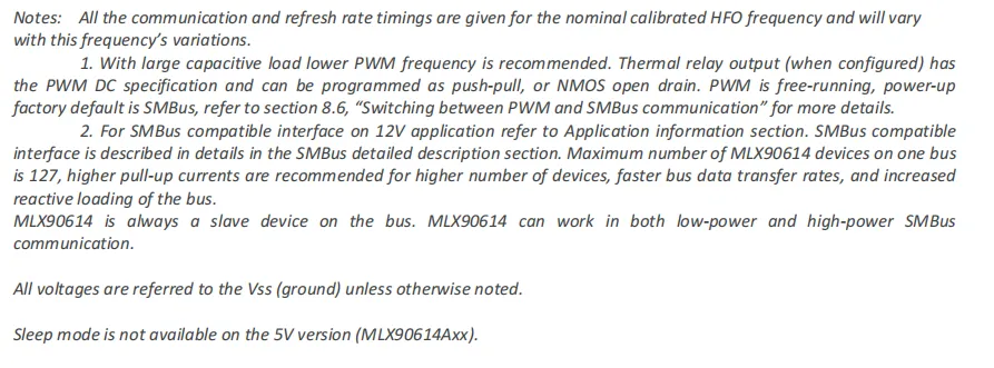
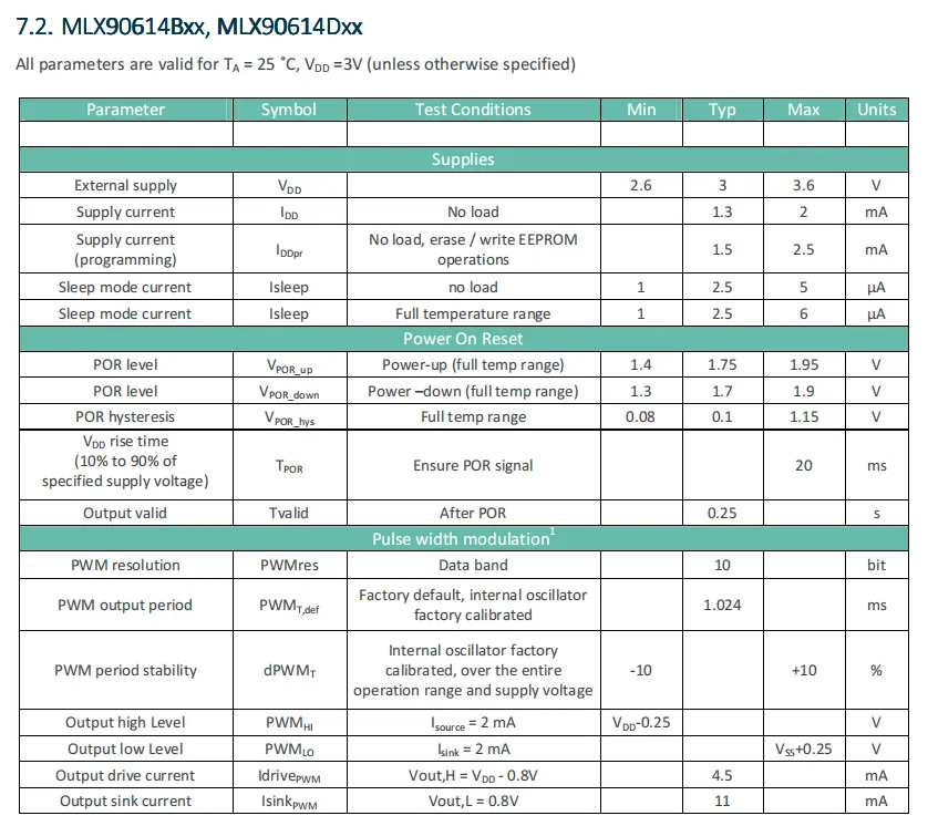
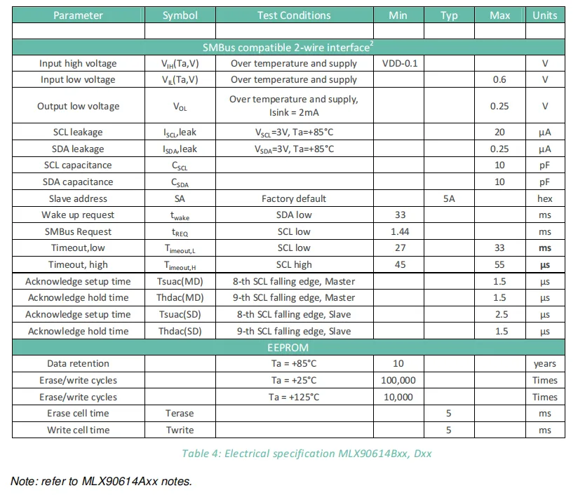
MLX90614 is available in 5V (Axx), 3V (Bxx / Dxx) versions, with respective supply voltage ranges of 4.5-5.5V/2.6-3.6V and operating current of approximately 1.3-2mA; it should be noted that the 5V version has no sleep mode, while the 3V version features a sleep current as low as 2.5μA. PWM has a resolution of 10bit and a period of 1.024ms, but its frequency is recommended to be reduced for large capacitive loads;SMBus interface has a default address of 5A (hexadecimal), up to 127 devices can be connected to a single bus, and attention should be paid to its leakage current and pin capacitance parameters.EEPROM data can be retained for 10 years, with up to 100,000 erase/write cycles at 85°C, but only 10,000 cycles at 125°C, and the erase/write time per packet is uniformly 5ms; meanwhile, all voltage parameters are referenced to VSS, and the timing parameters of power-on reset (POR) shall match the circuit design.
2.5 Reference Circuit
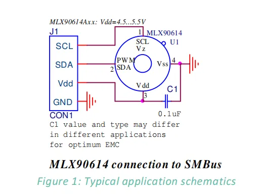
The reference circuit is a typical connection scheme for interfacing MLX90614 (5V version, Axx) with SMBus: Pin 1 (SCL / Vz) and Pin 2 (SDA / PWM) of the chip are connected to the clock (SCL) and data line (SDA) of the external SMBus respectively; Pin 3 (Vdd) is connected to a 4.5-5.5V power supply, and Pin 4 (Vss) is grounded; a 0.1μF capacitor C1 and Vdd and Vss for power supply decoupling and electromagnetic compatibility optimization (the parameters of C1 can be adjusted as required in different applications).Overall, it provides basic and practical connections for chip power supplies and communication interfaces, and is compatible with SMBus communication scenarios.
2.6 Chip Configuration
None.
2.7 Communication Interfaces and Related Protocols
2.7.1 SMBus Communication Protocol
MLX90614 's SMBus is a 2-wire Communication Protocol based on the SCL, PWM / SDA pins: it only functions as a slave, which needs to be selected by the master via the slave address (default 5A), supports two commands of Read Word / Write Word, and the master can read and write its RAM and part of EEPROM;SCL serves as the clock input (doubling as auxiliary for external voltage regulation), PWM / SDA is a bidirectional port (forced to open-drain in SMBus mode); up to 127 devices can be connected to the single bus, the 3V version can be switched to sleep mode via host commands, yet it only supports 2 standard commands of SMBus (most commands are not supported).
SMBus differs from standard I2C in the following aspects: SMBus is built on I2C, but features stricter voltage and timing constraints (including a timeout mechanism), a dedicated command set and address specifications, with a greater focus on power management;I2C, by contrast, has looser timing requirements, more flexible and general-purpose commands, and no mandatory timeout or power management restrictions.
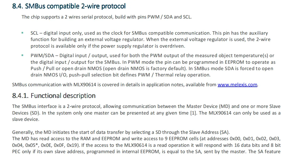
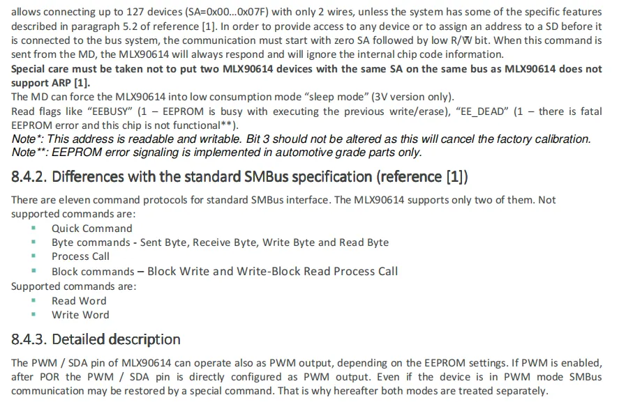
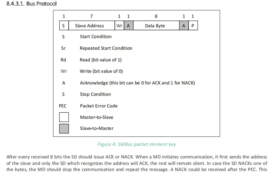
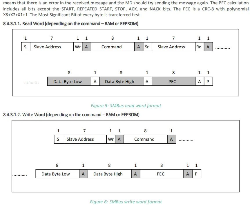
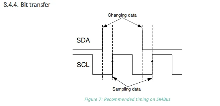

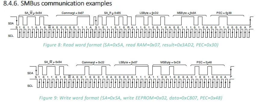
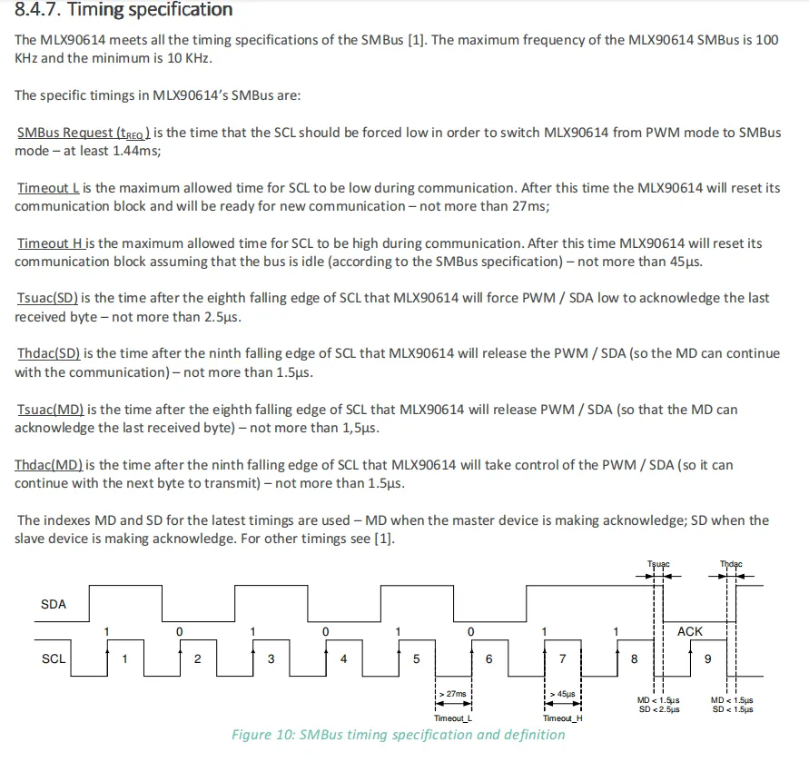
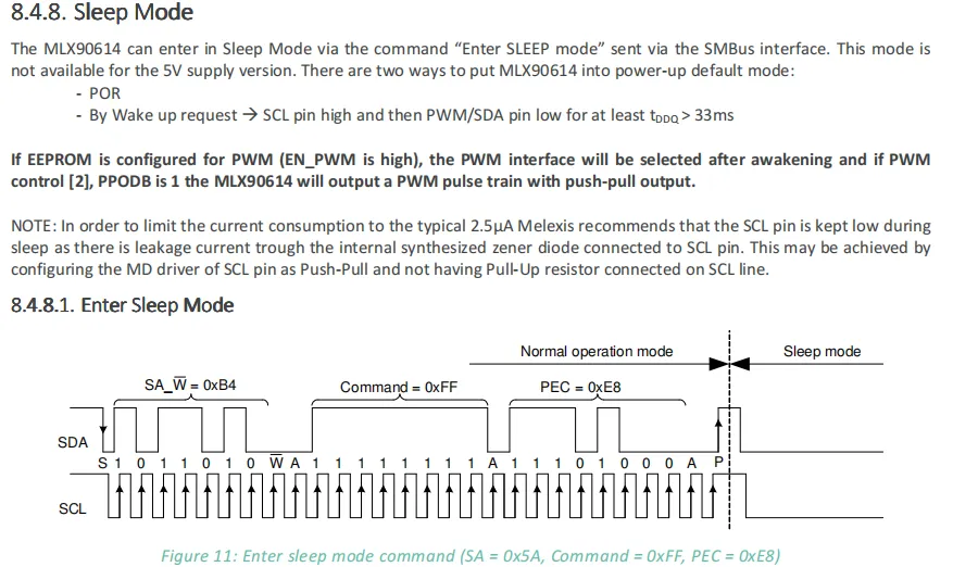
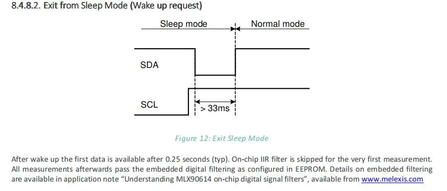
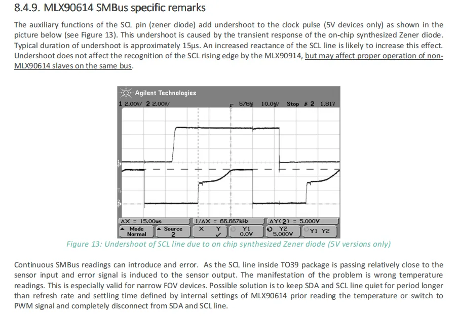
This section describes the MLX90614 SMBus -related details: it first defines bus packet elements (such as start/repeated start, read/write bits, acknowledge, etc.), specifies that the slave must respond with ACK / NACK after receiving every 8 bits, remains silent if the address does not match, and the master must retransmit upon NACK; bit transmission requires changing SDA data when SCL is at low level, with sampling at the rising edge; it provides communication waveform examples for reading RAM and writing EEPROM; the SMBus timing range is 10-100kHz, including parameters such as mode switching and timeout;Sleep mode is only supported by the 3V version, and is entered via SMBus commands; it can be woken up by POR or the condition " SCL high + SDA low for more than 33ms", and pulling SCL low during sleep can reduce power consumption;Finally, it is noted that for the 5V version, since SCL has undershoot due to the Zener diode, continuous SMBus reads may interfere with temperature measurement, so the bus needs to be kept silent or switched to PWM mode.
2.8 PCB Routing Precautions
None.
III. Circuit Engineering
3.1 Circuit Source Engineering
To obtain the source code of the circuit, please follow the official account [Freak Embedded]
3.2 Module Usage Instructions
The schematic diagram of this module is shown below:
SCH_Schematic1-MLX90614-Based Non-Contact Infrared Temperature Module-V1.1.pdf 2.2 MB
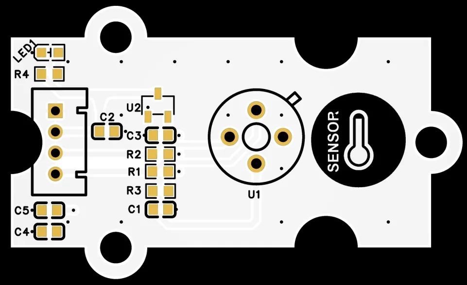
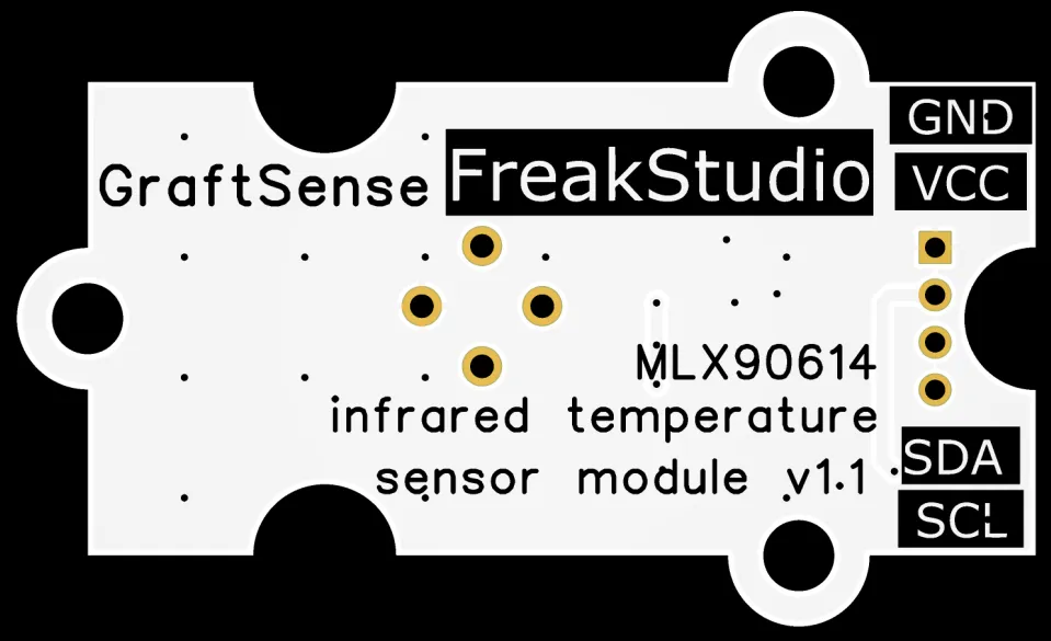
This module provides an I2C communication interface that supports a maximum I2C communication rate of 1MHz, with programmable slave address (default address: 0x33). The SDA and SCL interfaces feature 5V level tolerance, allowing direct connection to a 5V I2C network. Through this interface, users can not only read the calibrated temperature data output by the module but also access the device's internal registers to configure measurement parameters. It is compatible with the communication requirements of 3.3V/5V systems, providing convenient and stable connectivity support for device data interaction in high-precision non-contact temperature measurement scenarios.
3.3 Application Experiment
Here, we use the GraftPort-RP2040 development board for testing, and the non-contact infrared temperature module based on MLX90614 uses the I2C interface to communicate with the main controller.
Here, we first use the HY2.0-4P cable to connect the module to the GraftPort-RP2040 development board's I2C0 interface:
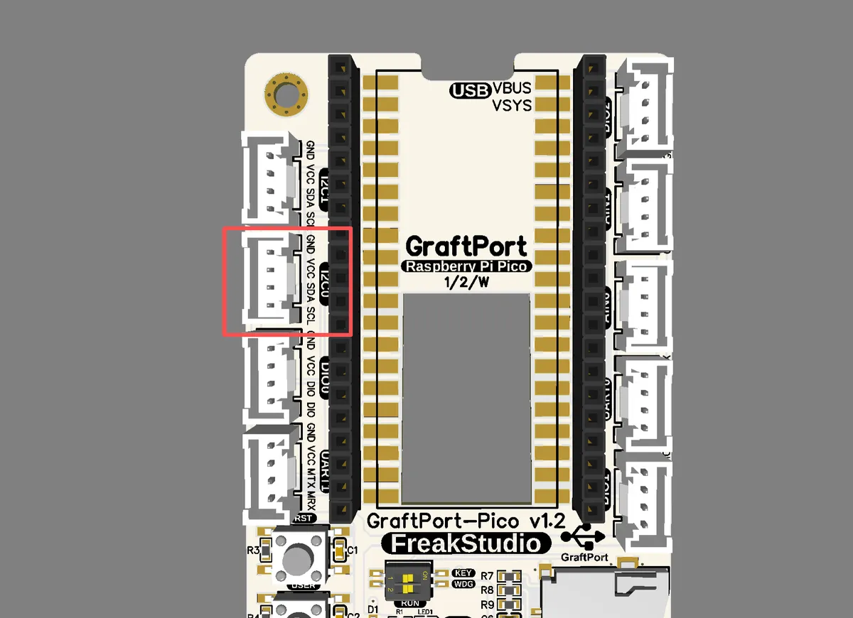
The module connections are shown in the following table:
Development Board Pins | Module Pins | Description |
Pin 4 |
|
|
Pin 5 |
|
|
Here, we need to search for relevant driver packages on uPyPI: https://upypi.net/zh/
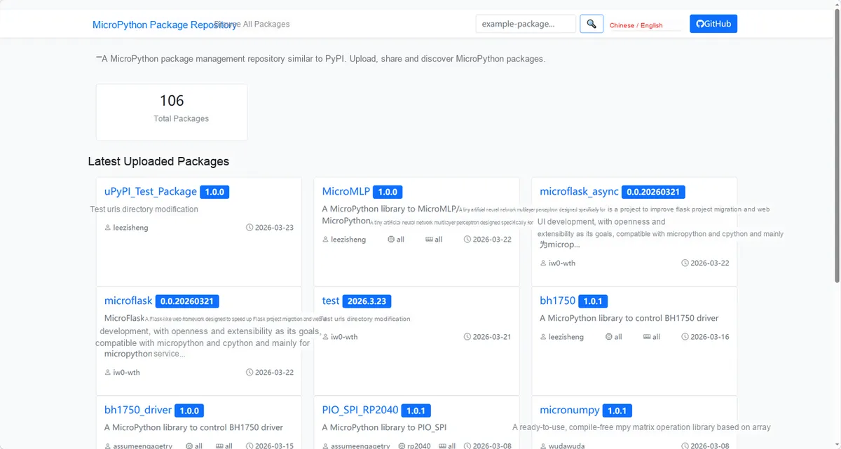
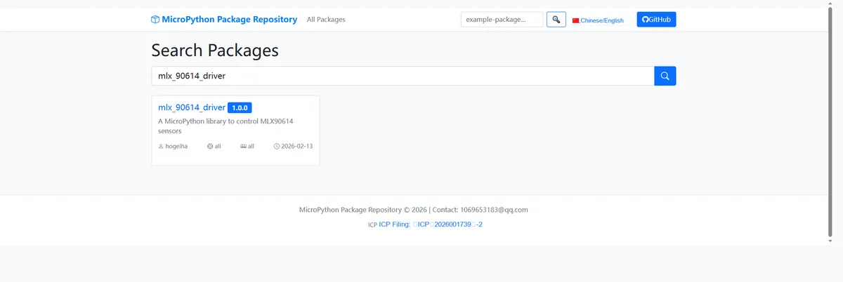
Enter mlx_90614_driver to search, and the following will be displayed:
Click to copy the local installation command:
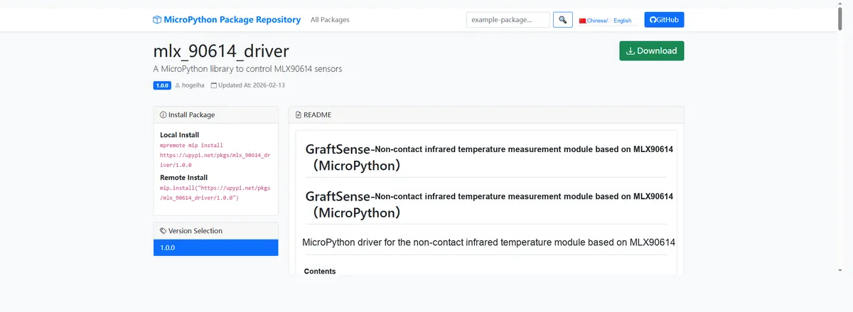
Here, we can use the mip tool to import module driver library code. Below are the usage commands for the mpremote tool:
mpremote mip install github:FreakStudioCN/GraftSense-Drivers-MicroPython/sensors/mlx_90614_driverImport the non-contact infrared temperature module based on MLX90614 - MicroPython driver code, then copy the following main.py code into our project:
# Python env   : MicroPython v1.23.0
# -*- coding: utf-8 -*-
# @Time    : 2025/8/27 11:50 AM
# @Author  : 缪贵成
# @File    : main.py
# @Description : mlx90614 dual-zone temperature sensor test file

# ======================================== Import Modules =========================================

import time
from machine import I2C, Pin
from mlx90614 import MLX90614, MLX90615

# ======================================== Global Variables =============================================

mlx61xaddr=None

# ======================================== Functions =============================================

def test_sensor_realtime(sensor, name="Sensor", interval=1.0):
    """

    Display sensor temperature data in real time, covering all function tests.
    Args:
        sensor: MLX90614 or MLX90615 sensor instance
        name: Sensor name, used for output labeling
        interval: Data refresh interval, in seconds

    Notes:
        The tests cover internal methods, public methods, property access, and one-shot read functionality
        Dual-zone sensors additionally display the second object temperature channel
        Internal method tests may vary depending on the sensor model

    ==========================================

    Realtime display of sensor temperature data, covering all functional tests.

    Args:
        sensor: Instance of MLX90614 or MLX90615 sensor
        name: Sensor name for output identification
        interval: Data refresh interval in seconds

    Notes:
        Tests include internal methods, public methods, property access and one-time read function
        Dual-zone sensors will additionally display the second object temperature data
        Internal method tests may vary by sensor model
    """
    print("\n=== Realtime testing {} ===".format(name))
    print("Dual zone:", sensor.dual_zone)  # Output whether the sensor is dual-zone
    print("Press Ctrl+C to stop")  # Prompt the user that Ctrl+C can be used to stop the test

    try:
        while True:
            # ================= Internal Method Tests =================
            try:
                # Read the raw register value (16-bit)
                raw_ambient = sensor._read16(sensor._REGISTER_TA)
                raw_object = sensor._read16(sensor._REGISTER_TOBJ1)

                # Convert the raw register value to degrees Celsius
                temp_ambient_internal = sensor._read_temp(sensor._REGISTER_TA)
                temp_object_internal = sensor._read_temp(sensor._REGISTER_TOBJ1)
            except Exception as e:
                print("[Internal] Error:", e)
                raw_ambient = raw_object = temp_ambient_internal = temp_object_internal = None

            # ================= Public Method Tests =================
            ambient = sensor.read_ambient()  # Read ambient temperature
            obj = sensor.read_object()       # Read object temperature
            # For dual-zone sensors, read the second object temperature; otherwise None
            obj2 = sensor.read_object2() if sensor.dual_zone else None

            # ================= Property Access Tests =================
            ambient_prop = sensor.ambient
            obj_prop = sensor.object
            obj2_prop = sensor.object2 if sensor.dual_zone else None

            # ================= One-Shot Read Function Tests =================
            try:
                all_data = sensor.read()  # Read all data at once (returns a dict)
            except Exception as e:
                all_data = None

            # ================= Data Output =================
            print("\n[{}] Data Snapshot".format(name))
            print("Raw ambient (internal):", raw_ambient)
            print("Raw object (internal):", raw_object)
            if temp_ambient_internal is not None:
                print("Temp ambient via _read_temp: {:.2f} °C".format(temp_ambient_internal))
            if temp_object_internal is not None:
                print("Temp object via _read_temp: {:.2f} °C".format(temp_object_internal))
            print("Ambient: {:.2f} °C".format(ambient))
            print("Object: {:.2f} °C".format(obj))
            if sensor.dual_zone:
                print("Object2: {:.2f} °C".format(obj2))
            print("Property ambient: {:.2f} °C".format(ambient_prop))
            print("Property object: {:.2f} °C".format(obj_prop))
            if sensor.dual_zone:
                print("Property object2: {:.2f} °C".format(obj2_prop))
            print("Read all:", all_data)

            # Wait for a while before refreshing
            time.sleep(interval)

    except KeyboardInterrupt:
        # Exit the loop when the user presses Ctrl+C
        print("\nRealtime testing stopped")

# ======================================== Custom Classes =============================================

# ======================================== Initialization configuration ===========================================

# Hardware power-on delay to ensure the sensor has finished initializing
time.sleep(3)
print("FreakStudio: MLX90614 test start ")
# ================= I2C Initialization =================
i2c = I2C(0, scl=5, sda=4, freq=100000)
# Start scanning for devices on the I2C bus and return a list of slave addresses
devices_list: list[int] = i2c.scan()
print('START I2C SCANNER')
# If the devices list is empty, no device is connected to the I2C bus
if len(devices_list) == 0:
    # If not empty, print the slave device addresses
    print("No i2c device !")
else:
    print('i2c devices found:', len(devices_list))
for device in devices_list:
    if 0x5A <= device <= 0x5D:
        print("I2c hexadecimal address:", hex(device))
        mlx61xaddr = device

# Initialize MLX90614
sensor14 = MLX90614(i2c, mlx61xaddr)
print("[MLX90614] Sensor initialized.")
# Initialize MLX90615
sensor15 = MLX90615(i2c, mlx61xaddr)
print("[MLX90615] Sensor initialized.")

# ======================================== Main Program ==============================================

# ================= MLX90614 Test =================
print("\n--- Starting MLX90614 Realtime Test ---")
test_sensor_realtime(sensor14, "MLX90614", interval=1.0)

# ================= MLX90615 Test =================
print("\n--- Starting MLX90615 Realtime Test ---")
test_sensor_realtime(sensor15, "MLX90615", interval=1.0)
To flash the code, open a terminal and use the mpremote tool to connect to the main controller; the output is as follows:
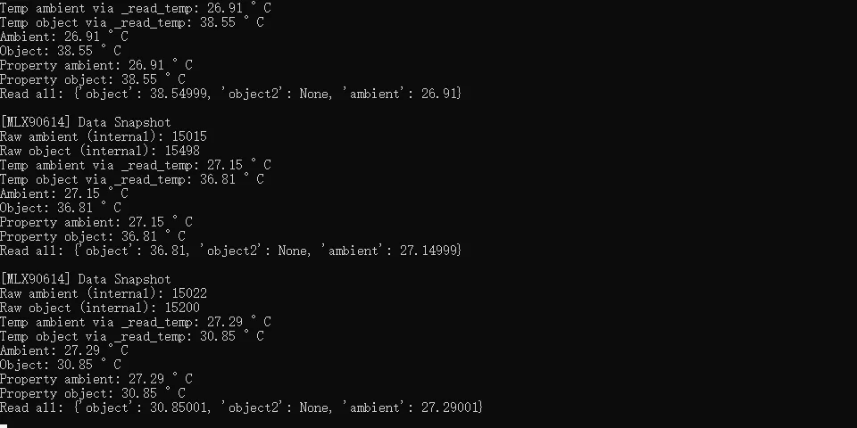
It can be seen that this sensor can realize non-contact measurement of the temperature of the object above it and output the result on the terminal:
IV. Drivers
mlx_90614_driver.zip 13 KB
5. BOM & Recommended Alternative Parts
None.
VI. Revision History
Document Version | Date of Revision | Modifier | Revised Content |
V1.0.0 | 2025.8.31 | Zero Kōkō | The initial version has completed the design. |
V1.1.0 | 2025.12.17 | Zero Kōkō | Optimize the content and format of the document in accordance with the new version of the specifications |
v1.1 | 2025-12-29 | Li Zisheng | Added application experiments and production files |
v1.2 | 2025-12-31 | Xin Ruili | Create an open version of the document based on the internal document version v1.1. |
v1.3 | 2026-03-29 | Xin Ruili | Modified the application experiment section. |
VII. Relevant Materials
7.1 Chip Datasheet
MLX90614 Datasheet.pdf 2.7 MB
7.2 Unique Icons for PCB Silk Screen