Contents
- I. Module Introduction
- II. Introduction to Main Chips
- 2.1 Chip Overview
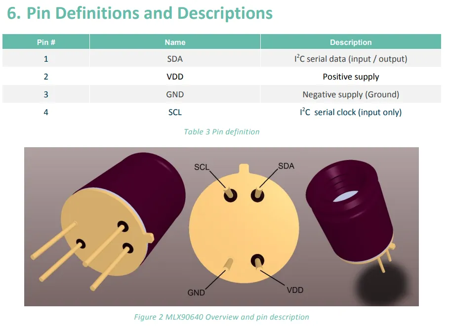
- 2.2 Pin Definition
- 2.3 Functional Block Diagram
- 2.4 Performance Parameters
- 2.5 Reference Circuit
- 2.6 Chip Configuration
- 2.7 Communication Interfaces and Related Protocols
- 2.8 PCB Routing Precautions
- III. Circuit Engineering
- 3.1 Circuit Source Engineering
- 3.2 Module Usage Instructions
- 3.3 Application Experiment
- IV. Drivers
- 5. BOM & Recommended Alternative Parts
- VI. Revision History
- VII. Relevant Materials
- 7.1 Chip Datasheet
- 7.2 Unique Icons for PCB Silk Screen
I. Module Introduction
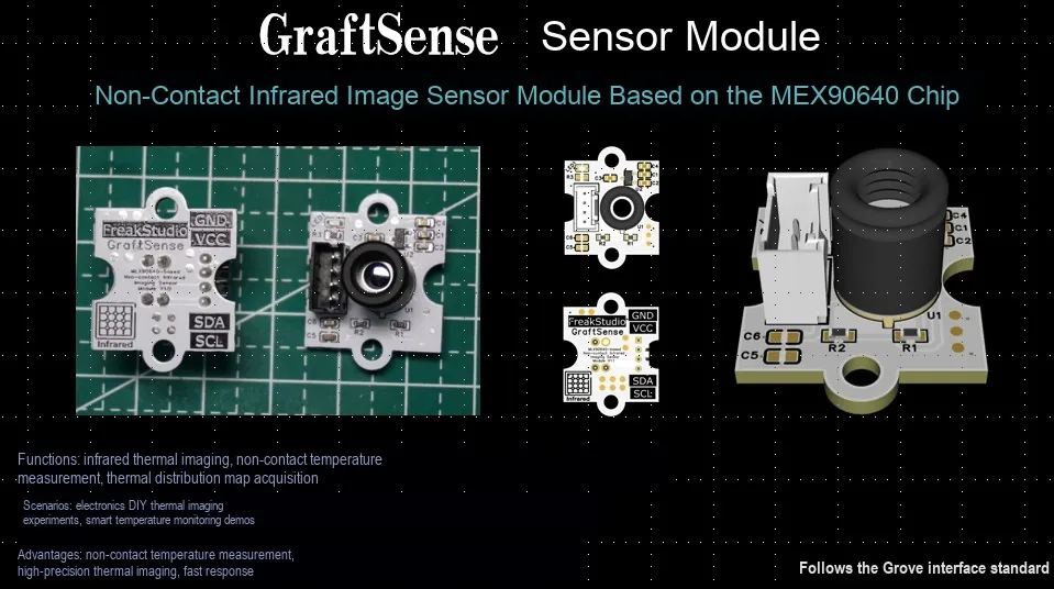
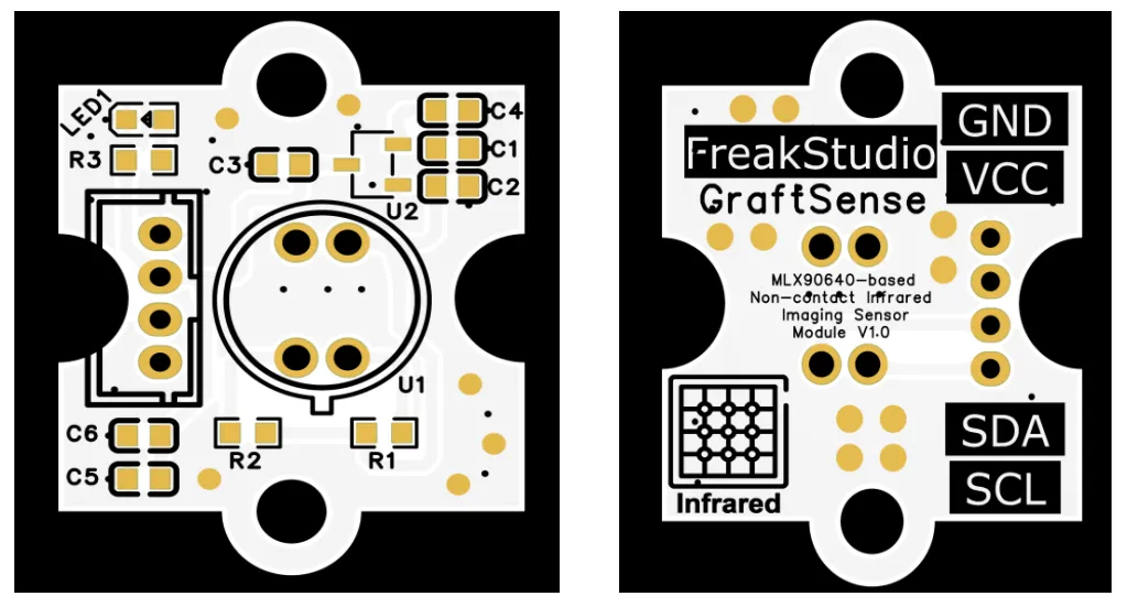
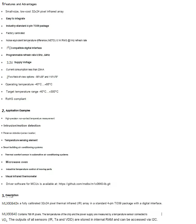
Contactless infrared image sensor module based on MLX90640 chip A thermal infrared array sensor module based on a 32×24 pixel array, adopting TO39 package, featuring a noise equivalent temperature difference performance of 0.1K RMS @ 1Hz refresh rate, and supporting I²C communication.The module operates at a voltage of 3.3V with a current consumption of less than 23mA, features a programmable refresh rate ranging from 0.5Hz to 64Hz, offers two optional fields of view: 55°×35° and 110°×75°, has an operating temperature range of -40°C to 85°C, supports target temperature measurement from -40°C to + 300°C, and complies with the RoHS directive. It is suitable for scenarios such as non-contact temperature detection and thermal imaging analysis, providing accurate infrared image sensing solutions for industrial monitoring, smart home and other fields.
II. Introduction to Main Chips
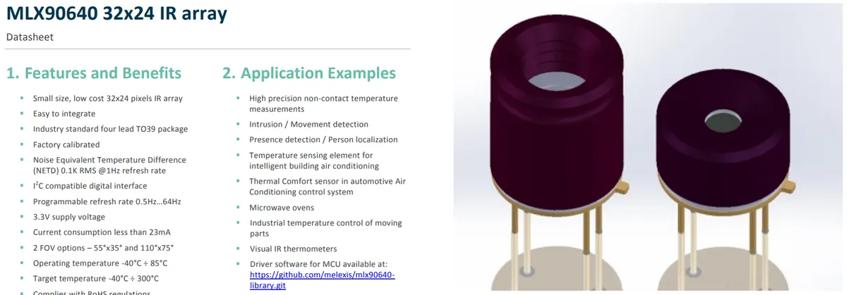
MLX90640 is an industrial-grade calibrated thermal infrared array sensor launched by Melexis, which features a total of 768 pixels in a 32×24 resolution, a wide temperature measurement range from -40°C to 300°C, a typical temperature measurement accuracy of approximately ±1°C, a noise equivalent temperature difference of only 0.1K at a 1Hz refresh rate, and optional field-of-view angles of 55°×35° and 110°×75° to adapt to different ranging scenarios, enabling continuous operation without additional calibration.It is equipped with an I²C-compatible digital interface supporting a maximum communication rate of 1MHz, and incorporates a built-in ambient temperature sensor and voltage detection ADC, which enables it to read a variety of real-time data via the interface. It can be easily integrated into various embedded systems, and is widely used in non-contact thermal imaging and temperature measurement scenarios such as industrial temperature measurement, intelligent buildings, and security monitoring.
2.1 Chip Overview
2.2 Pin Definition
2.3 Functional Block Diagram
None.
2.4 Performance Parameters
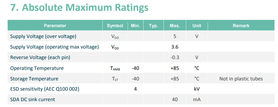
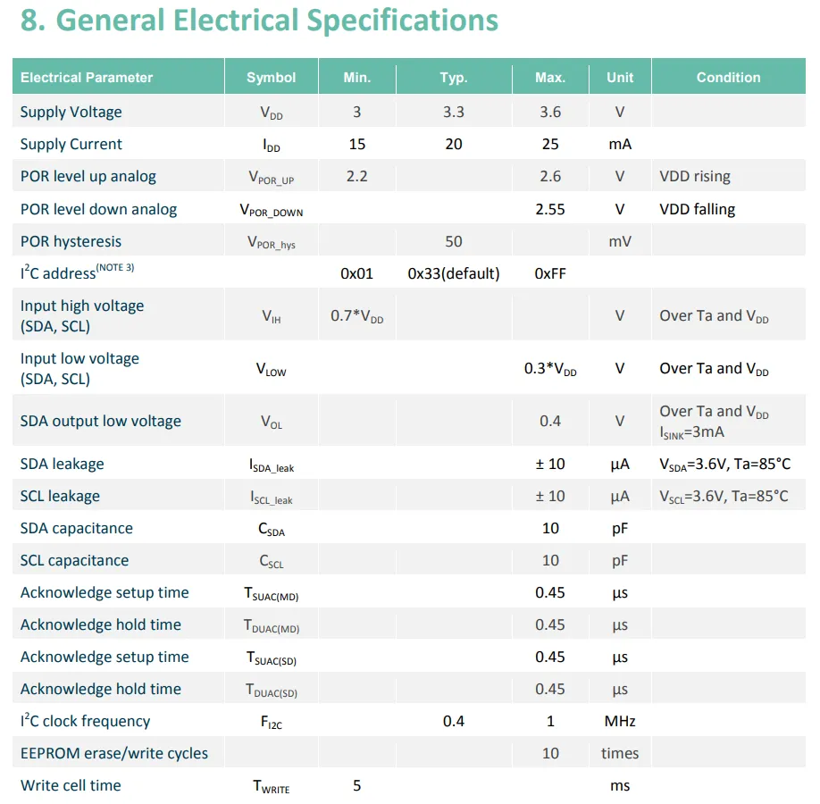
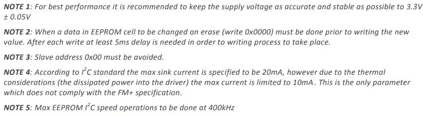
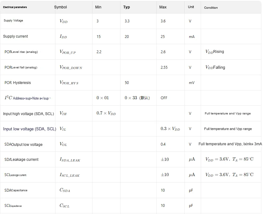
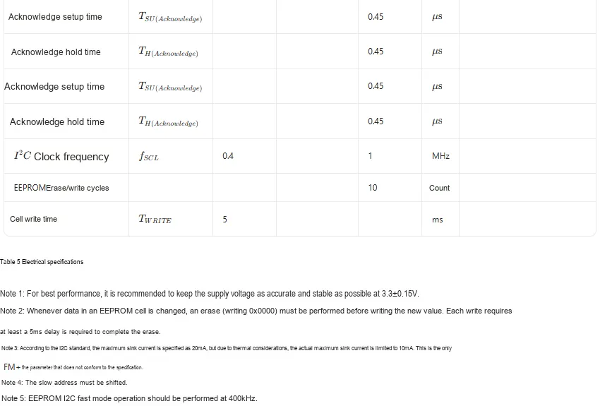
Some of the data in the above table are shown as follows:
- Supply Voltage: 3~3.6V, typically 3.3V, which is the power supply range for normal operation of the chip.
- Supply Current: 15~25mA, typically 20mA, which reflects the power consumption level of the chip.
- POR level: 2.2~2.6V when rising, ≤2.55V when falling, with 50mV hysteresis, enabling power supply abnormality monitoring.
I²Caddress: Default is 0×33, can be set to 0×01 or disabled, used for device addressing.- Input level: High level ≥ 0.7×VDD, low level ≤ 0.3×VDD, to ensure valid identification of I²C signals.
- SDA output low voltage: ≤0.4V (I<sub>sink</sub>≤3mA), ensuring the low-level output capability.
- Leakage Current: For SDA and SCL, the maximum value is ±10μA, with low quiescent current.
- Pin capacitance: For SDA and SCL, the maximum value is 10pF, which affects the frequency characteristics of I²C communication.
2.5 Reference Circuit
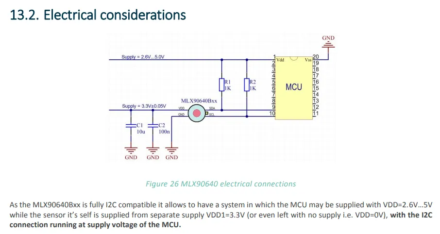
In this MLX90640 reference circuit, the sensor is powered by 3.3V, with 10μF and 100nF capacitors to filter power supply ripple for stable power delivery; its SDA and SCL pins are pulled up via 1kΩ resistors and then connected to the MCU, which not only maintains the idle level of the I2C bus but also adapts to the level difference between devices; meanwhile, the sensor, capacitors and the MCU share a common ground to eliminate potential difference, collectively achieving stable power supply and reliable I2C communication.
2.6 Chip Configuration
None.
2.7 Communication Interfaces and Related Protocols
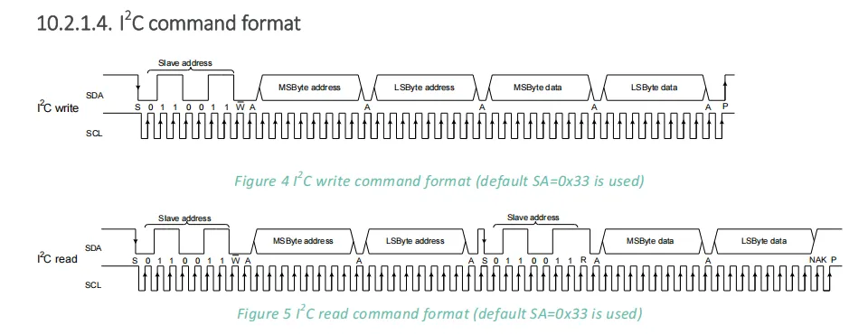
The MLX90640 adopts I2C communication, with a default slave address of 0x33.
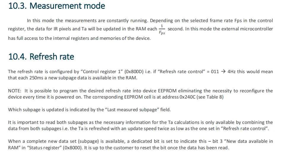
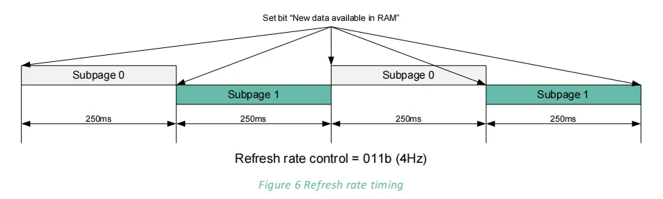
MLX90640 allows users to configure its measurement mode and refresh rate, a brief description of which is provided below:
- Measurement Mode: The device operates continuously, and based on the frame rate set in the control register
Fps, updates the infrared pixels and ambient temperature (Ta) data inRAMevery 1 second at the rate ofFps, and the host can access its internal registers/memory. - Refresh rate: Configured via Control Register 1 (
0x800D)(e. g., "011" corresponds to 4Hz, updating subpage data inRAMevery 250ms); the configuration can also be written toEEPROM(0x240C) for power-off retention. Calculation ofTa(Taupdate rate is 1/2 of the refresh rate) requires reading data from two subpages. The "new data available" bit in the Status Register (0x8000) indicates subpage update, and this bit must be reset after reading.
2.8 PCB Routing Precautions
None.
III. Circuit Engineering
3.1 Circuit Source Engineering
To obtain the source code of the circuit, please follow the official account [Freak Embedded]
3.2 Module Usage Instructions
SCH_Schematic1_MLX90640-Based Non-Contact Infrared Image Sensor Module_v1.0_2025-11-11.pdf 2.0 MB
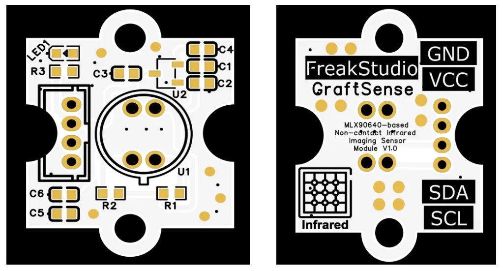
This module provides an I2C communication interface: it supports standard I2C communication rate, with a default I2C address of 0x33, is compatible with 3.3V logic level, and can stably transmit thermal infrared array data of 32×24 pixels (including target temperature information ranging from -40°C to + 300°C). It can also transmit configuration commands such as programmable refresh rate (0.5Hz to 64Hz), and is suitable for scenarios including non-contact temperature detection, thermal imaging analysis, and industrial equipment monitoring, providing accurate thermal data interaction capabilities for infrared sensing applications.
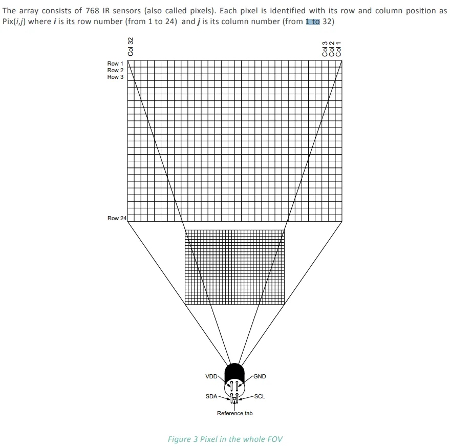
As we can see, each infrared detection point (pixel) on the module is denoted by Pix (i, j). When retrieving data, we only need to use "row number i (1-24) + column number j (1-32)" to accurately map to a specific detection position on the module.
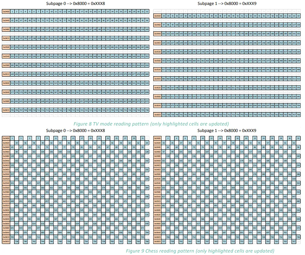
Meanwhile, note that the module splits and stores the data of 768 sensors into two data subpages: " Subpage 0 (corresponding to address 0x8000= 0xXXX8)" and " Subpage 1 (corresponding to address 0x8000= 0xXXX9)"; regardless of the mode, each time a read is triggered, only the data of the highlighted cells (corresponding to sensors) in the diagram will be updated in real time, while the non-highlighted cells will retain their previous values:
TVMode:- The highlighted area refers to the "segmented region of consecutive rows"(for example, the sensors in certain rows will be updated in batches);
- Usage scenario: Suitable for scenarios requiring fast update of infrared data in continuous regions (e. g., detecting continuous movement of infrared targets).
ChessMode:- The highlighted area represents the "checkerboard-patterned discrete points"(sensors are updated discretely);
- Usage scenario: Suitable for scenarios that require balancing multi-region sampling while reducing the number of sensors updated in a single operation (e. g., lowering module power consumption, controlling the volume of data transmitted in a single batch).
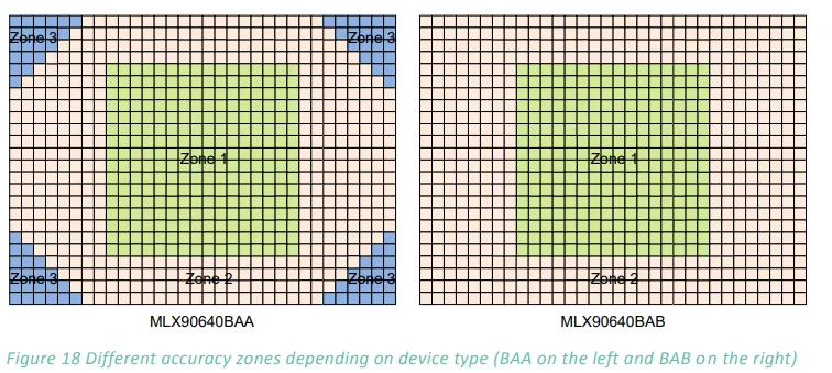
Furthermore, for different models of the MLX90640 probe, their accuracy partitioning also varies:
MLX90640BAAModel:- There are 3 accuracy levels: the large middle area
Zone1(green zone) is the area with the highest accuracy, the small area below, namelyZone2, has the second highest accuracy, and the four-corner areas, namelyZone3(blue zone), have the relatively lowest accuracy; - Usage Notes: If your test target requires high-precision data, align the target as close to the center of the
Zone1as possible, and avoid placing it in the cornerZone3area.
- There are 3 accuracy levels: the large middle area
MLX90640BABModel:- Simplified precision zoning: only the middle
Zone1(green zone, high precision) and the lowerZone2, without the low-precision cornerZone3exclusive toBAAmodels; - Usage Notes: It features a wider high-precision coverage range, and can maintain good accuracy even when the detection target is close to the edge of the module (excluding the lower
Zone2), making it suitable for scenarios that require high detection accuracy in edge areas.
- Simplified precision zoning: only the middle
Briefly, when selecting a model: if you need accuracy to cover corner areas, prioritize BAB; when using the module, no matter which model it is, try to align the core detection target with its respective Zone1 area to obtain optimal data.
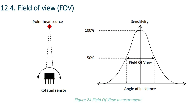
Field of view (FOV) refers to the angular range within which the sensor maintains effective detection sensitivity — in the curve on the right, the angular interval where the incident angle of the heat source corresponds to a sensor sensitivity of ≥50% is defined as FOV; when directly facing the sensor (incident angle = 0°), the sensitivity reaches 100%, delivering the optimal detection performance.
When arranging the detection target, try to align the heat source with the directly front of the sensor (incident angle of 0°), as this yields the highest sensitivity and the most accurate data; if heat sources at different angles need to be detected, be sure that the target stays within the angle range of the FOV to avoid detection failure caused by out-of-limit angles.
3.3 Application Experiment
Here, we use the GraftPort-RP2040 development board for testing, and the non-contact infrared image sensor module based on the MLX90640 chip uses the I2C interface to communicate with the main controller.
Here, we first use the HY2.0-4P cable to connect the module to the GraftPort-RP2040 development board's I2C0 interface:
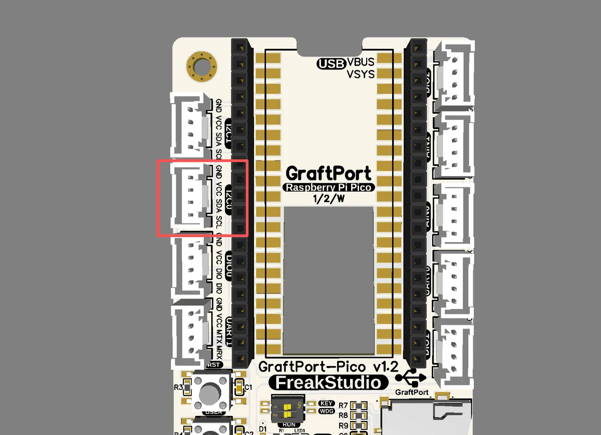
The module connections are shown in the following table:
Development Board Pins | Module Pins | Description |
Pin 4 |
|
|
Pin 5 |
|
|
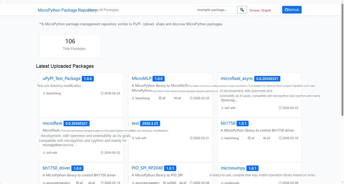
Here, we need to search for relevant driver packages on uPyPI: https://upypi.net/zh/
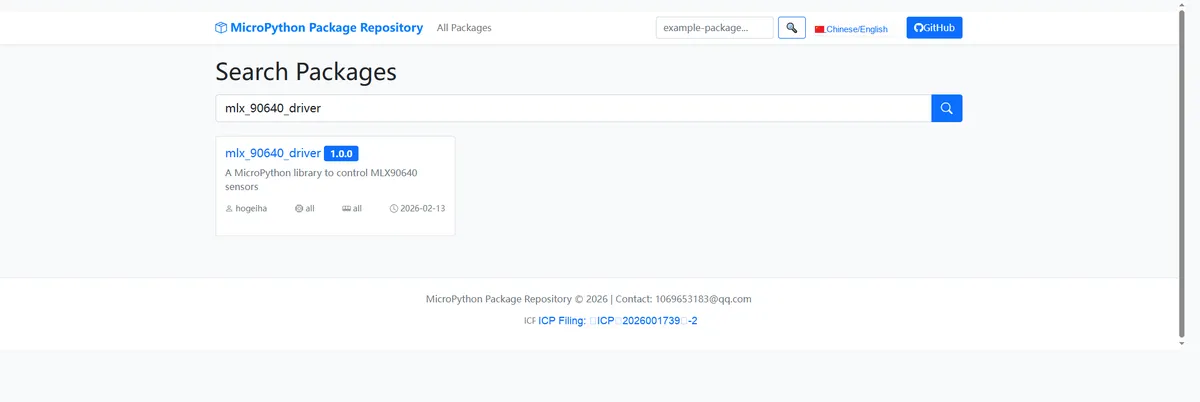
Enter mlx_90640_driver to search, and the following will be displayed:
Click to copy the local installation command:
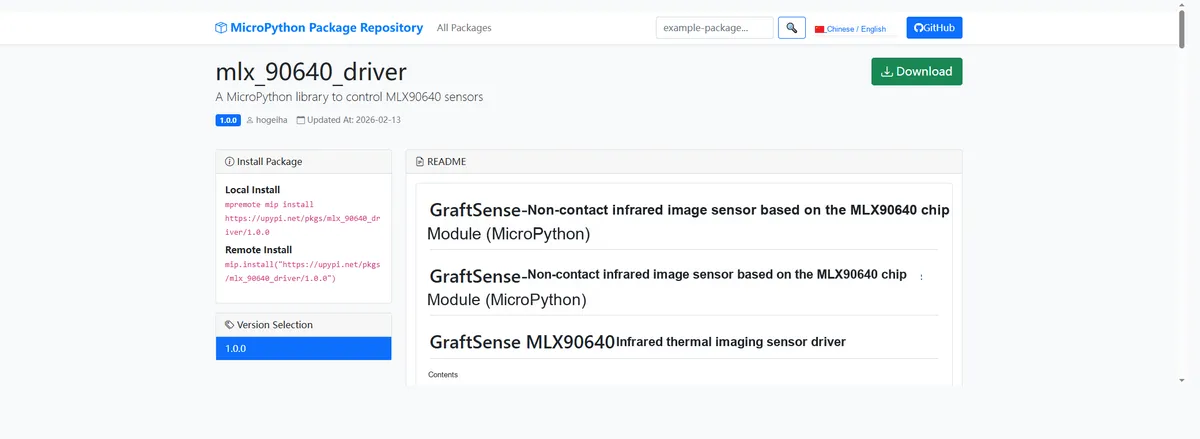
Here, we can use the mip tool to import module driver library code. Below are the usage commands for the mpremote tool:
mpremote mip install github:FreakStudioCN/GraftSense-Drivers-MicroPython/sensors/mlx90640_driverImport the contactless infrared image sensor module based on the MLX90640 chip - MicroPython driver code, then copy the following main.py code into our project:
# Python env   : MicroPython v1.23.0
# -*- coding: utf-8 -*-
# @Time    : 2025/8/27 11:50 AM
# @Author  : 缪贵成
# @File    : main.py
# @Description : mlx90614 dual-zone temperature sensor test file

# ======================================== Import Modules =========================================

import time
from machine import I2C, Pin
from mlx90614 import MLX90614, MLX90615

# ======================================== Global Variables =============================================

mlx61xaddr=None

# ======================================== Functions =============================================

def test_sensor_realtime(sensor, name="Sensor", interval=1.0):
    """

    Display sensor temperature data in real time, covering all function tests.
    Args:
        sensor: MLX90614 or MLX90615 sensor instance
        name: Sensor name, used for output labeling
        interval: Data refresh interval, in seconds

    Notes:
        The tests cover internal methods, public methods, property access, and one-shot read functionality
        Dual-zone sensors additionally display the second object temperature channel
        Internal method tests may vary depending on the sensor model

    ==========================================

    Realtime display of sensor temperature data, covering all functional tests.

    Args:
        sensor: Instance of MLX90614 or MLX90615 sensor
        name: Sensor name for output identification
        interval: Data refresh interval in seconds

    Notes:
        Tests include internal methods, public methods, property access and one-time read function
        Dual-zone sensors will additionally display the second object temperature data
        Internal method tests may vary by sensor model
    """
    print("\n=== Realtime testing {} ===".format(name))
    print("Dual zone:", sensor.dual_zone)  # Output whether the sensor is dual-zone
    print("Press Ctrl+C to stop")  # Prompt the user that Ctrl+C can be used to stop the test

    try:
        while True:
            # ================= Internal Method Tests =================
            try:
                # Read the raw register value (16-bit)
                raw_ambient = sensor._read16(sensor._REGISTER_TA)
                raw_object = sensor._read16(sensor._REGISTER_TOBJ1)

                # Convert the raw register value to degrees Celsius
                temp_ambient_internal = sensor._read_temp(sensor._REGISTER_TA)
                temp_object_internal = sensor._read_temp(sensor._REGISTER_TOBJ1)
            except Exception as e:
                print("[Internal] Error:", e)
                raw_ambient = raw_object = temp_ambient_internal = temp_object_internal = None

            # ================= Public Method Tests =================
            ambient = sensor.read_ambient()  # Read ambient temperature
            obj = sensor.read_object()       # Read object temperature
            # For dual-zone sensors, read the second object temperature; otherwise None
            obj2 = sensor.read_object2() if sensor.dual_zone else None

            # ================= Property Access Tests =================
            ambient_prop = sensor.ambient
            obj_prop = sensor.object
            obj2_prop = sensor.object2 if sensor.dual_zone else None

            # ================= One-Shot Read Function Tests =================
            try:
                all_data = sensor.read()  # Read all data at once (returns a dict)
            except Exception as e:
                all_data = None

            # ================= Data Output =================
            print("\n[{}] Data Snapshot".format(name))
            print("Raw ambient (internal):", raw_ambient)
            print("Raw object (internal):", raw_object)
            if temp_ambient_internal is not None:
                print("Temp ambient via _read_temp: {:.2f} °C".format(temp_ambient_internal))
            if temp_object_internal is not None:
                print("Temp object via _read_temp: {:.2f} °C".format(temp_object_internal))
            print("Ambient: {:.2f} °C".format(ambient))
            print("Object: {:.2f} °C".format(obj))
            if sensor.dual_zone:
                print("Object2: {:.2f} °C".format(obj2))
            print("Property ambient: {:.2f} °C".format(ambient_prop))
            print("Property object: {:.2f} °C".format(obj_prop))
            if sensor.dual_zone:
                print("Property object2: {:.2f} °C".format(obj2_prop))
            print("Read all:", all_data)

            # Wait for a while before refreshing
            time.sleep(interval)

    except KeyboardInterrupt:
        # Exit the loop when the user presses Ctrl+C
        print("\nRealtime testing stopped")

# ======================================== Custom Classes =============================================

# ======================================== Initialization configuration ===========================================

# Hardware power-on delay to ensure the sensor has finished initializing
time.sleep(3)
print("FreakStudio: MLX90614 test start ")
# ================= I2C Initialization =================
i2c = I2C(0, scl=5, sda=4, freq=100000)
# Start scanning for devices on the I2C bus and return a list of slave addresses
devices_list: list[int] = i2c.scan()
print('START I2C SCANNER')
# If the devices list is empty, no device is connected to the I2C bus
if len(devices_list) == 0:
    # If not empty, print the slave device addresses
    print("No i2c device !")
else:
    print('i2c devices found:', len(devices_list))
for device in devices_list:
    if 0x5A <= device <= 0x5D:
        print("I2c hexadecimal address:", hex(device))
        mlx61xaddr = device

# Initialize MLX90614
sensor14 = MLX90614(i2c, mlx61xaddr)
print("[MLX90614] Sensor initialized.")
# Initialize MLX90615
sensor15 = MLX90615(i2c, mlx61xaddr)
print("[MLX90615] Sensor initialized.")

# ======================================== Main Program ==============================================

# ================= MLX90614 Test =================
print("\n--- Starting MLX90614 Realtime Test ---")
test_sensor_realtime(sensor14, "MLX90614", interval=1.0)

# ================= MLX90615 Test =================
print("\n--- Starting MLX90615 Realtime Test ---")
test_sensor_realtime(sensor15, "MLX90615", interval=1.0)
To flash the code, open a terminal and use the mpremote tool to connect to the main controller; the output is as follows:
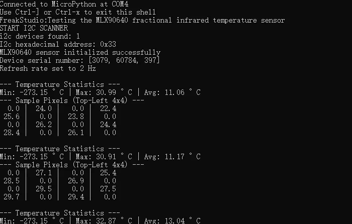
It can be seen that as we wave our hand directly above the sensor module, the terminal outputs the temperature pixel values of the 4×4 area, and meanwhile counts the minimum, maximum and average values of the current temperature: -
IV. Drivers
mlx90640_driver.zip 25 KB
5. BOM & Recommended Alternative Parts
None.
VI. Revision History
Document Version | Date of Revision | Modifier | Revised Content |
v1.0 | 2025-11-11 | Zero Kōkō | Initialize the document |
v1.1 | 2025-12-29 | Li Zisheng | Added application experiments and production files |
v1.2 | 2025-12-31 | Xin Ruili | Create an open version of the document based on the internal document version v1.1. |
v1.3 | 2026-03-29 | Xin Ruili | Modified the application experiment section |
VII. Relevant Materials
7.1 Chip Datasheet
MLX90640 Manual.pdf 2.1 MB
7.2 Unique Icons for PCB Silk Screen