Contents
- I. Module Introduction
- II. Introduction to Main Chips
- 2.1 Chip Overview
- 2.2 Pin Definition
- 2.3 Functional Block Diagram
- 2.4 Performance Parameters
- 2.5 Reference Circuit
- 2.6 Chip Configuration
- 2.7 Communication Interfaces and Related Protocols
- 2.8 PCB Routing Precautions
- III. Instructions for Circuit Engineering and Module Usage
- 3.1 Circuit Source Engineering
- 3.2 Module Usage Instructions
- 3.3 Application Experiment
- IV. Drivers
- 5. BOM & Recommended Alternative Parts
- VI. Revision History
- VII. Relevant Materials
- 7.1 Chip Datasheet
- 7.2 Unique Icons for PCB Silk Screen
I. Module Introduction
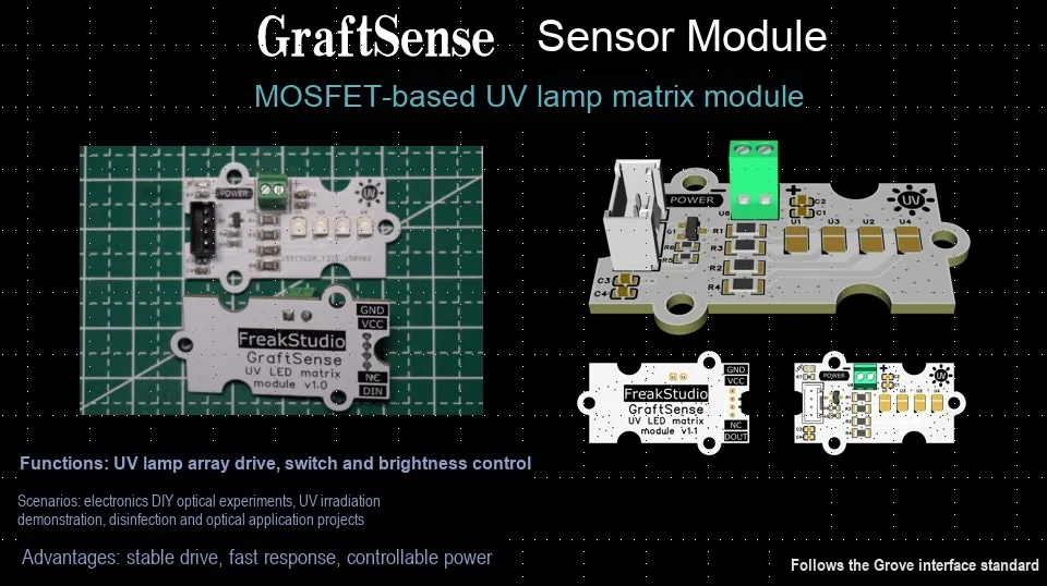
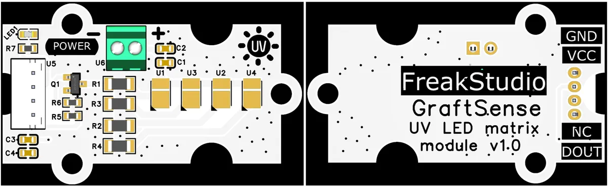
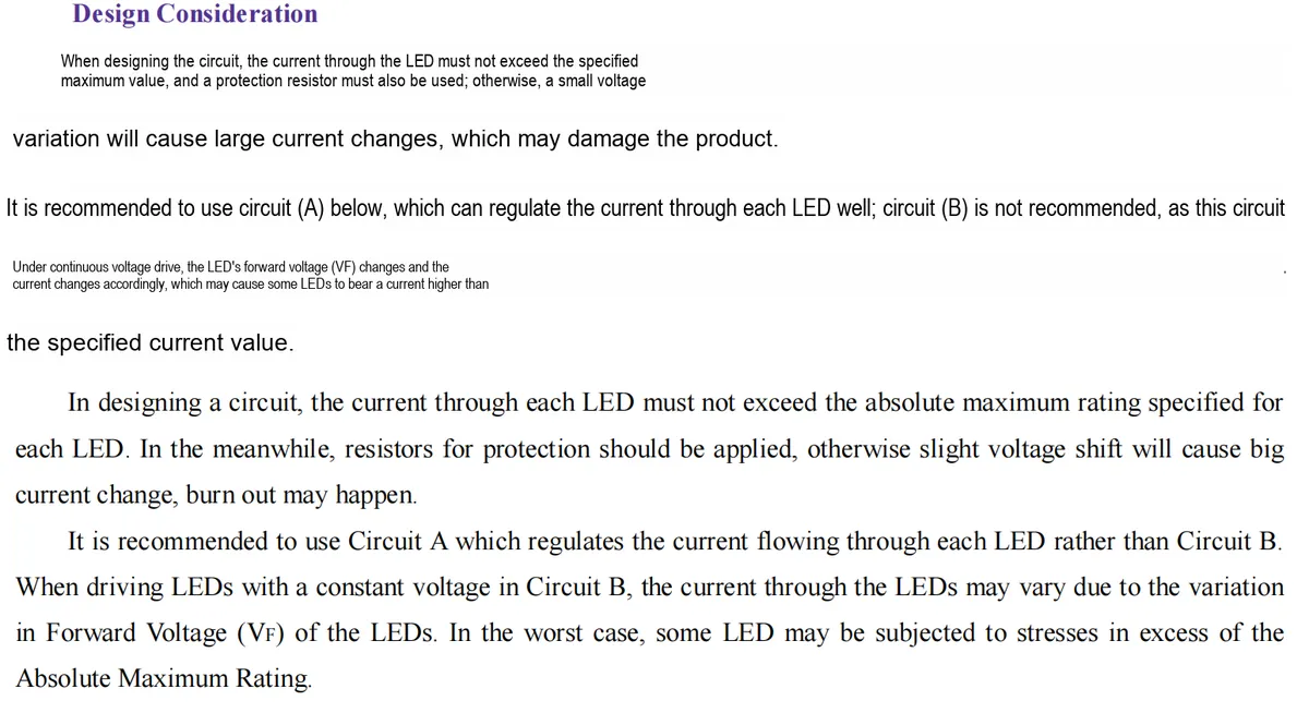
MOSFET-based UV Ultraviolet Lamp Matrix Module with its core adopting AO3400 MOS FET to control 4 pieces of 365nm ultraviolet LED in 3030 package (parallel array). The power terminal is regulated via a filter capacitor, and the MCU can control the on/off of the DOUT interface to switch the lamp array on and off through the MOS FET;Each LED is connected in series with a 5.6Ω current-limiting resistor (matching the requirements of 3.4V forward voltage and 0.3A operating current for LED under 5V power supply). LEDs are connected in parallel rather than in series (to avoid the requirement for high power supply voltage). The AO3400 MOS tube features low on-resistance and low power consumption. The module is also equipped with a power indicator, enabling convenient on-off control of the ultraviolet lamp array, and is suitable for scenarios such as ultraviolet assistance for plant growth.
II. Introduction to Main Chips
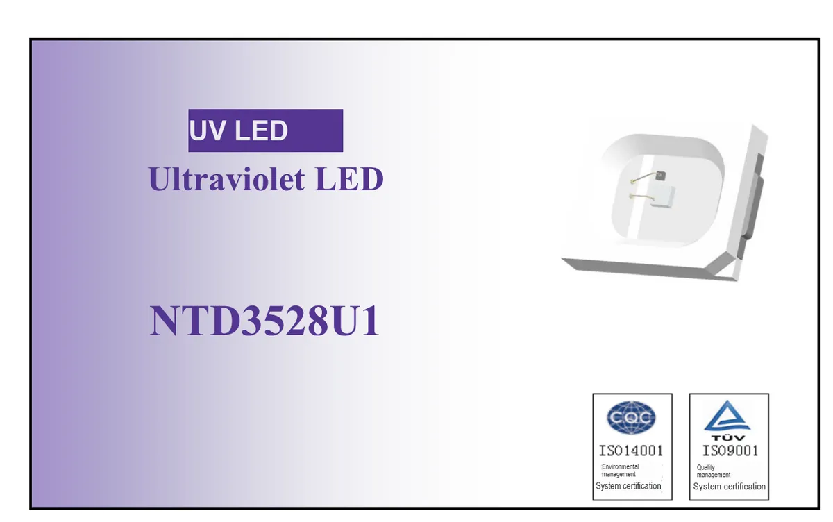
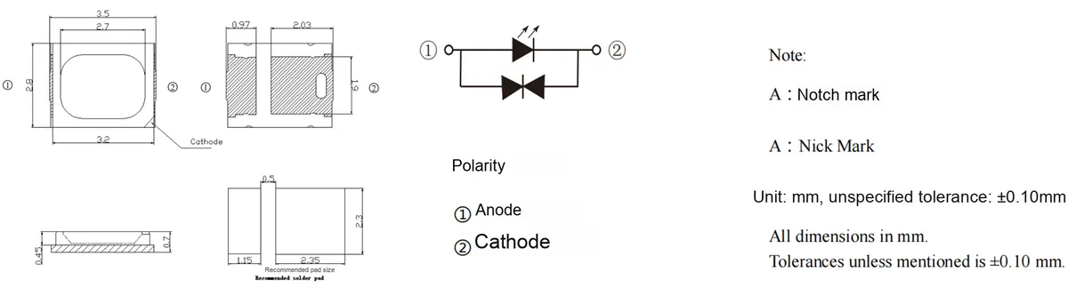
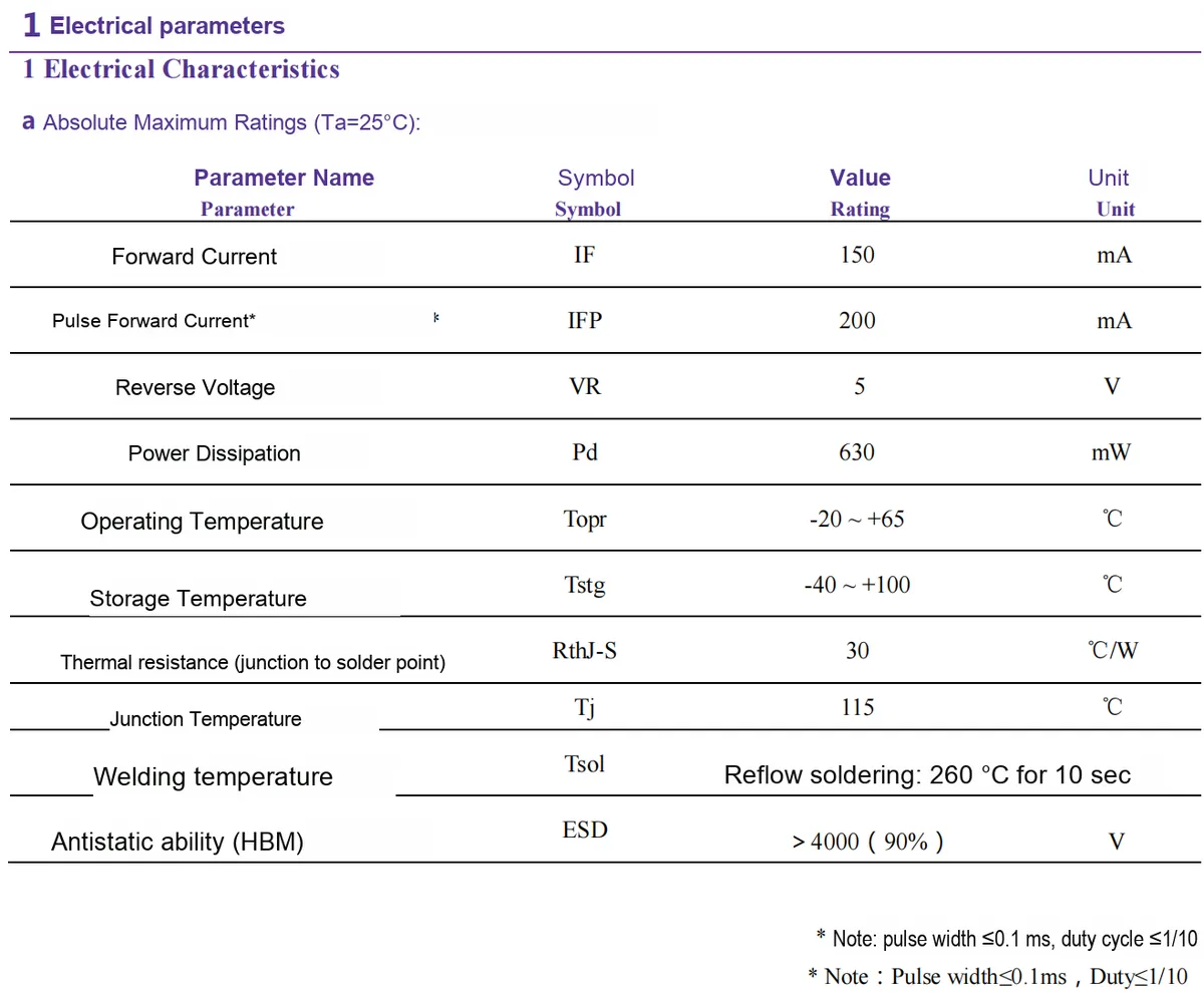
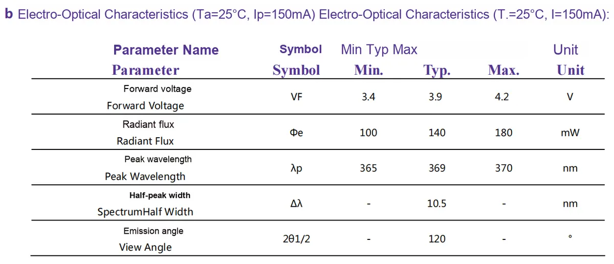
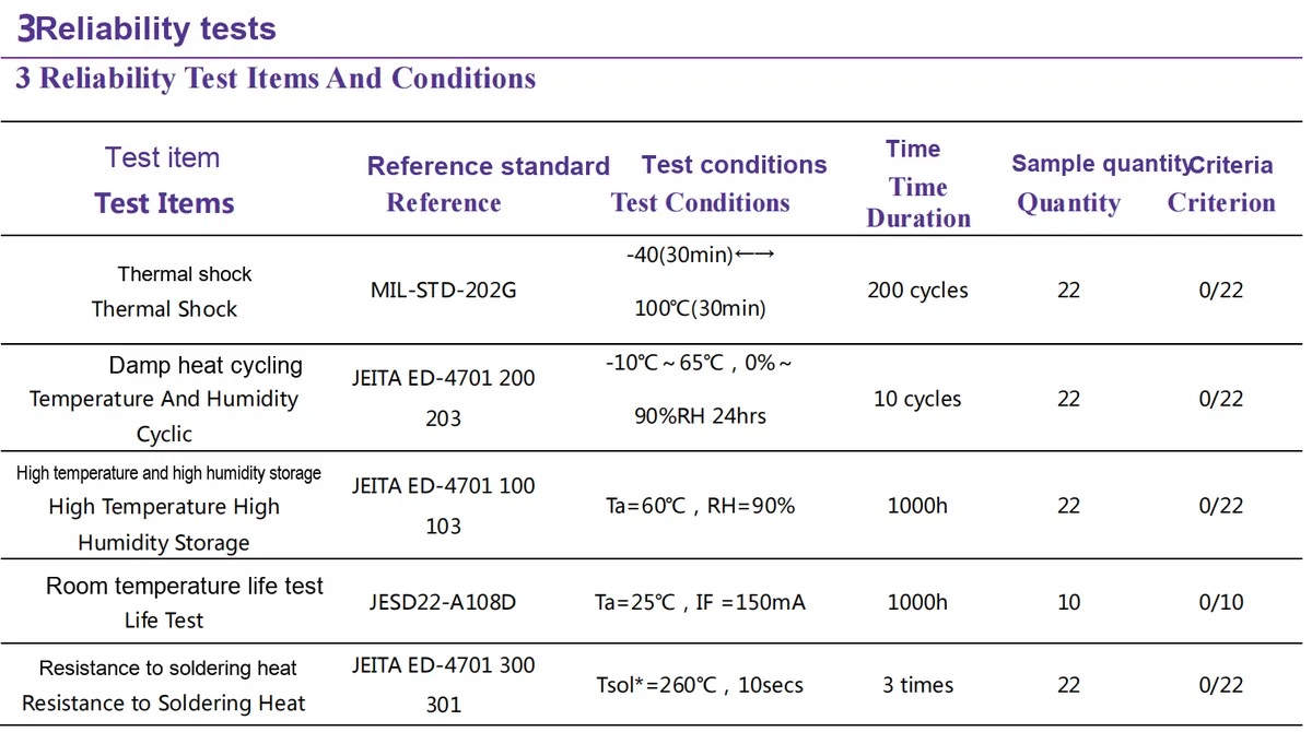
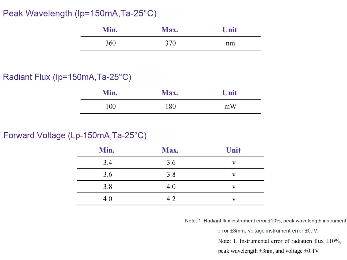
The core component of this module is NTD3528U1, which is an ultraviolet LED with a wavelength of 360-370nm (typical 369nm), adopts a 3.5×2.8mm package, supports lead-free reflow soldering, complies with the ROHS directive and has passed the ISO14001/9001 system certification;Its forward operating current is 150mA (at a forward voltage of 3.4-4.2V), the radiant flux reaches 100-180mW, and the light output angle is 120°. Featuring high luminous intensity, low power consumption and long service life, it has passed reliability tests such as thermal shock, and is suitable for applications including insect trapping, anti-counterfeiting identification and nail art.
2.1 Chip Overview
2.2 Pin Definition
2.3 Functional Block Diagram
None.
2.4 Performance Parameters
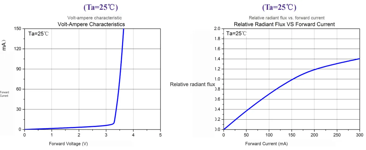
These two diagrams illustrate NTD3528U1 ultraviolet LED characteristics at an ambient temperature of 25°C:
- The left figure shows the volt-ampere characteristic curve, which presents the relationship between forward voltage and forward current. It can be seen that when the forward voltage rises to about 3V, the forward current increases rapidly, reflecting the turn-on characteristic of
LED; - The figure on the right shows the relationship curve between relative radiant flux and forward current. It can be seen that as the forward current increases, the relative radiant flux rises gradually, indicating that increasing the operating current can enhance the ultraviolet output intensity of this
LED.
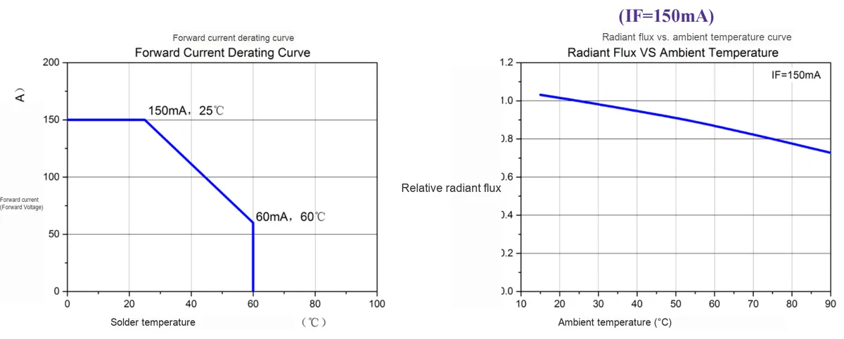
These two diagrams illustrate NTD3528U1 ultraviolet LED temperature-dependent characteristics:
- The left figure shows the derating curve of forward current: the rated forward current is 150mA at 25°C, while when the solder joint temperature rises to 60°C, the forward current needs to be derated to 60mA, which reflects that the operating current shall be reduced as the temperature increases to ensure device reliability;
- The figure on the right shows the relationship curve between radiant flux and ambient temperature. Under the condition of a forward current of 150mA, the higher the ambient temperature, the lower the relative radiant flux, which indicates that a temperature rise will weaken the ultraviolet output intensity of this
LED.
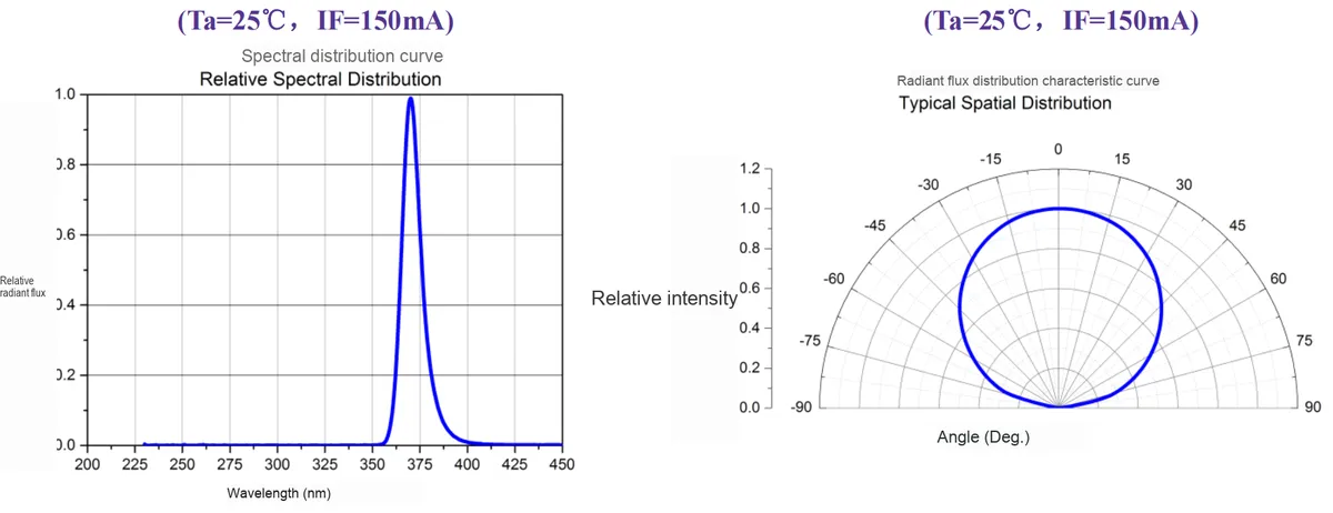
These two diagrams illustrate the radiation characteristics of NTD3528U1 ultraviolet LED under the conditions of 25°C and a forward current of 150mA:
- The left figure shows the spectral distribution curve, from which it can be seen that the relative radiant flux is concentrated in the wavelength range of 360-370 nm, corresponding to its nominal ultraviolet band;
- The figure on the right shows the spatial distribution curve of radiant flux, which presents a wide-angle annular distribution, reflecting that this
LEDhas a light output angle of approximately 120°, with a relatively wide ultraviolet light emission range.
2.5 Reference Circuit
None.
2.6 Chip Configuration
None.
2.7 Communication Interfaces and Related Protocols
None.
2.8 PCB Routing Precautions
III. Instructions for Circuit Engineering and Module Usage
3.1 Circuit Source Engineering
To obtain the source code of the circuit, please follow the official account [Freak Embedded]
3.2 Module Usage Instructions
The schematic diagram of this module is shown below:
SCH_MOSFET-Based UV Lamp Matrix Module_v1.0_2025-11-25.pdf 2.0 MB
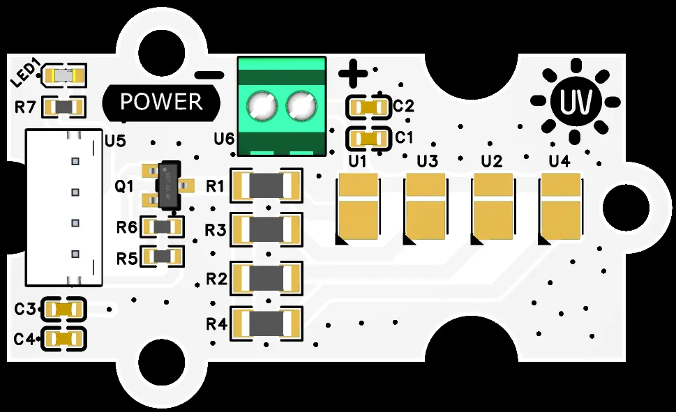
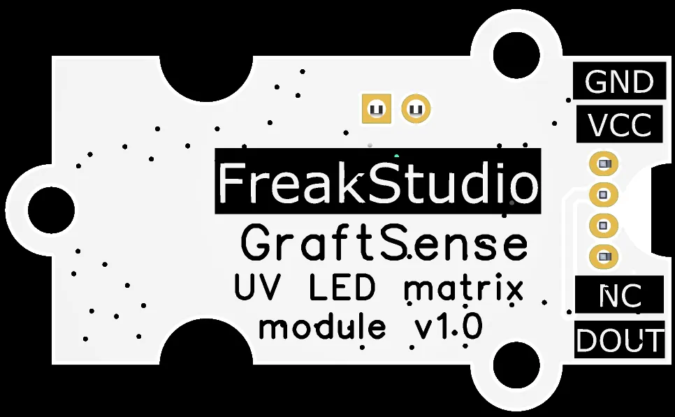
This module provides a digital input interface DOUT 's MCU ' s GPIO to receive the high and low level signals output by the MCU, so as to control the on/off status of the ultraviolet lamp array.
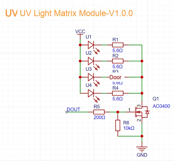
The core logic of the schematic diagram for this UV lamp matrix module is as follows: U1 - U4 are 4 ultraviolet LEDs, each LED is connected in series with a 5.6Ω R1 - R4 as a current-limiting resistor to match the supply voltage and the LED operating current;MOS transistor Q1 (AO3400) serves as the core switch, its gate is connected to the R5 (200Ω) to the DOUT interface, and pulled down to ground via R6 (10kΩ)(to stabilize the gate level during idle state):
- When
the MCUoutputs a high level viaDOUT,Q1turns on, and the LED array is connected betweenVCCand ground to light up; - When
DOUToutputs a low level,Q1is cut off, the lamp array is powered off and goes out, thereby realizing the digital switch control of the ultraviolet lamp array byMCU.
3.3 Application Experiment
Here, we use the GraftPort-RP2040 development board for testing, and connect the MOSFET-based UV ultraviolet lamp matrix module to communicate with the main controller via the AIN interface.
Here, we first use the HY2.0-4P connection cable to connect the module to the GraftPort-RP2040 development board's AIN0 interface:
We use the LM2596S adjustable power supply module to supply power to the MOSFET-based UV ultraviolet lamp matrix module via a 5V external power source
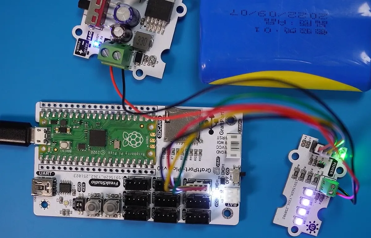
The module connections are shown in the following table:
Development Board Pins | Module Pins | Description |
Pin 6 |
| The pin on the MCU that generates PWM waveform output or high/low level output |
Pin 7 |
| - |
- | terminal | LM2596S Adjustable Power Supply Module Power Supply |
Here, we need to search for relevant driver packages on uPyPI: https://upypi.net/zh/

Enter uv_matrix to search, and the following will be displayed:

Click to copy the local installation command:
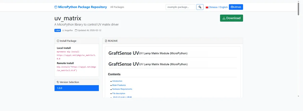
Here, we can use the mip tool to import module driver library code. Below are the usage commands for the mpremote tool:
mpremote mip install github:FreakStudioCN/GraftSense-Drivers-MicroPython/lighting/uv_matrixImport the MOSFET-based UV lamp matrix module - MicroPython driver code, then copy the following main.py code into our project:
# MicroPython v1.23.0
# -*- coding: utf-8 -*-
# @Time    : 2025/8/26 10:45 AM
# @Author  : 缪贵成
# @File    : main.py
# @Description : Test file for the UV ultraviolet light matrix module driver. It is recommended not to keep it fully on for long periods. If you need full brightness, replace the resistors, otherwise the board will heat up quickly and cause unexpected consequences

# ======================================== Import Modules =========================================

import time
from uv_matrix import UVMatrix

# ======================================== Global Variables ============================================

# ======================================== Functions ============================================

# ======================================== Custom Classes ============================================

# ======================================== Initialization configuration ===========================================

time.sleep(3)
print("Freak_studio:UV matrix test")
# Initialize UVMatrix, assuming control pin 26 and PWM frequency 1000Hz
uv = UVMatrix(pin=26, pwm_freq=1000)

# ========================================  Main Program  ===========================================

print("status:", uv.get_state())

# Turn on UVMatrix (full brightness)
uv.on()
print("UV is light full:", uv.get_state())
time.sleep(2)

# Half-brightness adjustment
uv.set_brightness(512)
print("UV PWM duty=512")
time.sleep(2)

# Turn off UVMatrix
uv.off()
print("UV status:", uv.get_state())
time.sleep(2)

# Test the toggle state switch
uv.toggle()
print("UV toggle:", uv.get_state())
time.sleep(2)
uv.toggle()
print("UV toggle:", uv.get_state())
To flash the code, open a terminal and use the mpremote tool to connect to the main controller; the output is as follows:
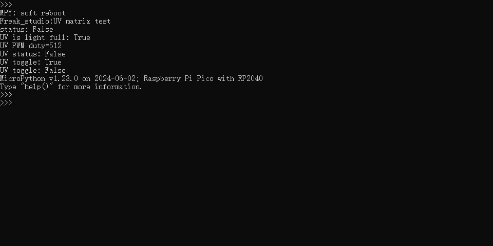
It can be seen that the ultraviolet lamps on the module operate at different brightness levels in accordance with the set program.
IV. Drivers
uv_matrix.zip 10 KB
5. BOM & Recommended Alternative Parts
None.
VI. Revision History
Document Version | Date of Revision | Modifier | Revised Content |
v1.0 | 2025-11-25 | Li Zisheng | Initialize the document The BOM sheet has not been finally checked, the driver has not been re-verified, and the 3.3 application experiment Not yet specified. |
v1.1 | 2025-12-29 | Li Zisheng | Added application experiments and production files |
v1.2 | 2025-12-31 | Xin Ruili | Create an open version of the document based on the internal document version v1.1. |
v1.3 | 2026-03-29 | Xin Ruili | Modified the application experiment section |
VII. Relevant Materials
7.1 Chip Datasheet
Datasheet.pdf 1.3 MB
7.2 Unique Icons for PCB Silk Screen