Contents
- I. Module Introduction
- II. Introduction to Main Chips
- 2.1 Chip Overview
- 2.2 Pin Definition
- 2.3 Functional Block Diagram
- 2.4 Performance Parameters
- 2.5 Reference Circuit
- 2.6 Chip Configuration
- 2.7 Communication Interfaces and Related Protocols
- 2.8 PCB Routing Precautions
- III. Instructions for Circuit Engineering and Module Usage
- 3.1 Circuit Source Engineering
- 3.2 Module Usage Instructions
- 3.3 Application Experiment
- IV. Drivers
- 5. BOM & Recommended Alternative Parts
- VI. Revision History
- VII. Relevant Materials
- 7.1 Chip Datasheet
- 7.2 Unique Icons for PCB Silk Screen
I. Module Introduction
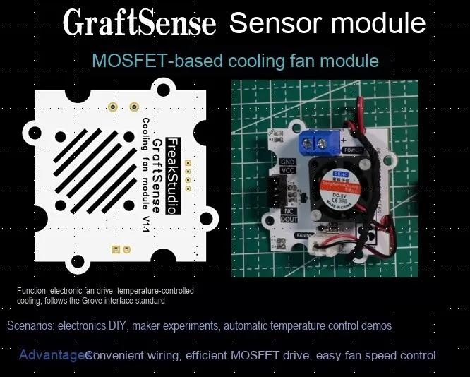
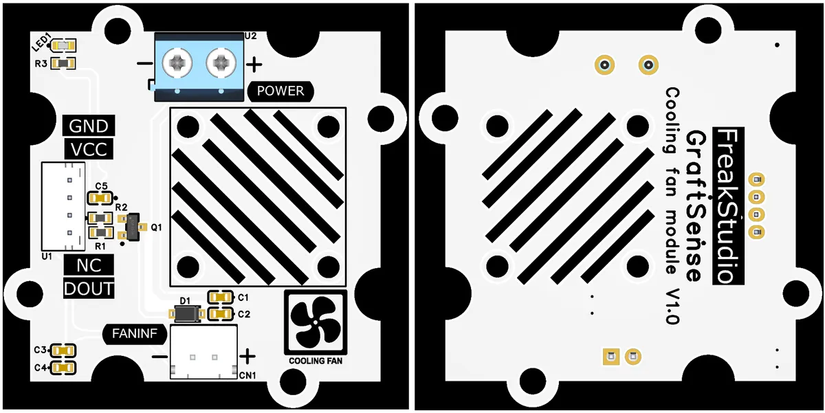
The cooling fan module based on MOS tube is designed based on MOS tube AO3400 . The PWM signal controls the conduction state of the MOS tube to adjust the fan speed. With the power interface, sensor interface, indicator light and filter circuit, it uses 5V power supply. It can accurately control the fan operation according to the equipment's cooling needs and provide efficient cooling solutions for electronic devices.
II. Introduction to Main Chips
2.1 Chip Overview
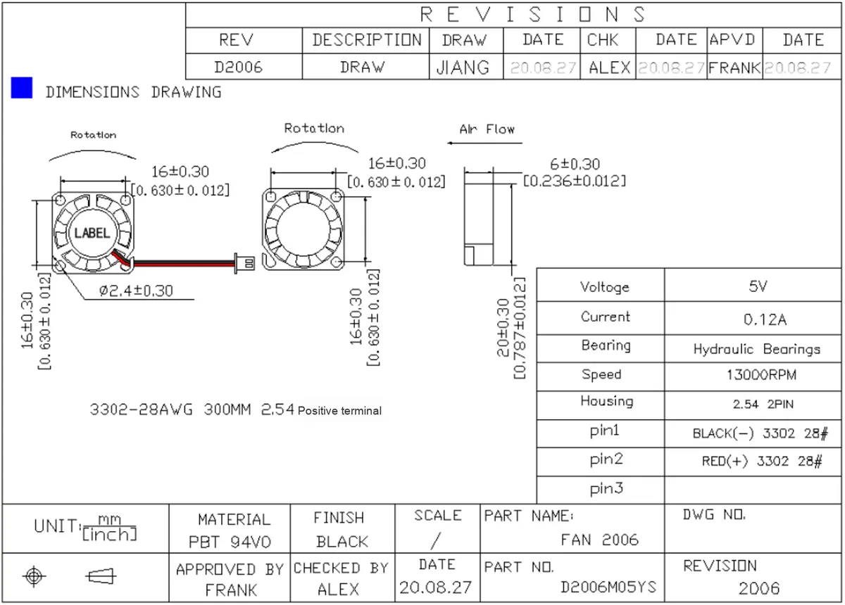
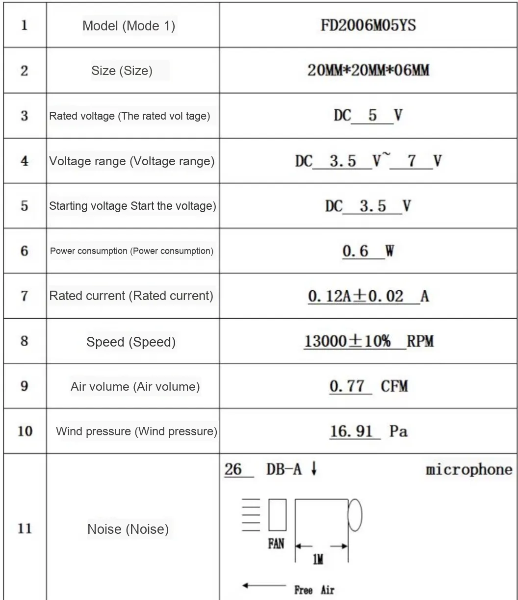
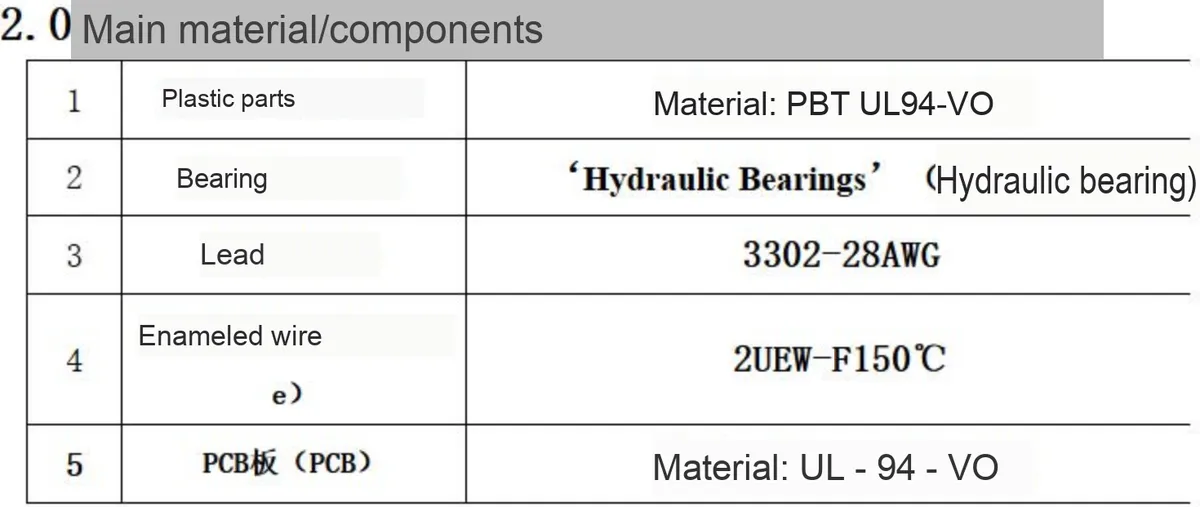
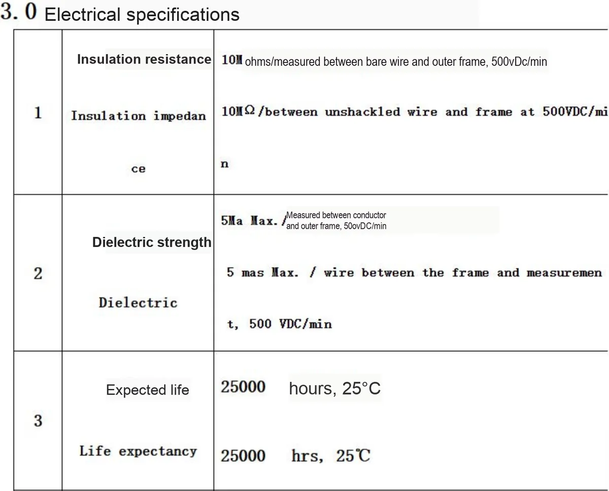
FD2006M05YS is a micro cooling fan, measuring 20mm×20mm×6mm, with a rated voltage of DC 5V, a voltage range of 3.5V~7V, power consumption of 0.6W, rated current of 0.12A±0.02A, a rotating speed of up to 13000±10% RPM, an airflow rate of 0.77 CFM, a static pressure of 16.91 Pa, and a noise level of only 26 DB-A.Adopts PBT UL94-V0 flame-retardant plastic parts, hydraulic bearings and UL94-V0 material PCB, with an expected service life of 25,000 hours (at 25°C), suitable for high-efficiency heat dissipation scenarios of small electronic devices.
2.2 Pin Definition
2.3 Functional Block Diagram
None.
2.4 Performance Parameters
2.5 Reference Circuit
None.
2.6 Chip Configuration
None.
2.7 Communication Interfaces and Related Protocols
None.
2.8 PCB Routing Precautions
None.
III. Instructions for Circuit Engineering and Module Usage
3.1 Circuit Source Engineering
To obtain the source code of the circuit, please follow the official account [Freak Embedded]
3.2 Module Usage Instructions
The schematic diagram of this module is shown below:
SCH_MOSFET-Based Cooling Fan Module_v1.0_2025-10-25.pdf 1.9 MB
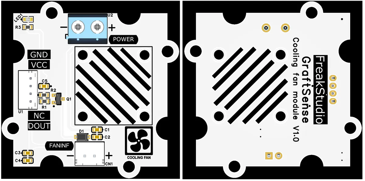
This module is controlled via the digital interface DOUT: The PWM output terminal of the MCU is connected to the DOUT terminal of the module. When the PWM output terminal outputs a high level, the DOUT MOS transistor turns on, and the external + 5V power supply powers the fan to run; when a low level is output, the + 5V MOS transistor turns off, and the fan is powered off and stops. To adjust the fan speed, PWM signals with different duty cycles can be output from the PWM output terminal to change the on-time ratio of the MOS transistor, thereby adjusting the fan speed. PWM PWM MOS
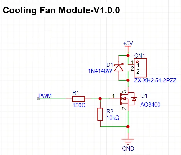
In this circuit, MOS FET AO3400 acts as a switching element, whose gate receives a R1 -coupled PWM control signal; the pull-down resistor R2 ensures the gate is stably grounded when no signal is present. When the PWM signal is at a high level, the MOS FET turns on, and the + 5V power supply feeds the cooling fan through the drain-source path; when the PWM signal is at a low level, the MOSFET cuts off and the fan is powered off.The 1N4148W diode acts as a freewheeling component to suppress the back EMF of the fan and protect the MOS FET. Meanwhile, the parameters of the AO3400, including a 30V drain-source withstand voltage and a 5.8A continuous drain current, fully meet the operating requirements of the fan at 5V and 0.12A, thus enabling precise on-off or speed regulation control of the cooling fan.
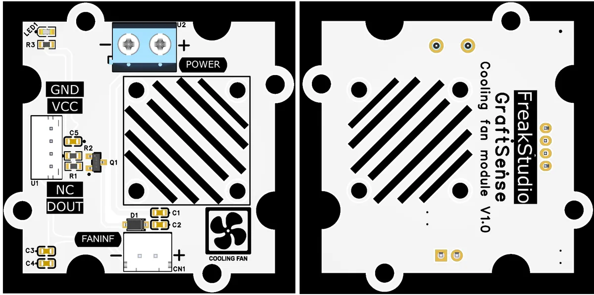
The FANINF interface of this module conforms to the XH2.54 specification, which is used to connect the cooling fan and transmit the control signals and power supply from the module to the fan;The POWER interface is used to connect an external + 5V DC power supply to provide independent power supply for the fan, so as to avoid interference caused by sharing a power supply with other circuits and ensure the stable operation of the fan.
3.3 Application Experiment
Here, we use the GraftPort-RP2040 development board for testing, and the MOSFET-based cooling fan module uses the DIO interface to communicate with the main controller.
Here, we first use the HY2.0-4P cable to connect the module to the GraftPort-RP2040 development board's DIO0 interface:
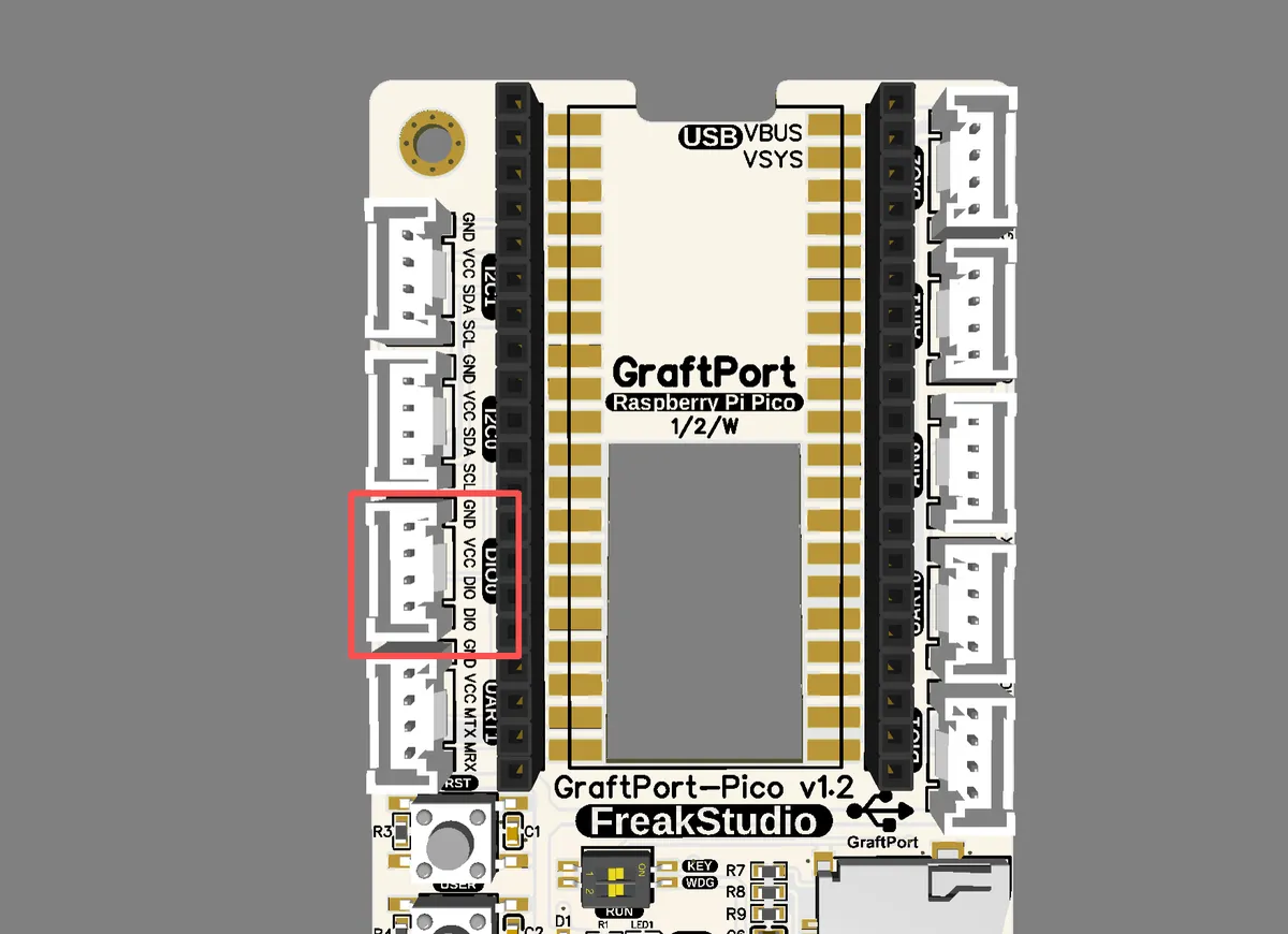
The module connections are shown in the following table:
Development Board Pins | Module Pins | Description |
Pin 6 |
| - |
Pin 7 |
| - |
Here, we need to search for relevant driver packages on uPyPI: https://upypi.net/zh/
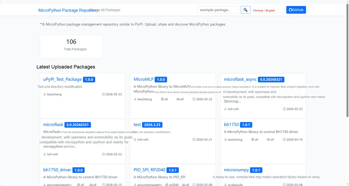
Enter fan_pwm_driver to search, and the following will be displayed:

Click to copy the local installation command:
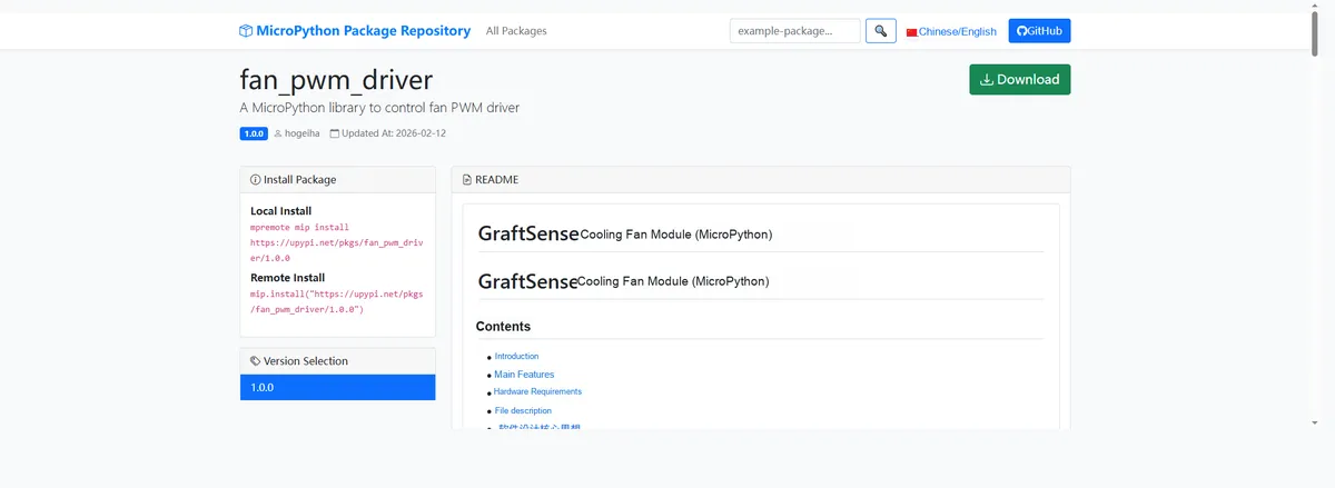
Here, we can use the mip tool to import module driver library code. Below are the usage commands for the mpremote tool:
mpremote mip install github:FreakStudioCN/GraftSense-Drivers-MicroPython/motor_drivers/fan_pwm_driverImport the MOSFET-based cooling fan module - MicroPython driver code, then copy the following main.py code into our project:
# Python env   : MicroPython v1.23.0
# -*- coding: utf-8 -*-
# @Time    : 2025/8/28 AM 11:22
# @Author  : 缪贵成
# @File    : main.py
# @Description : Test file for the PWM-driven cooling fan driver, testing different duty cycles

# ======================================== Import Modules =========================================

# Import time-related modules
import time
# Import the fan driver module
from fan_pwm import FanPWM

# ======================================== Global Variables ============================================

# ======================================== Functions ============================================

# ======================================== Custom Classes ============================================

# ======================================== Initialization configuration ===========================================

# Power-on delay of 3 s
time.sleep(3)
print("FreakStudio:Testing PWM cooling fans")

# Create a FANPWM object
fan = FanPWM(pin=6)

# ========================================  Main Program  ============================================

try:
    print("\n[Step 1] Turning fan ON (full speed)...")
    fan.on()
    print(f"Current duty: {fan.get_speed()}")
    time.sleep(5)

    print("\n[Step 2] Turning fan OFF...")
    fan.off()
    print(f"Current duty: {fan.get_speed()}")
    time.sleep(5)

    # Test different duty cycles
    for duty in [256, 512, 768, 1023]:
        print(f"\n[Step] Setting fan duty to {duty}...")
        fan.set_speed(duty)
        print(f"Current duty: {fan.get_speed()}")
        time.sleep(5)

    print("\n[Step 3] Testing digital property (Pin object)...")
    pin_obj = fan.digital
    print(f"Pin object: {pin_obj}")
    time.sleep(5)

    print("\n[Step 4] Testing pwm property (PWM object)...")
    pwm_obj = fan.pwm
    print(f"PWM object: {pwm_obj}")
    time.sleep(5)

except KeyboardInterrupt:
    print("\nTest interrupted by user.")

finally:
    print("\n[Cleanup] Turning fan OFF...")
    fan.off()
    print("Test complete.")
To flash the code, open a terminal and use the mpremote tool to connect to the main controller; the output is as follows:
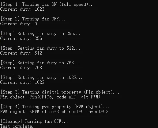
It can be seen that the fans on the module rotate at different speeds:
IV. Drivers
fan_pwm_driver.zip 11 KB
5. BOM & Recommended Alternative Parts
None.
VI. Revision History
Document Version | Date of Revision | Modifier | Revised Content |
v1.0 | 2025-08-31 | Hou Junhan Zero Kōkō | Complete the initial design and the preparation of hardware documents. |
v1.1 | 2025-10-25 | Li Zisheng | Added PCB layout precautions for Version 2.8 Revised Section 3, Instructions for Circuit Source Project and Module Usage, and added a secondary heading: 3.1 Circuit Source Engineering, 3.2 Module Usage Instructions, 3.3 Application Experiments The BOM sheet has not been finally checked, the driver has not been re-verified, and the 3.3 application experiment Not yet specified. |
v1.2 | 2025-12-29 | Li Zisheng | Added application experiments and production files |
v1.3 | 2025-12-31 | Xin Ruili | Create an open-version document based on the internal document version v1.2. |
v1.4 | 2026-03-29 | Xin Ruili | Modified the application experiment section |
VII. Relevant Materials
7.1 Chip Datasheet
Fan.pdf 163 KB
ao3400.pdf 5.5 MB
7.2 Unique Icons for PCB Silk Screen