Contents
- I. Module Introduction
- 2. Introduction to Main Chips
- 2.1 Chip Overview
- 2.2 Pin Definition
- 2.3 Functional Block Diagram
- 2.4 Performance Parameters
- 2.5 Reference Circuit
- 2.6 Chip Configuration
- 2.7 Communication Interfaces and Related Protocols
- 2.8 PCB Routing Precautions
- III. Instructions for Circuit Engineering and Module Usage
- 3.1 Circuit Source Engineering
- 3.2 Module Usage Instructions
- 3.3 Application Experiment
- 4. Drivers
- 5. BOM & Recommended Alternative Parts
- VI. Revision History
- VII. Relevant Materials
- 7.1 Chip Datasheet
- 7.2 Unique Icons for PCB Silk Screen
I. Module Introduction
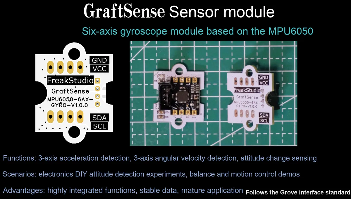
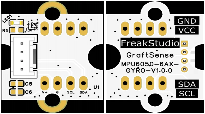
MPU6050-based 6-axis gyroscope module takes the ZY-MPU605 module as the core to build an attitude sensing solution, supports I2C communication and 5V power supply, integrates a power filter circuit, a power indicator and standard MCU interfaces; it is compatible with Grove interfaces, can simultaneously detect three-axis acceleration and angular velocity, provides stable data support for scenarios such as attitude detection, motion tracking and balance control, and features the practical characteristics of reliable power supply, convenient debugging and high scalability.
2. Introduction to Main Chips
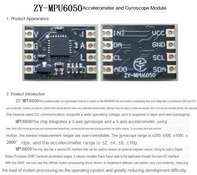
Adopts the ZY-MPU605 module.
2.1 Chip Overview
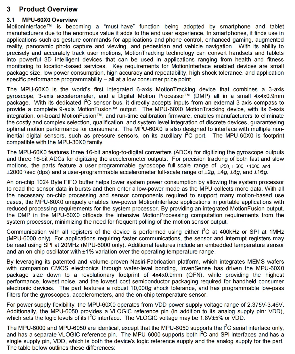
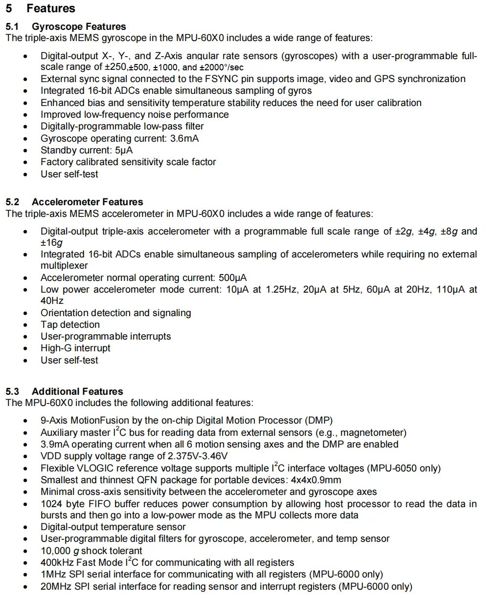
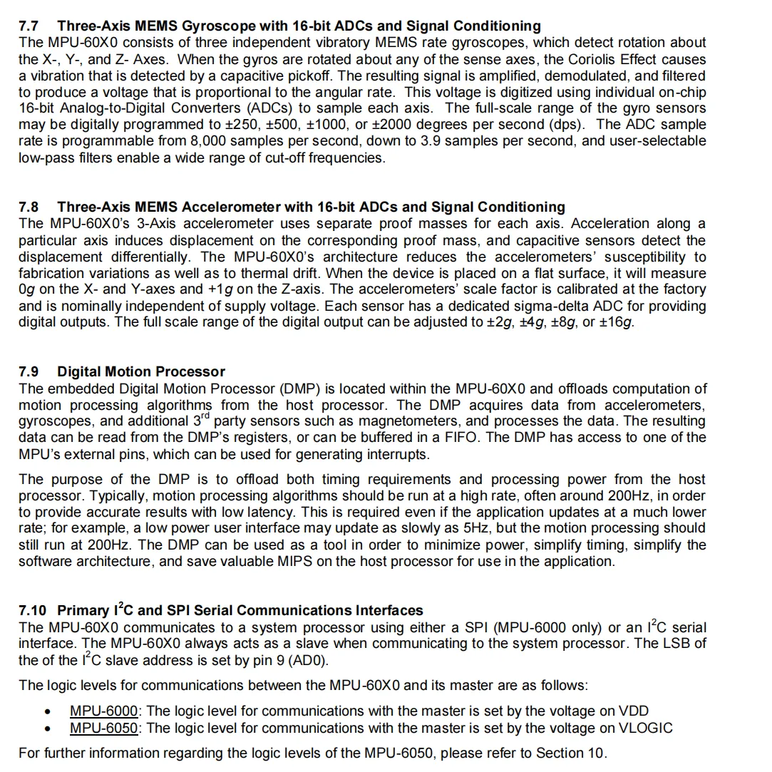
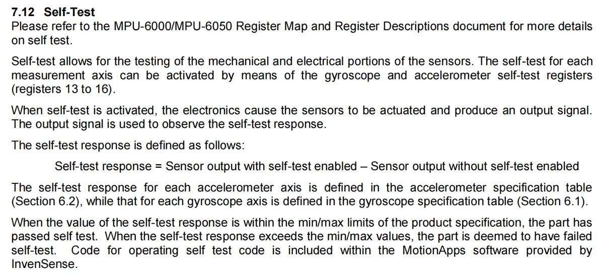
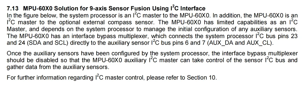
The MPU-60X0 is the world's first integrated 6-axis motion tracking device, which integrates a 3-axis gyroscope, a 3-axis accelerometer and a Digital Motion Processor (DMP) in a compact 4x4x0.9mm package, and can be externally connected to a 3-axis Compass to achieve complete 9-axis motion fusion output. It features programmable sensor ranges, low-power design and multiple communication interfaces, with high impact resistance and flexible power supply configuration, which can provide motion interaction functions such as gesture control, game enhancement and navigation for devices including smartphones and tablets, while simplifying system integration and reducing processor load.
2.2 Pin Definition
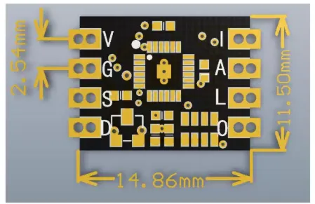
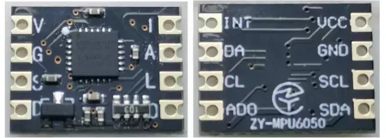
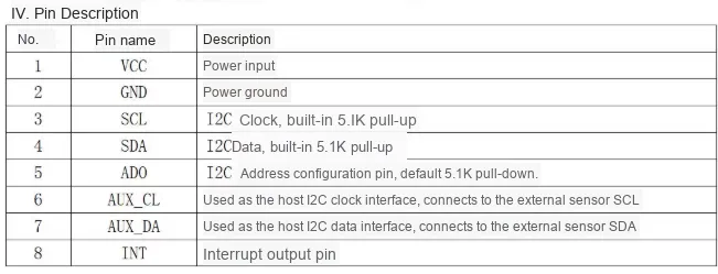
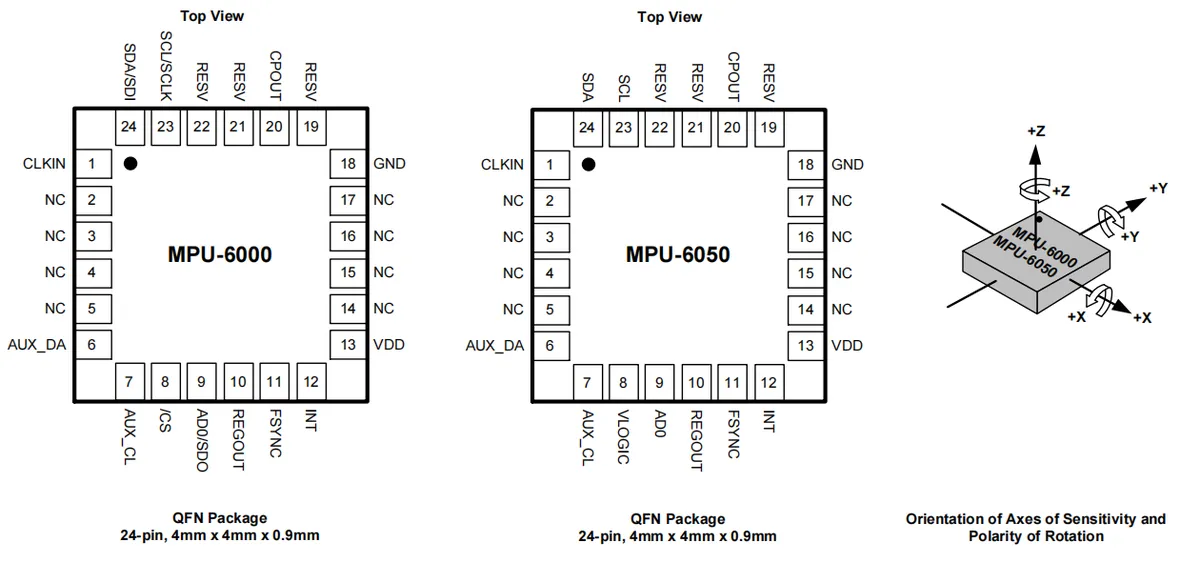
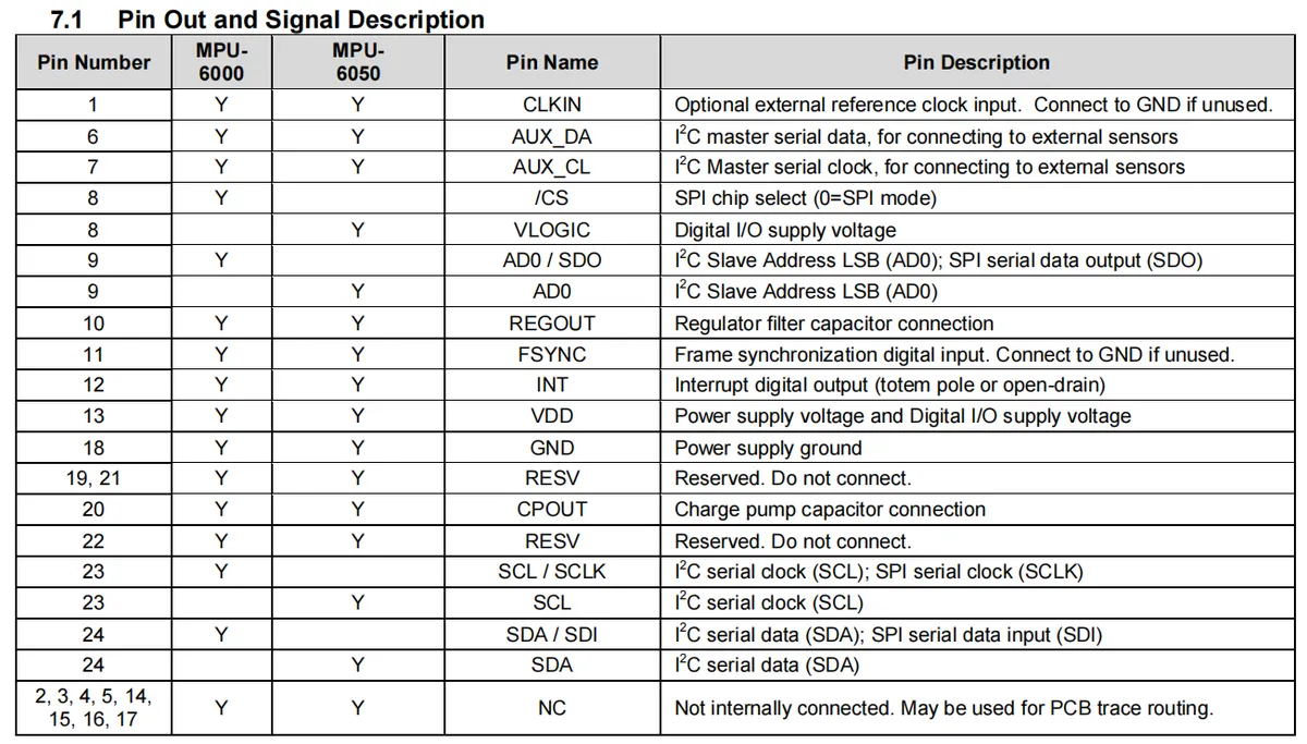
2.3 Functional Block Diagram
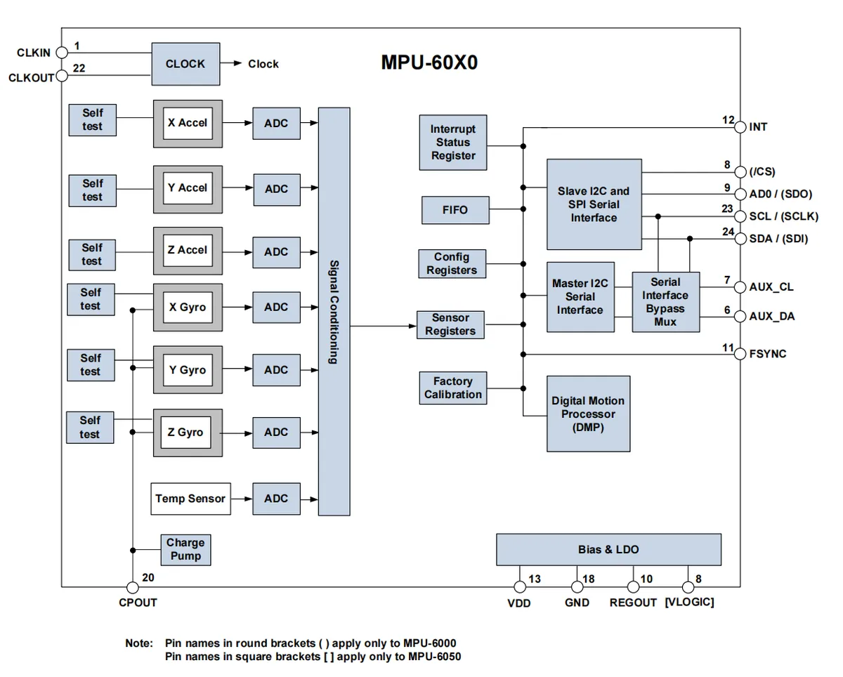
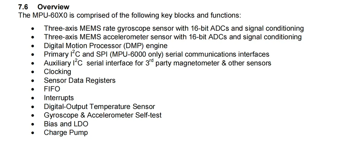
MPU-60X0 internal architecture: it integrates a 3-axis accelerometer, a 3-axis gyroscope and a temperature sensor, each sensing unit is equipped with a self-test module and a 16-bit ADC, which sends data to the sensor register after signal conditioning;The chip integrates a built-in digital motion processor (DMP), a FIFO buffer, interrupt status registers and configuration registers. It implements data communication via master/slave I²C and SPI (supported only by MPU-6000) interfaces, and also supports an auxiliary I²C interface for expanding external sensors. Meanwhile, it integrates clock, charge pump and bias LDO power modules, capable of completing the acquisition, processing, storage and transmission of 6-axis motion data, and supports external clock input and output, providing complete motion sensing and processing capabilities for devices.
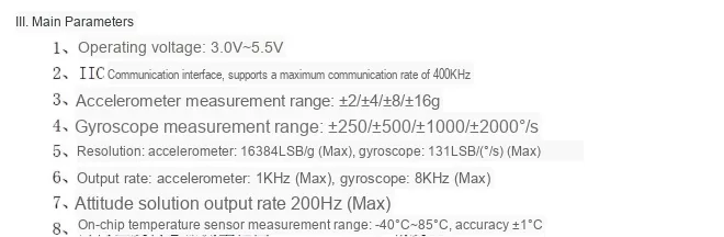
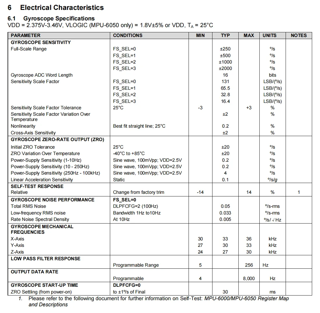
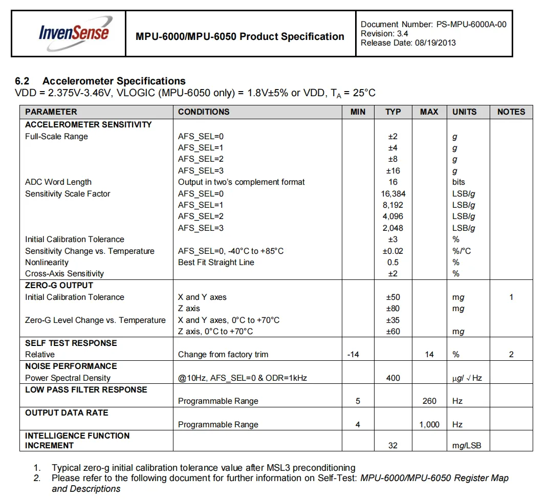
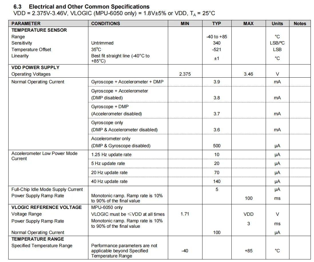
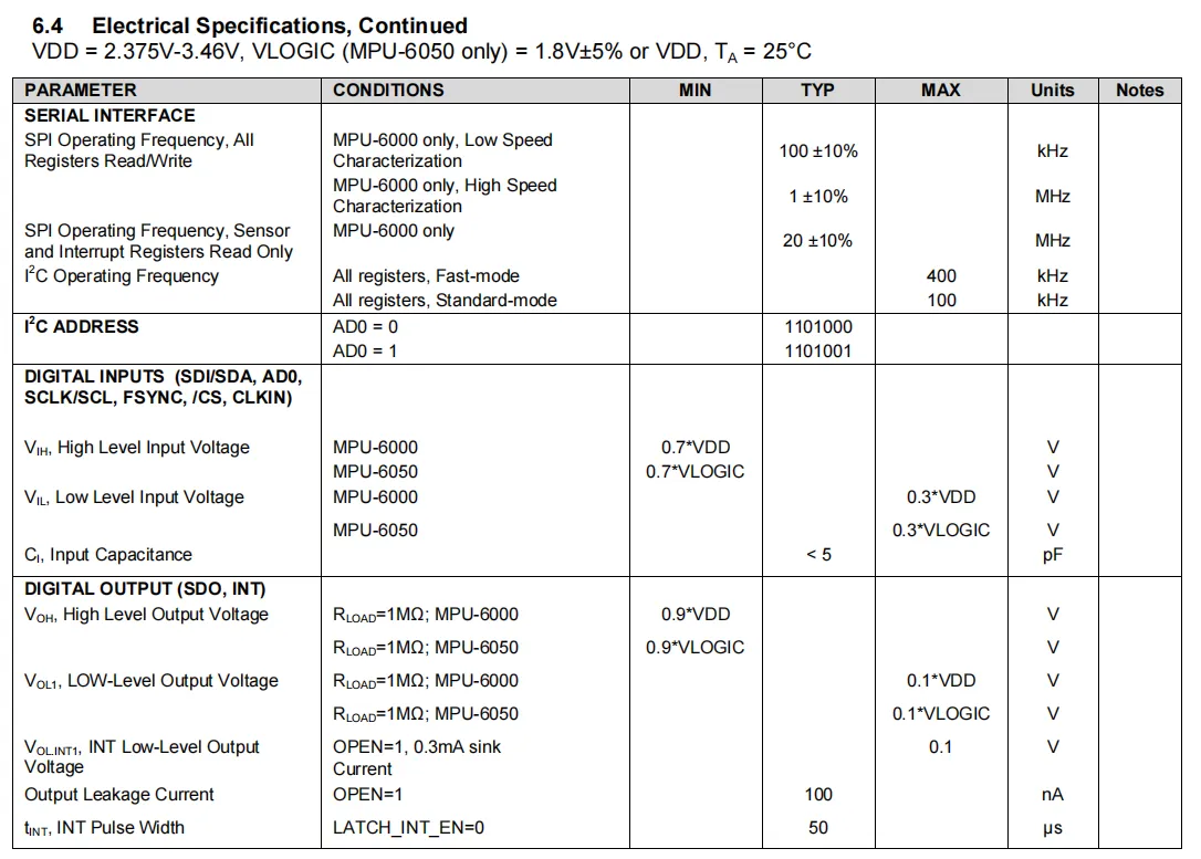
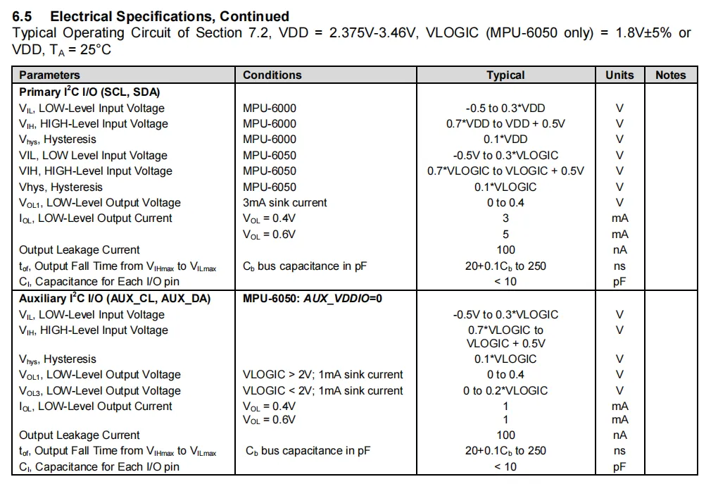
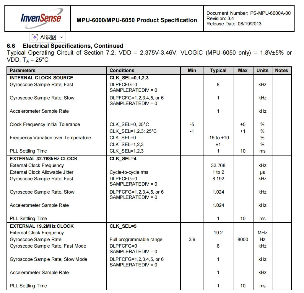
2.4 Performance Parameters
2.5 Reference Circuit
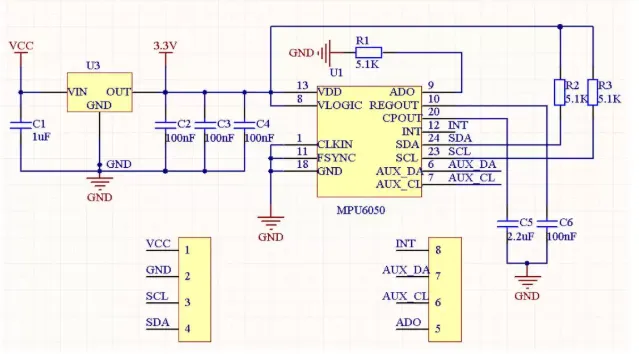
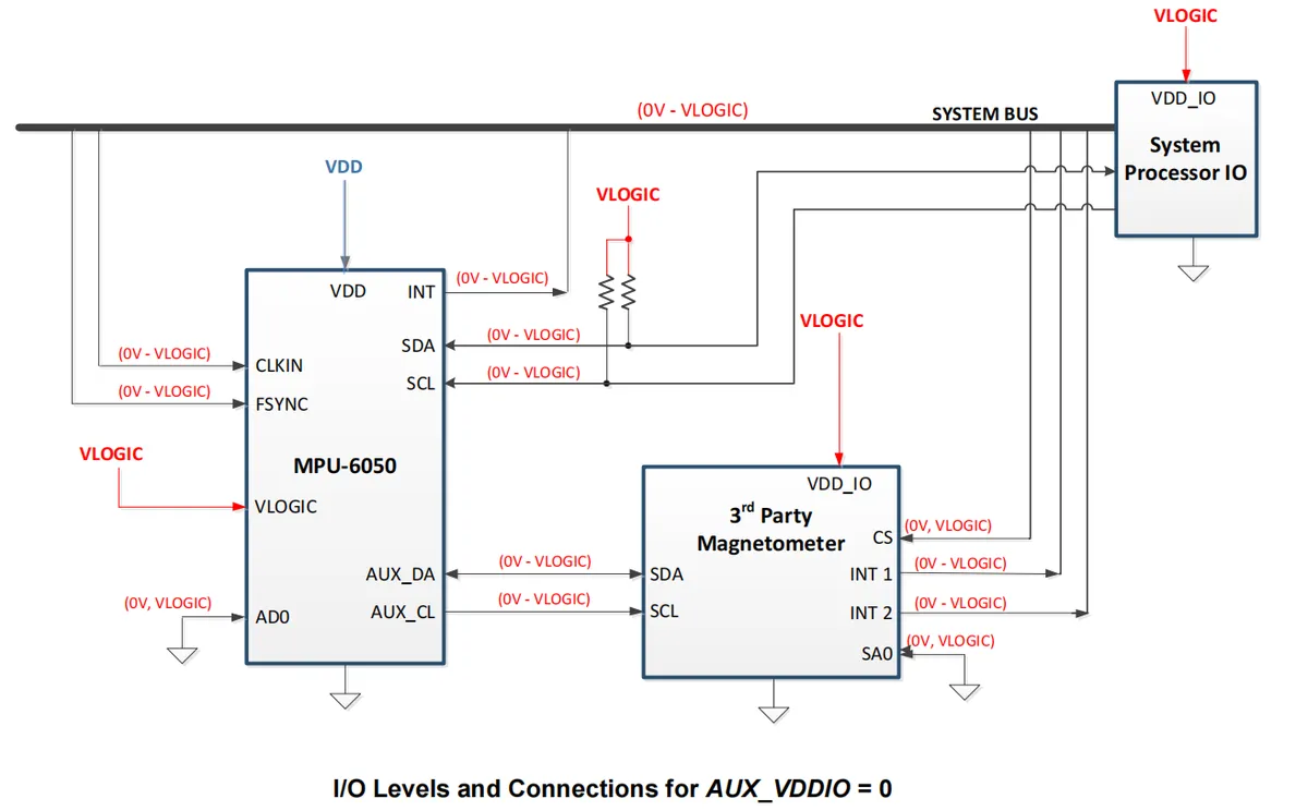
2.6 Chip Configuration
We can set the chip address by adjusting the pins of chip AD0:
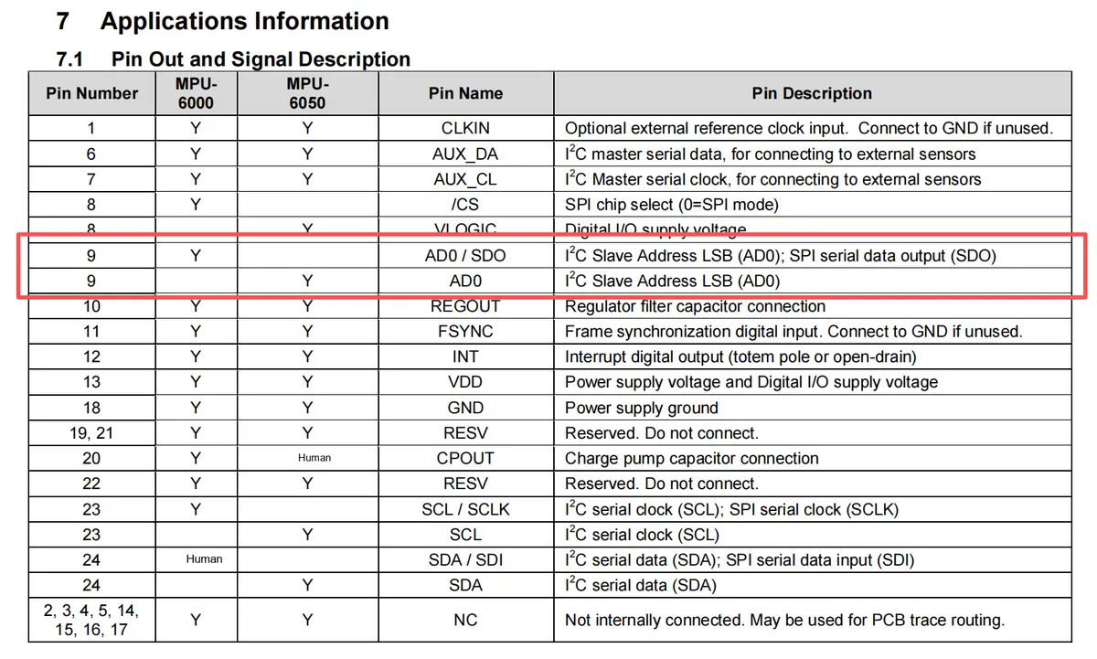
2.7 Communication Interfaces and Related Protocols
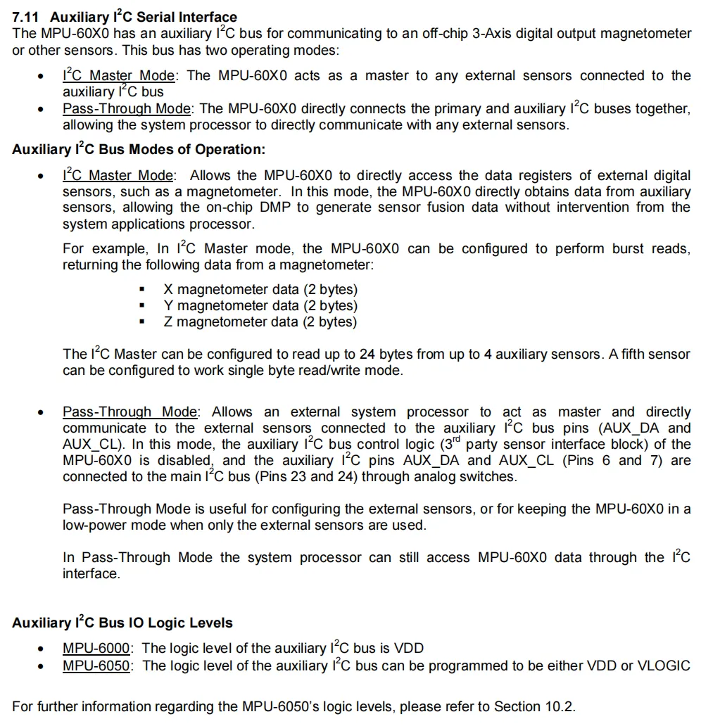
The communication interfaces of the MPU-60X0 include three types: main I²C, SPI (supported only by the MPU-6000), and auxiliary I²C.
- Master I²C Interface: Supports Fast Mode (400kHz) and Standard Mode (100kHz). The MPU-60X0 acts as a slave device to communicate with the system processor, and the slave address is determined by the logic level of the AD0 pin.
- SPI interface: Only supported by the MPU-6000, it features three rate modes: low speed (100kHz), high speed (1MHz), and a 20MHz mode dedicated to reading sensor and interrupt registers, catering to the communication requirements of diverse scenarios.
- Auxiliary I²C Interface: Supports master mode and pass-through mode. In master mode, the MPU-60X0 can directly read data from external sensors (such as a magnetometer) for the DMP to generate fused data; in pass-through mode, the system processor is allowed to directly control external sensors, which is suitable for sensor configuration scenarios.
In terms of logic levels, the communication logic level of the MPU-6000 is determined by VDD, while the main I²C logic level of the MPU-6050 is determined by VLOGIC, and its auxiliary I²C logic level can be configured as either VDD or VLOGIC. The interface protocols comply with the standard specifications of I²C and SPI, and sensor control and data interaction are completed through register configuration and data transmission.
2.8 PCB Routing Precautions
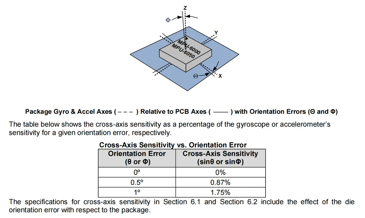
For assembly and PCB design, the following points require attention:
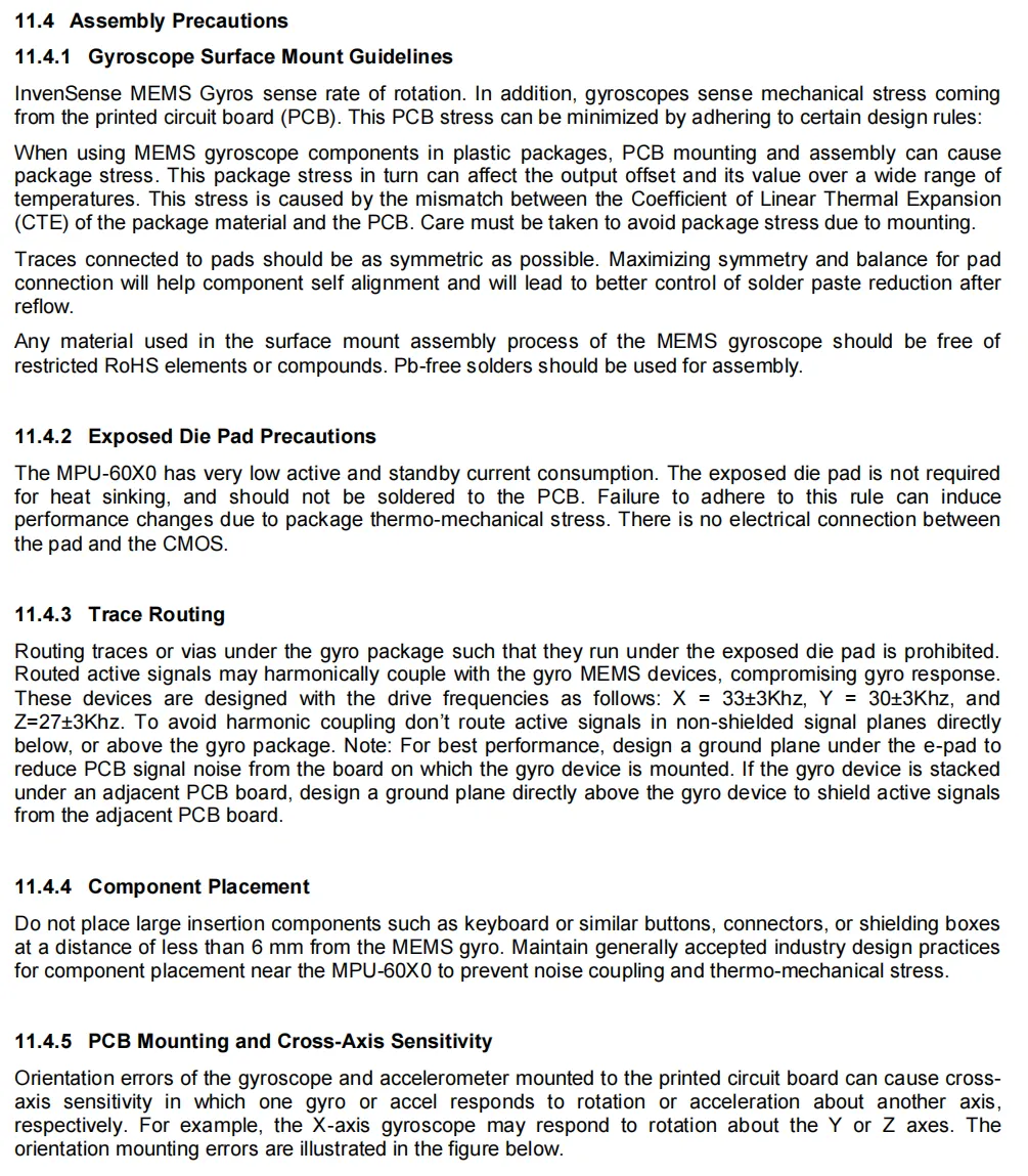
- When surface-mounting the gyroscope, ensure that the PCB traces are symmetrical to reduce thermomechanical stress and use lead-free soldering; soldering to the exposed chip pad is prohibited, as this will induce stress and cause performance drift.
- Signal lines are prohibited from routing under the device (especially in the exposed pad area). A ground plane shall be laid to reduce noise coupling. Large-sized components shall be kept at a distance of more than 6mm from the gyroscope to avoid interference and stress.
- PCB mounting angle error will cause cross-axis sensitivity issues, and mounting errors of 0.5° and 1° will lead to cross-axis responses of approximately 0.87% and 1.75%, respectively.
III. Instructions for Circuit Engineering and Module Usage
3.1 Circuit Source Engineering
To obtain the circuit source project, please follow the official account [Freak Embedded].
3.2 Module Usage Instructions
The schematic diagram of this module is shown below:
SCH_Six-Axis Gyroscope Module Based on MPU6050-v1.0_2026-01-29.pdf 2.4 MB
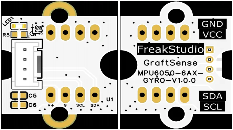
This module provides an IIC communication interface: it supports standard I2C communication rates, with its I2C address being 0x68, it is compatible with 3.3V/5V logic levels, can stably transmit the three-axis acceleration and three-axis angular velocity data collected by the MPU6050, is suitable for scenarios such as attitude detection, motion tracking and balance control, and provides reliable interactive capability of attitude sensing data for the system.
3.3 Application Experiment
Here, we use the GraftPort-RP2040 development board for testing, and connect the MPU6050-based six-axis gyroscope module to communicate with the main controller via the UART interface.
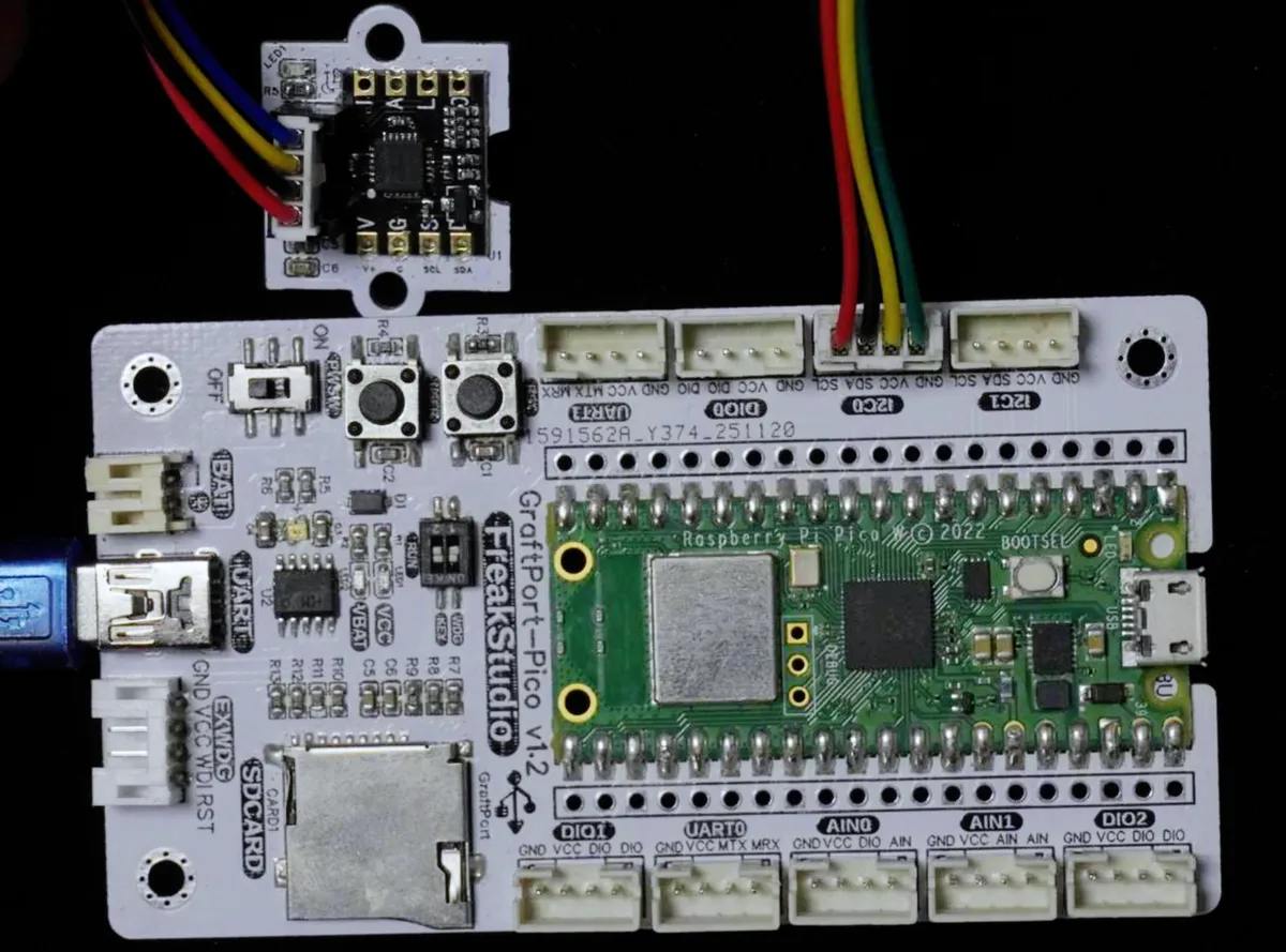
Here, we first use the HY2.0-4P cable to connect the module to the GraftPort-RP2040 development board's I2C0 interface:
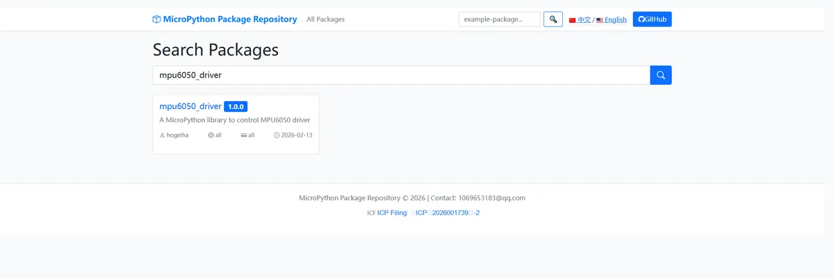
Here, we need to search for the relevant driver packages on uPyPI: https://upypi.net/zh/
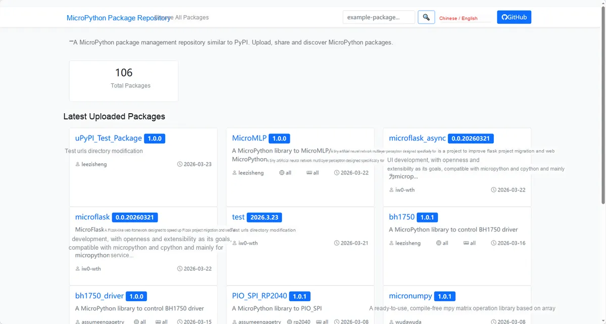
Enter mpu6050_driver to search, and the following will be displayed:
Click to copy the local installation command:
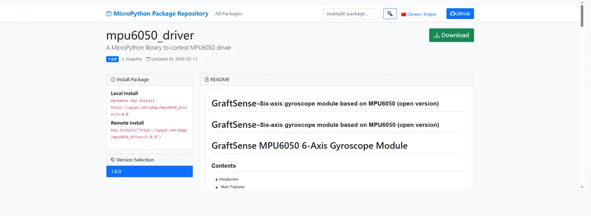
Here, we can import the module driver library code via the mip tool. Below are the usage commands for the mpremote tool:
mpremote mip install github:FreakStudioCN/GraftSense-Drivers-MicroPython/sensors/mpu6050_driverImport the MPU6050-based 6-axis gyroscope module - MicroPython driver code, then copy the following main.py code into our project:
# Python env   : MicroPython v1.26.1
# -*- coding: utf-8 -*-
# @Time    : 2026/1/15 10:32 AM
# @Author  : hogeiha
# @File    : main_mpu6050_gyro_kalman.py
# @Description : MPU6050 gyroscope and Kalman filter angle comparison

# ======================================== Import Modules ========================================

from machine import UART, Pin, SoftI2C
import time
import gc
from mpu6050 import MPU6050, ComplementaryKalmanFilter
from math import degrees

# ======================================== Global Variables ============================================

# Program start time variable
start_time = 0
# MPU default address
MPU6050_ADDRESS = 0x68

# ======================================== Initialization ==========================================

# Power-on delay of 3 s
time.sleep(3)
print("MPU6050 Gyroscope and Kalman Filter Angle Comparison Program")

# Create the serial port object, set the baud rate to 115200
uart = UART(1, 115200)
# Initialize the uart object: 8 data bits, no parity bit, 1 stop bit
# Set the UART timeout to 5 ms
uart.init(bits=8,
          parity=None,
          stop=1,
          tx=8,
          rx=9,
          timeout=5)

# Set GPIO 25 as the LED output pin
LED = Pin(25, Pin.OUT, Pin.PULL_DOWN)

# Initialize the I2C interface
i2c = SoftI2C(scl=Pin(5), sda=Pin(4), freq=100000)

# Start scanning for devices on the I2C bus and return a list of slave addresses
devices_list = i2c.scan()
print('START I2C SCANNER')

# If devices_list is empty, no device is connected to the I2C bus
if len(devices_list) == 0:
    print("No i2c device !")
# If not empty, print the slave device addresses
else:
    print('i2c devices found:', len(devices_list))
    # Iterate over the slave device address list
    for device in devices_list:
        print("I2C hexadecimal address: ", hex(device))
        if device == 0x68 or device == 0x69:
            MPU6050_ADDRESS = device
mpu = MPU6050(i2c = i2c, addr= MPU6050_ADDRESS)

print("MPU6050 initialized successfully")

# Create a complementary Kalman filter
filter = ComplementaryKalmanFilter(dt=0.01, gyro_weight=0.98)
print("Kalman filter initialized successfully")

# Gyroscope integrated angle (for comparison only)
gyro_roll_deg = 0.0
gyro_pitch_deg = 0.0

# Last update time
last_update_time = time.ticks_ms()

LED.on()
time.sleep(0.5)
LED.off()
time.sleep(0.5)

# ========================================  Main Program  ============================================

try:
    # Print the table header
    print("\n" + "=" * 90)
    print("Time (s) | Gyroscope_Roll | Kalman_Roll | Gyroscope_Pitch | Kalman_Pitch | Temperature (°C)")
    print("-" * 90)

    # Record the start time
    start_time = time.ticks_ms()

    while True:
        # Turn on the LED
        LED.on()

        try:
            # Read accelerometer data
            accel_data = mpu.read_accel_data(g=False)

            # Read gyroscope data
            gyro_data = mpu.read_gyro_data()

            # Read temperature data
            temperature = mpu.read_temperature()

            # Calculate the time interval
            current_time = time.ticks_ms()
            dt = time.ticks_diff(current_time, last_update_time) / 1000.0
            last_update_time = current_time

            # Calculate the run time
            elapsed_time = time.ticks_diff(current_time, start_time) / 1000.0

            # Update the gyroscope integrated angle (gyroscope only)
            if dt > 0 and dt < 0.1:  # Prevent abnormal time interval
                gyro_roll_deg += gyro_data['y'] * dt  # Roll corresponds to the gyroscope Y axis
                gyro_pitch_deg += gyro_data['x'] * dt  # Pitch corresponds to the gyroscope X axis

            # Use the Kalman filter to update the angle estimate (accelerometer + gyroscope fusion)
            kalman_roll_rad, kalman_pitch_rad = filter.update_roll_pitch(accel_data, gyro_data)
            kalman_roll_deg = degrees(kalman_roll_rad)
            kalman_pitch_deg = degrees(kalman_pitch_rad)

            # Extract raw angular velocity and acceleration data
            gyro_x = gyro_data['x']
            gyro_y = gyro_data['y']
            gyro_z = gyro_data['z']

            accel_x = accel_data['x']
            accel_y = accel_data['y']
            accel_z = accel_data['z']

            # Print the complete data (including angular velocity and acceleration)
            print("%7.2f | %10.2f° | %10.2f° | %11.2f° | %11.2f° | %6.1f°C | %5.1f/%5.1f/%5.1f | %4.2f/%4.2f/%4.2f" % (
                elapsed_time,
                gyro_roll_deg,
                kalman_roll_deg,
                gyro_pitch_deg,
                kalman_pitch_deg,
                temperature,
                gyro_x, gyro_y, gyro_z,
                accel_x, accel_y, accel_z
            ))

            # Prepare data to send to the host computer
            # Serial send format: angle data - Gyro_Roll,Kalman_Roll,Gyro_Pitch,Kalman_Pitch
            angle_data = "{:.2f}, {:.2f}, {:.2f}, {:.2f}\r\n".format(
                gyro_roll_deg,
                kalman_roll_deg,
                gyro_pitch_deg,
                kalman_pitch_deg,
            )

            # Send data to the host computer via serial port (you can choose which format to send as needed)
            # Send angle data
            uart.write(angle_data)

            # To send raw data, uncomment the line below
            # uart.write("RAW," + raw_data)

            # Turn off the LED
            LED.off()

            # Delay to control the sampling rate
            time.sleep_ms(50)  # 20Hz sampling rate

            # Reset the gyroscope integrated angle every 50 samples (to avoid drift accumulation)
            # 20Hz sampling rate
            static_sample_count = int(elapsed_time * 20)
            # Detect whether the device is stationary (acceleration magnitude close to 9.8)
            if static_sample_count % 50 == 0 and static_sample_count > 0:
                accel_magnitude = (accel_x ** 2 + accel_y ** 2 + accel_z ** 2) ** 0.5
                # Device is relatively stationary
                if 9.0 < accel_magnitude < 10.5:
                    # Reset the gyroscope integration using the Kalman filter angle
                    gyro_roll_deg = kalman_roll_deg
                    gyro_pitch_deg = kalman_pitch_deg
                    if static_sample_count % 100 == 0:
                        print("\n[Device Stationary] Resetting gyroscope integrated angle...")
                        print(f"[Current Acceleration Magnitude]: {accel_magnitude:.2f} g]")

            # Garbage collection
            if gc.mem_free() < 80000:
                gc.collect()
                print("[GC] Memory cleanup, available memory: {} bytes".format(gc.mem_free()))

        except Exception as e:
            print("Error reading data:", e)
            LED.off()
            time.sleep(0.1)

except KeyboardInterrupt:
    print("\nThe program was interrupted by the user")
finally:
    LED.off()
    print("Program exited")
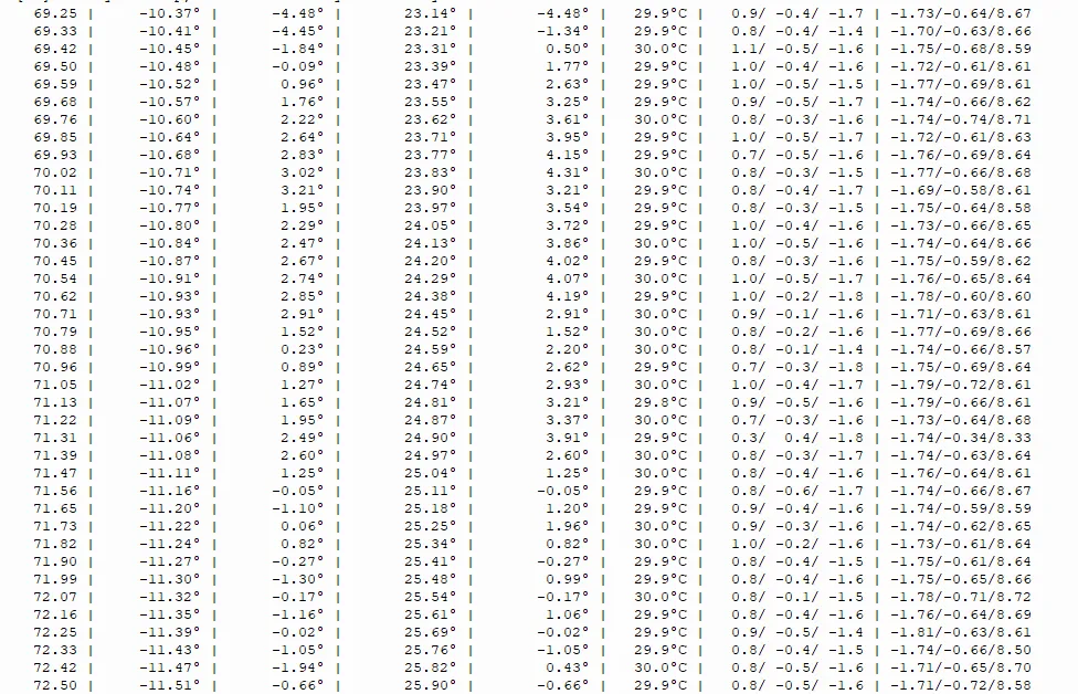
The terminal output is as follows:
"Time (s) | Gyroscope_Roll | Kalman_Roll | Gyroscope_Pitch | Kalman_Pitch | Temperature (°C)"
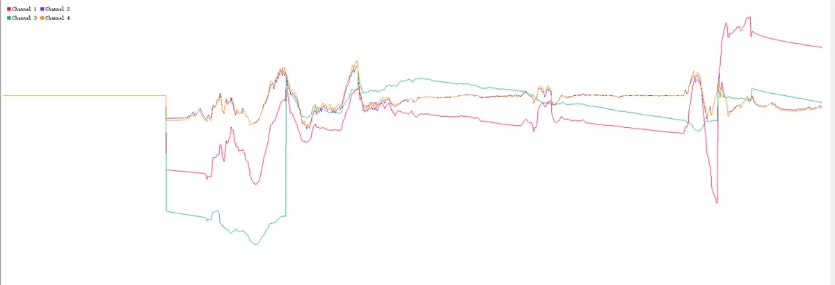
We can also view the signal waveform in the serial plotter of Thonny:
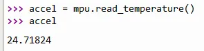
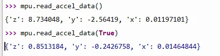
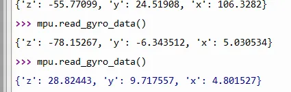
We can also test the relevant methods in REPL:
4. Drivers
mpu6050_driver.rar 12 KB
5. BOM & Recommended Alternative Parts
None.
VI. Revision History
Document Version | Date of Modification | Modifier | Revised Content |
v1.0 | 2025-11-22 | Li Zisheng | Initialize Document |
v1.1 | 2026-02-12 | Xin Ruili | Create an open version of the document based on the internal document version v1.0. |
v1.2 | 2026-03-29 | Xin Ruili | Modified the application experiment section. |
VII. Relevant Materials
7.1 Chip Datasheet
7.2 Unique Icons for PCB Silk Screen