
Contents
- Introduction
- I. Module Introduction
- II. Introduction to Major Chips
- 2.1 Chip Overview
- 2.2 Pin Definition
- 2.3 Functional Block Diagram
- 2.4 Performance Parameters
- 2.5 Reference Circuit
- 2.6 Chip Configuration
- 2.7 Communication Interfaces and Related Protocols
- 2.8 Register Definition
- III. Circuit Engineering
- 3.1 Circuit Source Engineering
- 3.2 Module Usage Instructions
- 3.3 Application Experiment
- 4. Drivers
- 5. BOM & Recommended Alternative Parts
- VI. Revision History
- VII. Relevant Materials
Introduction
In application scenarios such as grain silos, cold chain storage, greenhouse facilities, livestock farms, and industrial equipment, the accuracy and stability of temperature and humidity data directly affect material safety, production quality, and equipment operation. However, ordinary temperature and humidity sensors are always prone to problems such as "probe contamination, humidity drift, line interference, and degraded long-term stability" in environments with high humidity, condensation, dust, and corrosive gases, which frequently cause environmental monitoring systems to fail unexpectedly.

Traditional temperature and humidity detection solutions all have their limitations: ordinary exposed humidity-sensitive probes are prone to adsorbing dust and oil stains, and their measurement values may drift after long-term use; in environments with high humidity or rapid temperature changes, condensation easily forms on the probe surface, causing the humidity reading to stay at full scale for a long time or recover slowly; analog signal solutions are susceptible to cable voltage drop and electromagnetic interference, making them unsuitable for long-distance, multi-node deployment; some low-cost digital sensors have limited protection and environmental adaptability, making it difficult for them to work for a long time in environments with salt spray, corrosive gases, and alternating high and low temperatures.
The MHT04/MHT04H temperature and humidity sensor from Minyuan Sensor is an industrial-grade detection solution designed specifically to address these issues. Equipped with a platinum laminated humidity-sensitive probe and the high-precision capacitance conditioning chip MDC04, this product is capable of simultaneously collecting temperature and humidity-sensitive capacitance data, and completing humidity conversion and temperature compensation using factory calibration coefficients. The sensor supports 1-Wire or I²C digital communication, and features wide voltage range, low power consumption, digital transmission, and multi-node deployment.The MHT04H is equipped with an additional waterproof and breathable membrane outside the humidity-sensitive probe, and its humidity-sensitive capacitor and chip pins are coated with a protective layer, enabling it to better adapt to high-humidity, condensation, salt spray and corrosive environments.
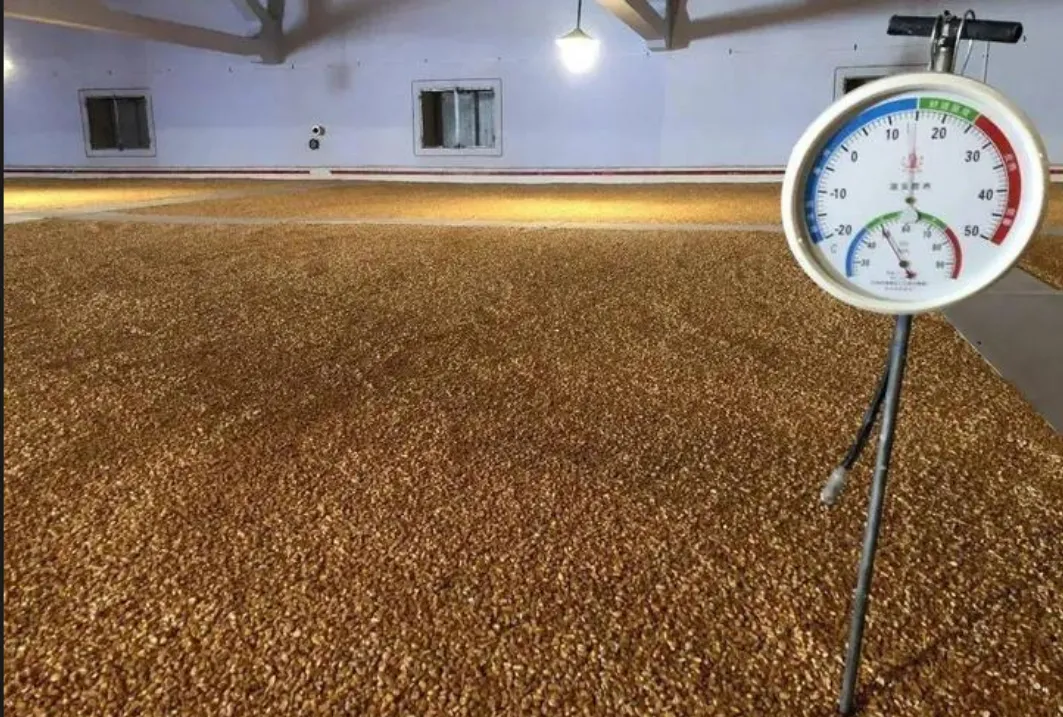
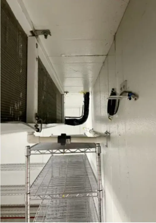
In scenarios such as grain silos, food storage and cold chain transportation, changes in temperature and humidity directly affect the storage quality of grain, pharmaceuticals and food. Excessively high humidity easily leads to mildew, condensation and damp packaging, while excessively low humidity may cause material dehydration or quality deterioration. The MHT04/MHT04H can be deployed at different locations in warehouses, grain silos, freezers and transport containers to continuously collect ambient temperature and humidity data; the one-wire version is suitable for long-distance, multi-node networking, which can reduce on-site wiring and the number of collection nodes, and provides a reliable data basis for storage environment early warning, ventilation and dehumidification, and cold chain quality traceability.
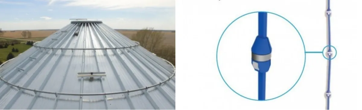
It is recommended to display the interior of a large granary or cold storage, mark multiple temperature and humidity collection points at different heights, and use connecting lines to indicate that multiple nodes are connected to the monitoring host.
In scenarios such as greenhouses, seedling cultivation rooms, and livestock and poultry breeding sites, temperature and humidity are key environmental parameters that affect crop growth, disease occurrence and animal health. The MHT04/MHT04H can be installed in planting areas, ventilation openings, seedling racks or livestock houses to feed back environmental changes in real time, and link with fans, humidifiers, dehumidifiers, sprinklers and temperature control equipment. Featuring low power consumption and compact size, the sensors are suitable for distributed deployment; the protective structure of the MHT04H can also mitigate the impact of high humidity, spray and condensation on the humidity-sensitive probe, providing a stable sensing foundation for agricultural environmental control.
In industrial equipment, cabinets, pipe galleries and corrosive environments, the heat, moisture and temperature difference generated during equipment operation may lead to condensation, insulation degradation, metal corrosion and even electrical failures. The MHT04H can be installed in key locations such as control cabinets, energy storage cabinets, instrument compartments and industrial pipe galleries to continuously monitor local temperature and humidity. For scenarios where the sensing position needs to be separated from the control circuit, a metal temperature and humidity probe is optional, which can be arranged in narrow spaces or high-humidity areas via a customized cable.Its digital communication method can reduce the errors of analog signals during long-distance transmission, and provide data support for equipment condensation prevention control, fault early warning and environmental reliability management.
I. Module Introduction
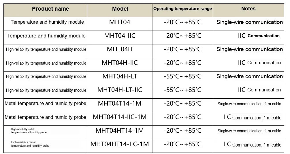
MHT04 (H) is an industrial-grade integrated temperature and humidity acquisition sensor. The humidity channel uses a humidity-sensitive capacitor as the sensing element, and the MDC04 completes the acquisition of capacitance and temperature; the host computer reads the factory calibration coefficients from the EEPROM, converts the capacitance value into relative humidity and performs temperature compensation.
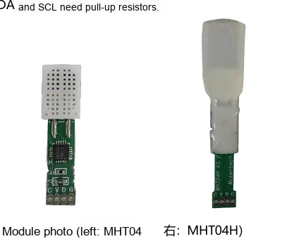
- MHT04: Standard type, with dimensions of approximately 27mm × 7mm × 3.9mm, suitable for conventional environments and in-board integration.
- MHT04H: High reliability, with dimensions of approximately 43.5mm × 10.0mm × 7.0mm, and equipped with an additional waterproof breathable membrane and protective coating.
- Interface version: 1-Wire or I²C; additionally, there are -LT low-temperature version and the version with a metal temperature and humidity probe of 14mm in diameter.
- Under the conditions of a 5V power supply and a 1kΩ pull-up resistor, the 1-Wire bus can connect approximately 100 nodes in series. The maximum cable length specified in the datasheet is 500m for reference only; engineering designs shall still be verified in combination with the wire type, electromagnetic environment and timing margin.
II. Introduction to Major Chips
2.1 Chip Overview
MDC04 is a capacitance conditioning and temperature acquisition chip. It outputs the original temperature value and the original value of the humidity-sensitive capacitor, and does not directly output the final relative humidity by itself. MHT04 (H) has completed multi-point calibration before leaving the factory, and coefficients such as slope HumA and offset HumB have been written into the internal EEPROM; the main controller completes the conversion of capacitance, humidity and temperature compensation according to the formula.
Data chain: Original temperature/capacitance → Calibration coefficient reading → Capacitance conversion → Relative humidity calculation → Temperature compensation → 0~100%RH limiting.
2.2 Pin Definition
API | symbol | Single-bus Version | I²C Version |
communication | C | Unused | SCL clock line |
communication | D | DQ Data Cable | SDA data cable |
Power Supply | G | GND | GND |
Power Supply | V | VCC (2.0V~5.5V) | VCC (2.0V~5.5V) |
For the I²C version, both SDA and SCL need to be pulled up to VCC; for the 1-Wire version, only DQ requires a pull-up. For cable-type probes, the red wire is typically used for power, black for ground, and yellow for data line; the I²C version additionally has a clock line; the final specification shall be subject to the physical label and order configuration.
2.3 Functional Block Diagram
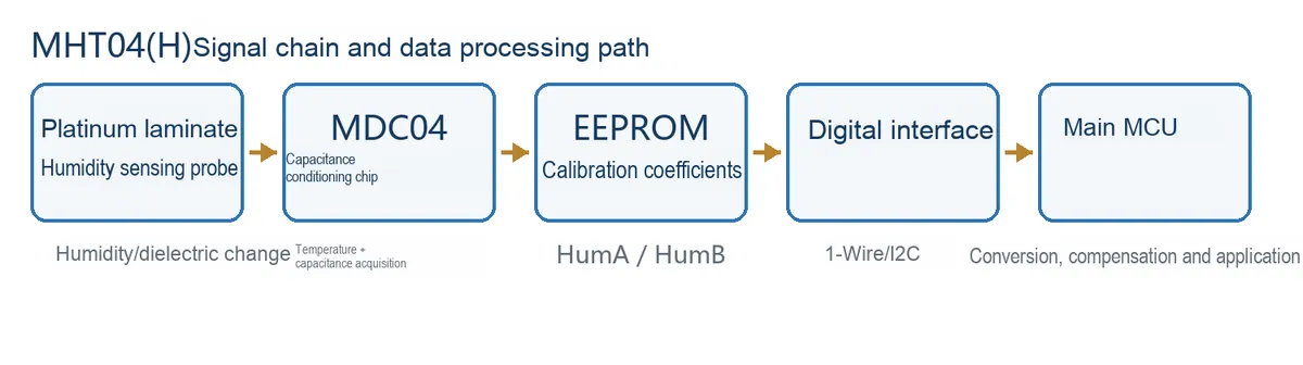
The protective structure of the MHT04H is located on the side of the humidity-sensitive probe and does not alter the data processing flow of the MDC04. The coefficients stored in the EEPROM are individual calibration data specific to each module and shall not be copied between different devices.
2.4 Performance Parameters
Project | Typical/Specified Value | Description |
Power Supply Coverage | 2.0V~5.5V | Module operating voltage |
Average Power Consumption | 4.5μA@3V | Typical value in manual |
Humidity Range | 0~100%RH | It is recommended to limit the range to 0~100%RH |
Typical humidity accuracy | ±2.0%RH | MHT04: 30~70%RH; MHT04H: 50~95%RH |
humidity resolution | 0.01%RH | Convert output resolution |
Typical Temperature Accuracy | ±0.2℃ | +20℃~+35℃ |
Typical Temperature Accuracy | ±0.5℃ | 0℃~+50℃ |
Temperature accuracy | ±1.5℃ | -20℃~+85℃ |
Low-temperature accuracy | ±2℃ | -55℃~-20℃, applicable to LT models |
temperature resolution | 0.004℃ | The LSB of the original value is 1/256°C |
Humidity-sensitive response speed t63 | <5s | Ta= 25℃, unless otherwise specified |
Year Drift | <1%RH/year | Typical Indications in Manual |
Humidity Capacitor Characteristic Parameters (Ta= 25℃): Measurement range: approx. 1~99%RH; Typical central capacitance (at 60%RH): 100pF, range: 60~140pF; Typical sensitivity in 30~80%RH range: 0.1pF/%RH; Typical hysteresis: ±1%RH.
2.5 Reference Circuit
1-Wire bus connection
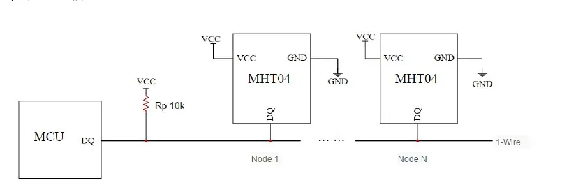
The DQ pin is connected to the MCU GPIO and pulled up to VCC via Rp. For short-distance board-level connections, a pull-up resistance in the range of 4.7kΩ to 10kΩ can be tested for adaptation; for long-distance or multi-node scenarios, the pull-up resistance should be reduced according to voltage, bus capacitance and timing requirements, followed by on-site verification. The long-distance example provided in the product datasheet specifies a 5V supply with a 1kΩ pull-up resistor.
I²C connection
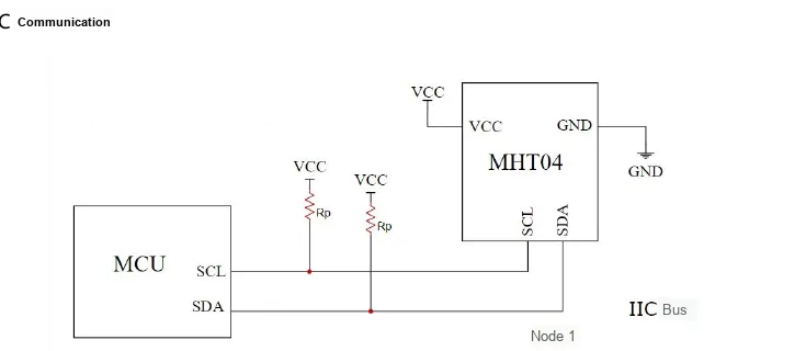
SDA and SCL are connected to the corresponding ports of the MCU respectively and pulled up to VCC. The pull-up resistance depends on the power supply, capacitance and bus rate; for short traces on the board, a starting value of 4.7kΩ is generally applicable, and for long traces, direct expansion in accordance with the standard board-level I²C method is not recommended.
2.6 Chip Configuration
- I²C slave 7-bit address: 0x44.
- Temperature + Capacitance Channel 1 Conversion Completion Time: It is recommended to wait for at least 30ms before reading the latest data.
- CRC-8: The initial value of the sample code is 0xFF, and the polynomial is expressed as 0x131 (the lower 8 bits 0x31 are used in calculation).
- Capacitance conversion requires Co (center/bias capacitance) and Cr (capacitance range); in the I²C data stream, the typical value of Cr is 15.492 pF, and Co can be configured within the range of 0 to 103.5 pF.
- The humidity coefficients HumA and HumB are unsigned numbers: HumA = raw/100.0, HumB = raw/10.0.
Calibration Data Protection: Do not copy the HumA/HumB and Co/Cr configurations of one module to another. After replacing the sensor, re-read the parameters stored in the device's own EEPROM.
2.7 Communication Interfaces and Related Protocols
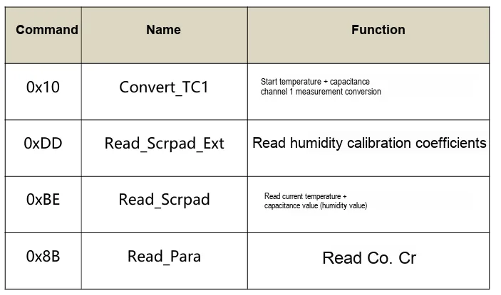
1-Wire Bus Command
I²C Commands and Read Timing
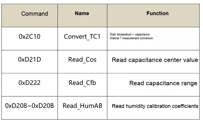
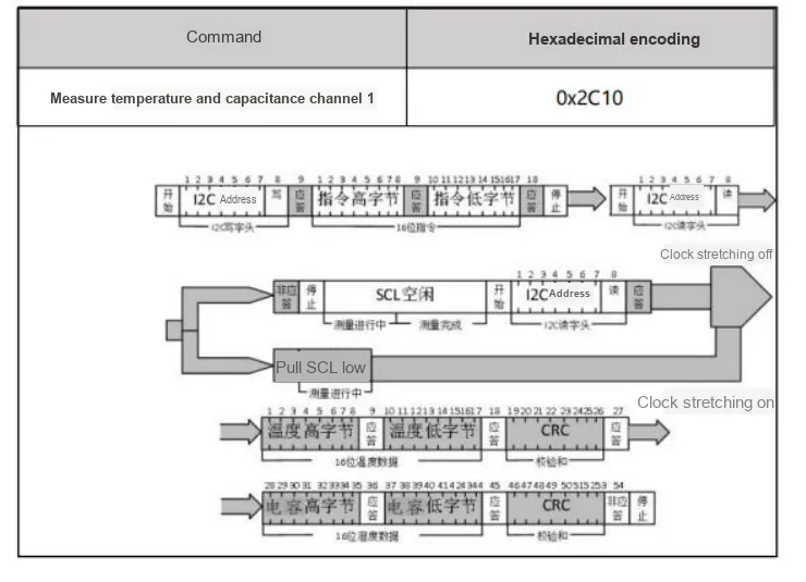
After sending 0x2C10, the device performs conversions for the temperature and capacitance channel 1. Wait for at least 30ms and then directly read 6 bytes: Temp_H, Temp_L, CRC, Cap_H, Cap_L, CRC. The main controller shall verify the CRC of each of the two 2-byte data blocks separately.
2.8 Register Definition
Location/Block | Byte Definition | Conversion or Application |
|---|---|---|
Conversion Result 0~2 | Temp_H, Temp_L, CRC | T = signed16(raw)/256 + 40℃ |
Conversion Result 3~5 | Cap_H, Cap_L, CRC | CD = (Cap_H<<8)|Cap_L |
0xD208~0xD20B | HumA_H, HumA_L, HumB_H, HumB_L | Humidity Slope/Offset Coefficient |
0xD21D | Cos | Capacitor Center/Bias Configuration |
0xD222 | Cfb | Capacitance Range Configuration |
Core Conversion Formula
Temperature: T = signed16((Temp_H<<8)|Temp_L) / 256.0 + 40.0 (℃)
Capacitance: Cx = 2 × (CD/(2^16-1) - 1/2) × Cr + Co, where CD = (Cap_H<<8)|Cap_L.
Humidity: RH =(HumA_raw/100.0) × Cx -(HumB_raw/10.0).
Temperature compensation: RH = RH - 0.2 ×(30.0 - Temp). Finally, limit RH to the range of 0~100%.
Implement reminder: the original temperature value is a signed 16-bit integer, and the humidity coefficient is an unsigned 16-bit integer. Byte order, sign extension and CRC are the most common sources of porting errors.
III. Circuit Engineering
3.1 Circuit Source Engineering
To obtain the source project of the circuit, please refer to the link below:
https://mysentech.com/productinfo/506263.html
3.2 Module Usage Instructions
3.2.1 Hardware Access and Power-on Check- Check the device version: the 1-Wire version and the I²C version have different interfaces; the I²C address is fixed at 0x44.
- Keep VCC within the range of 2.0V to 5.5V, place the power supply bypass capacitor close to the module, and make the ground loop as short as possible.
- Keep the humidity-sensitive probe clean and well-ventilated; do not scrub it, touch it with hands, seal it with adhesive, or leave it covered by condensed water for a long time.
- First verify the original temperature, capacitance and CRC, then introduce the HumA/HumB humidity conversion to facilitate layered problem locating.
- In environments with high humidity, salt spray, condensation, or chemical gases, MHT04H shall be preferentially selected and verified via complete machine structural protection.
- Scan or access 0x44 to confirm the ACK;
- Read Co/Cr and HumA/HumB, and check that the data is not all zeros or all 0xFF;
- Send 0x2C10 and wait for 30ms;
- Read the 6-byte conversion result and verify the two CRCs respectively;
- Convert temperature, capacitance and relative humidity, and perform temperature compensation and amplitude limiting;
- Compare with a reliable temperature and humidity reference instrument at multiple points to confirm the system error and response time.
3.2.2 Usage of Modbus Poll
Modbus Poll is a universal Modbus master debugging tool compatible with all capacitive sensors in this series that support the Modbus-RTU protocol. It enables quick serial communication debugging, real-time data reading and log export between sensors and computers, serving as a universal host computer tool for verifying sensor functions and collecting test data. The software supports Modbus RTU/ASCII/TCP/IP protocols, is compatible with multiple register types and data formats, and its operation process is universal for the entire series of sensors.
Before use, you need to complete the software installation and activation first. You can download the installation package through official channels; the first launch supports a 30-day trial, and you can also enter a registration code for permanent activation. After the hardware connects the sensor to the computer, open the software and click "Connection" - "Connect", then configure the serial port parameters (Port Number, baud rate, data bit/parity bit/stop bit; this series of sensors defaults to the 9600 Baud, 8N1 format, subject to the specification sheet of the corresponding specific model) in the pop-up window, and confirm to establish a communication connection.
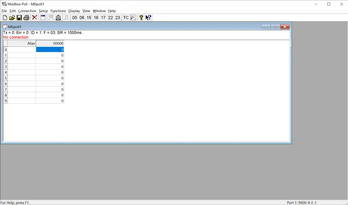
The following is a description of the general operation process:
- Serial Port Connection Configuration: After connecting the sensor to the computer via a USB-to-serial port module, launch the Modbus Poll software, click "Connection" - "Connect" on the menu bar, select the COM Port Number corresponding to the sensor in the pop-up window, and configure the serial port parameters matching the sensor (baud rate, data bits, parity check mode, stop bits; this series of sensors defaults to 9600 Baud, 8N1 format), then confirm to establish a communication connection.
- Import Sensor Configuration File: The software supports importing
. mbppre-configuration files corresponding to various sensor models. These files come with preset register addresses, data formats, and alias definitions, eliminating the need for manual register configuration. Simply open the. mbpfile for the corresponding sensor in the software to automatically load all parameters. Once the connection is established, real-time detection data of the sensor (such as dust/rain/frost thickness values, status flag bits, etc.) will be displayed directly. - Data Logging (Optional): If you need to save test data, you can configure logging rules via the "Setup" - "Excel Log" function. It supports logging data at fixed intervals or with every data update, and allows you to set a maximum number of log entries, facilitating subsequent analysis and verification of sensor data.
3.3 Application Experiment
Here, we use the GraftPort-RP2040 development board for testing, and the MHT04 temperature and humidity sensor uses the I2C interface to communicate with the main controller.
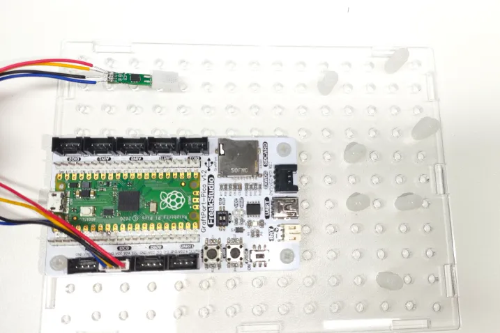
This diagram illustrates the I2C wiring between the MHT04 module and the GraftPort-RP2040 development board.
The module connections are shown in the following table:
Development Board Pins | Module Pins | Description |
Pin 4 |
|
|
Pin 5 |
|
|
Here, we need to search for the relevant driver packages on uPyPI: https://upypi.net/zh/

This diagram demonstrates the process of searching for the WS61 driver package in uPyPI.
Enter mht04iic_driver to search, and the following will be displayed:

This diagram shows the mht04iic_driver search results, which are used to confirm the corresponding driver package.
Click to copy the local installation command:
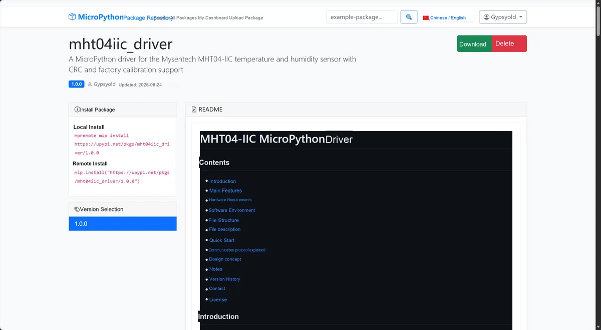
This diagram shows the interface for copying the WS61 driver installation command, to facilitate the completion of environment preparation.
Import the module driver library code via the mip tool. Below are the usage commands for the mpremote tool:
mpremote mip install https://upypi.net/pkgs/mht04iic_driver/1.0.0After importing, copy the following main.py code into our project:
# Python env   : MicroPython v1.23.0
# -*- coding: utf-8 -*-
# @Time    : 2026/08/21 16:44
# @Author  : December
# @File    : main.py
# @Description : Test driver for the MHT04-IIC temperature and humidity sensor from Sensor Source
# @License : MIT

# ======================================== Import Modules =========================================

import time
from machine import I2C, Pin
from mht04 import MHT04, MHT04Error

# ======================================== Global Variables ============================================

I2C_ID = 0
SDA_PIN = 4
SCL_PIN = 5
I2C_FREQUENCY = 100000
DEVICE_ADDRESS = 0x44
PRINT_INTERVAL_MS = 1000

# ======================================== Functions ============================================

def scan_i2c(i2c: I2C) -> int:
    """Scan the I2C bus and return the MHT04-IIC address."""
    # Wrap the call in a single-element tuple, compatible with MicroPython and satisfying the repository's instance position check rule.
    devices = (getattr(i2c, "scan")(),)[0]
    if not devices:
        raise RuntimeError("No I2C device found")

    print("I2C devices: %s" % ["0x%02X" % address for address in devices])
    if DEVICE_ADDRESS not in devices:
        raise RuntimeError("Device not found at expected address")
    return DEVICE_ADDRESS

def test_basic_read(sensor: MHT04) -> None:
    """Read and print the temperature and relative humidity once."""
    temperature, humidity = (getattr(sensor, "read")(),)[0]
    print("Temperature: %.2f C, Humidity: %.2f %%RH" % (temperature, humidity))

# ======================================== Custom Classes ============================================

# ======================================== Initialization ==========================================

time.sleep(3)
print("FreakStudio: Using Mysentech MHT04-IIC sensor ...")

# On the RP2040 Pico, use I2C0, with GP4 as SDA and GP5 as SCL
i2c = I2C(
    I2C_ID,
    sda=Pin(SDA_PIN),
    scl=Pin(SCL_PIN),
    freq=I2C_FREQUENCY,
)

# This device has no fixed ID register; verify the response using an address scan and a calibration parameter read
driver_address = scan_i2c(i2c)
sensor = MHT04(i2c=i2c, address=driver_address)
configuration = sensor.refresh_configuration()
print("MHT04 configuration: %s" % configuration)

last_print_time = time.ticks_ms()

# ========================================  Main Program  ===========================================

try:
    while True:
        current_time = time.ticks_ms()
        if time.ticks_diff(current_time, last_print_time) >= PRINT_INTERVAL_MS:
            test_basic_read(sensor)
            last_print_time = current_time
        time.sleep_ms(10)

except KeyboardInterrupt:
    print("Program interrupted by user")
except OSError as error:
    print("Hardware communication error: %s" % error)
except MHT04Error as error:
    print("MHT04 driver error: %s" % error)
except Exception as error:
    print("Unknown error: %s" % error)
finally:
    print("Cleaning up resources...")
    sensor.deinit()
    del sensor
    del i2c
    print("Program exited")
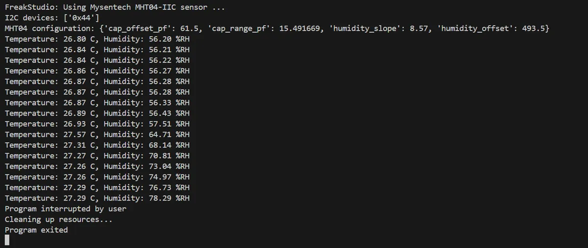
Burn the code, open the terminal, and the output is as follows:
This figure illustrates MHT04 the temperature and humidity information output by the sample program.
4. Drivers
function | Function | Porting Considerations |
MHT04_Read_Temp_Hum | Complete Temperature and Humidity Acquisition Process | It is recommended to add return values and output parameters |
MDC04_ConvertCapTemp | Starting Temperature + Capacitance Conversion | Send 0x2C10 |
ReadTempCap1 | Read the 6-byte conversion result | Segmented CRC Check, Byte Order |
Read_HumAB | Read 4-byte humidity coefficient | Address 0xD208~0xD20B |
MDC04_OutputtoTemp | Convert Original Temperature to Celsius | Signed 16-bit |
MDC04_OutputtoCap | Convert original capacitance to pF | Dependent on Co and Cr |
MY_I2C_CRC8 | CRC-8 Check | Initial value 0xFF, polynomial 0x31 |
5. BOM & Recommended Alternative Parts
The product manual does not provide the complete internal BOM of the module. The table below presents the minimum material recommendations for the system integration side, which does not represent the internal Bill of Material of MHT04 (H). Any replacement of the sensor body must undergo a re-evaluation of mechanical dimensions, interface protocols, calibration algorithms and environmental reliability.
Category | Recommended Materials/Specifications | Substitution and Notes |
Sensor | MHT04 / MHT04-IIC | Standard environment; interface versions are not interchangeable |
High-reliability sensor | MHT04H / MHT04H-IIC | Priority shall be given to environments with high humidity, salt spray and condensation |
Low-temperature version | MHT04H-LT Series | Low temperature requirement of -55℃, verification of the complete machine materials is required |
remote probe | MHT04T14 / MHT04HT14 | 14mm metal probe, customizable cable length |
pull-up resistor | 1kΩ~10kΩ, 1% | Select according to voltage, line length, number of nodes and bus capacitance |
Power supply decoupling | 0.1μF X7R | Place close to VCC/GND; parallel a 1μF capacitor if necessary |
Connectors/Cables | Select models according to environmental level | Prioritize shielding/twisting for long cables, and evaluate surge and ESD |
Principle of Substitution: If other temperature and humidity devices are used instead, the HumA/HumB conversion process of MHT04 or the conversion process of MDC04 cannot be reused; the driver, calibration and error budget need to be redesigned according to the protocol of the new device.
VI. Revision History
Document Version | Date of Revision | Modifier | Modify Content |
v1.0 | 2026-08-21 | Mi Ming Xuan | Initialize the document |
VII. Relevant Materials
MHT04+MHT04H Temperature and Humidity Sensor Product Manual-MSE202607.pdf 797 KB