
Contents
- Introduction
- I. Module Introduction
- II. Introduction to Major Chips
- 2.1 Chip Overview
- 2.2 Pin Definition
- 2.3 Functional Block Diagram
- 2.4 Performance Parameters
- 2.5 Reference Circuit
- 2.6 Chip Configuration
- 2.7 Communication Interfaces and Related Protocols
- 2.8 Register Definition
- III. Circuit Engineering
- 3.1 Circuit Source Engineering
- 3.2 Module Usage Instructions
- 3.3 Application Experiment
- 4. Drivers
- 5. BOM & Recommended Alternative Parts
- VI. Revision History
- VII. Relevant Materials
Introduction
In applications such as robot tactile sensing, medical healthcare, consumer electronics, and flexible weighing, the sensitivity, stability and response speed of pressure detection directly determine the device's ability to perceive external conditions and its control accuracy. However, traditional mechanical switches, rigid weighing components and common resistive thin-film pressure sensors generally suffer from drawbacks including "difficulty in continuous measurement, limited structural adaptability, and significant hysteresis and drift": mechanical switches can usually only detect whether they are pressed or released, and cannot reflect the changing process of pressure; rigid weighing components are relatively bulky, making them hard to install on robot fingertips, curved surfaces or narrow spaces;Some resistive flexible sensors are susceptible to the influences of material hysteresis, temperature and mounting structure, which brings difficulties to precise measurement and repeated calibration.

The MFYM-1S-9-9 single-point flexible pressure development board is an integrated pressure sensing solution designed specifically to address these issues. The module adopts a hybrid capacitive technology combining novel pressure-sensitive materials and PCB, and works with the MCP1081 capacitive acquisition chip to convert pressure changes exerted on the flexible sensing sheet into continuous capacitive data, which is directly output via the UART interface. Compared with mechanical switches that can only provide on-off signals, it can continuously reflect pressure changes; compared with bulky rigid force-measuring structures, it features a compact size, concentrated sensing area, and easy embedment;Compared with traditional flexible pressure solutions that are prone to significant hysteresis and drift, it features high sensitivity, good linearity, low drift, low hysteresis and fast response and other advantages.
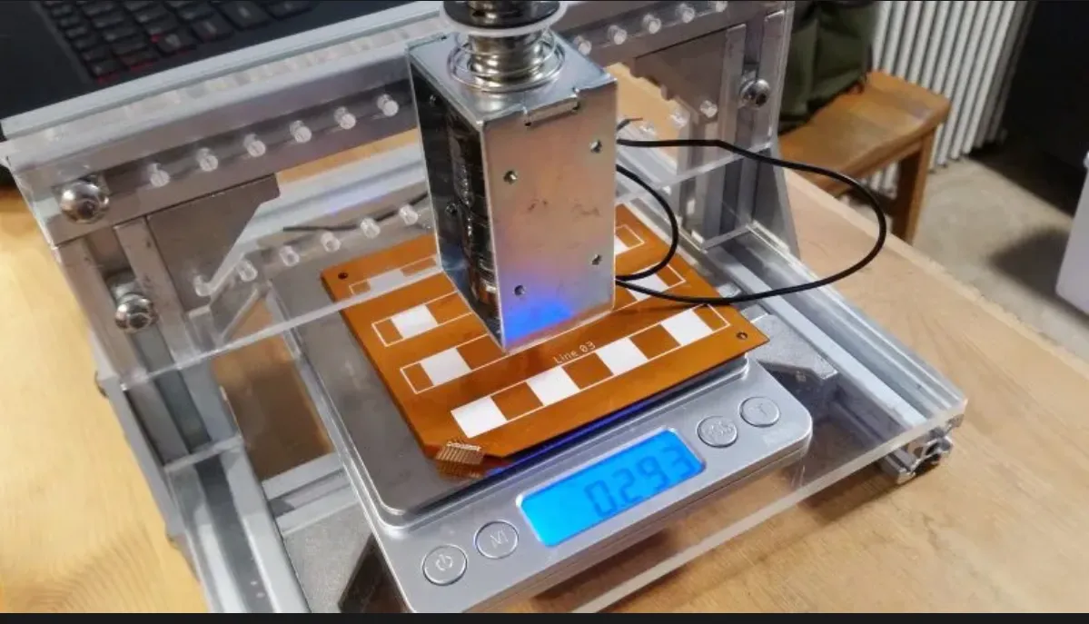
The nominal detection range of MFYM-1S-9-9 is 0~100 kPa, with a detection sensitivity of less than 10 Pa, a response time of less than 5 ms, a linearity of R²>0.98, a signal drift of less than 1%, and a service life of over 3 million cycles.The module features a 115200 baud UART digital output, allowing the application side to directly acquire data from the pressure-sensitive channel, reference channel, compensation channel and temperature channel. This facilitates zero-setting under no-load conditions, temperature analysis, pressure calibration and upper-layer algorithm development, providing a compact and easily integrated solution for machine tactile sensing and precise pressure measurement.
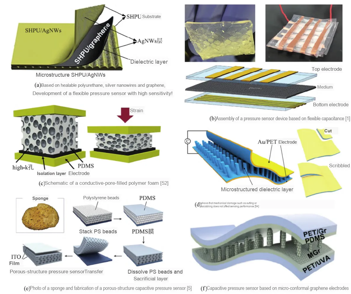
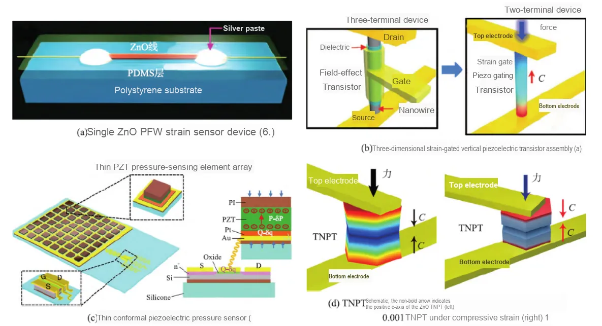
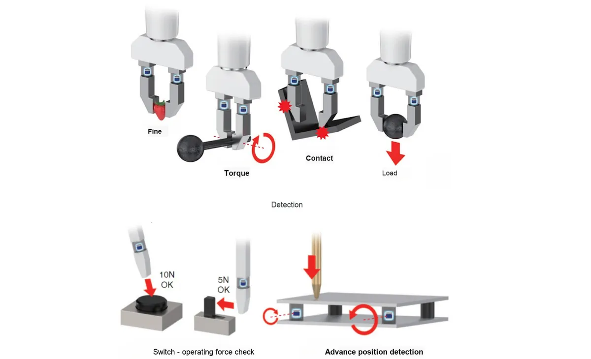
In humanoid robot and industrial robot scenarios, the MFYM-1S-9-9 can be mounted on the fingertips of robotic hands, the contact surfaces of grippers, the soles of feet, or other positions where contact force sensing is required. When a robot grasps an object, this module can continuously detect the contact pressure and its changing trend, providing basic data for grasping force adjustment, contact state judgment, and sliding trend identification.Its miniaturized structure is suitable for being embedded into the end of robots with limited installation space, and after multi-point combination, it can also form a distributed tactile sensing area, helping robots more delicately perceive the contact position and force changes of objects, and reducing the risk of slippage caused by insufficient clamping as well as object damage caused by excessive pressure.
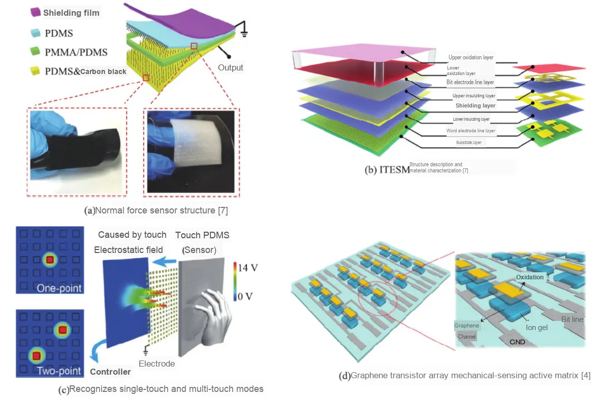
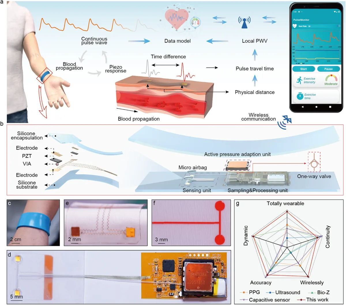
In medical healthcare and smart wearable scenarios, the MFYM-1S-9-9 can be used for signal acquisition in prototypes of pulse wave, heart rate, pressure change and blood pressure measurement. The flexible sensitive patch can be integrated with skin contact surfaces, wristbands or other flexible structures to detect tiny periodic pressure changes; its high sensitivity and fast response capability help preserve the details in pressure waveforms, and the UART digital output also facilitates the main controller to perform filtering, feature extraction and data logging.It should be noted that when the module is used in medical and health products, it shall be recalibrated according to the final contact structure, wearing pressure and operating temperature, and complete the corresponding verification of safety, accuracy and medical regulations.
In consumer electronics and human-computer interaction scenarios, the MFYM-1S-9-9 can be applied to pressure buttons, sliding detection, smart homes, virtual reality devices, and household appliances. Compared with conventional mechanical buttons, continuous pressure data can not only identify whether a button is pressed, but also further distinguish between light touch, heavy press and sustained press, thus providing richer interaction modes for devices; after arranging multiple sensing points along the operation area, it can also judge finger movement and pressure distribution changes in combination with algorithms.In flexible weighing and smart home applications, the module can also be installed under the load-bearing surface, and detect load changes through a well-designed contact head and base structure, providing a sensing basis for small-scale weighing, status judgment and object presence detection.
I. Module Introduction
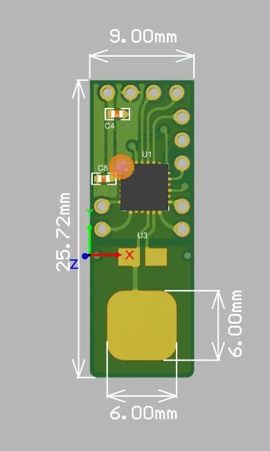
MFYM-1S-9-9 is a single-point flexible pressure sensing module featuring high sensitivity, excellent linearity, low drift and low hysteresis. The module consists of a flexible pressure-sensitive sheet, a PCB hybrid structure capacitive unit, and a MCP1081 capacitive acquisition and digital output circuit. The tested firmware actively outputs pressure-sensitive channel, reference/compensation channel and temperature data via UART ASCII data stream at a baud rate of 115200.
Project | Description |
Product Model | MFYM-1S-9-9 |
Product Form | Single-point flexible pressure development board/sensor module |
Core Technology | Capacitor Technology Based on Hybrid Structure of Pressure-Sensitive Material and PCB |
acquisition chip | MCP1081 (as per the product brief) |
Output Interface | UART, 115200 baud, 8N1 |
Typical Applications | robot tactile perception, medical healthcare, pressure keypad, sliding detection, automotive electronics, smart home, virtual reality, flexible weighing |
II. Introduction to Major Chips
2.1 Chip Overview
The product specification explicitly states that this module is designed to work with the MCP1081 capacitive acquisition chip. In this module, the chip serves core functions in flexible pressure capacitive signal acquisition, reference/compensation channel processing, and the digital output chain. Since no standalone datasheet for the MCP1081 is available in the current documentation, this section only describes the system behavior confirmed by product materials and measured UART data, and does not elaborate on unvalidated internal parameters of the chip.
2.2 Pin Definition
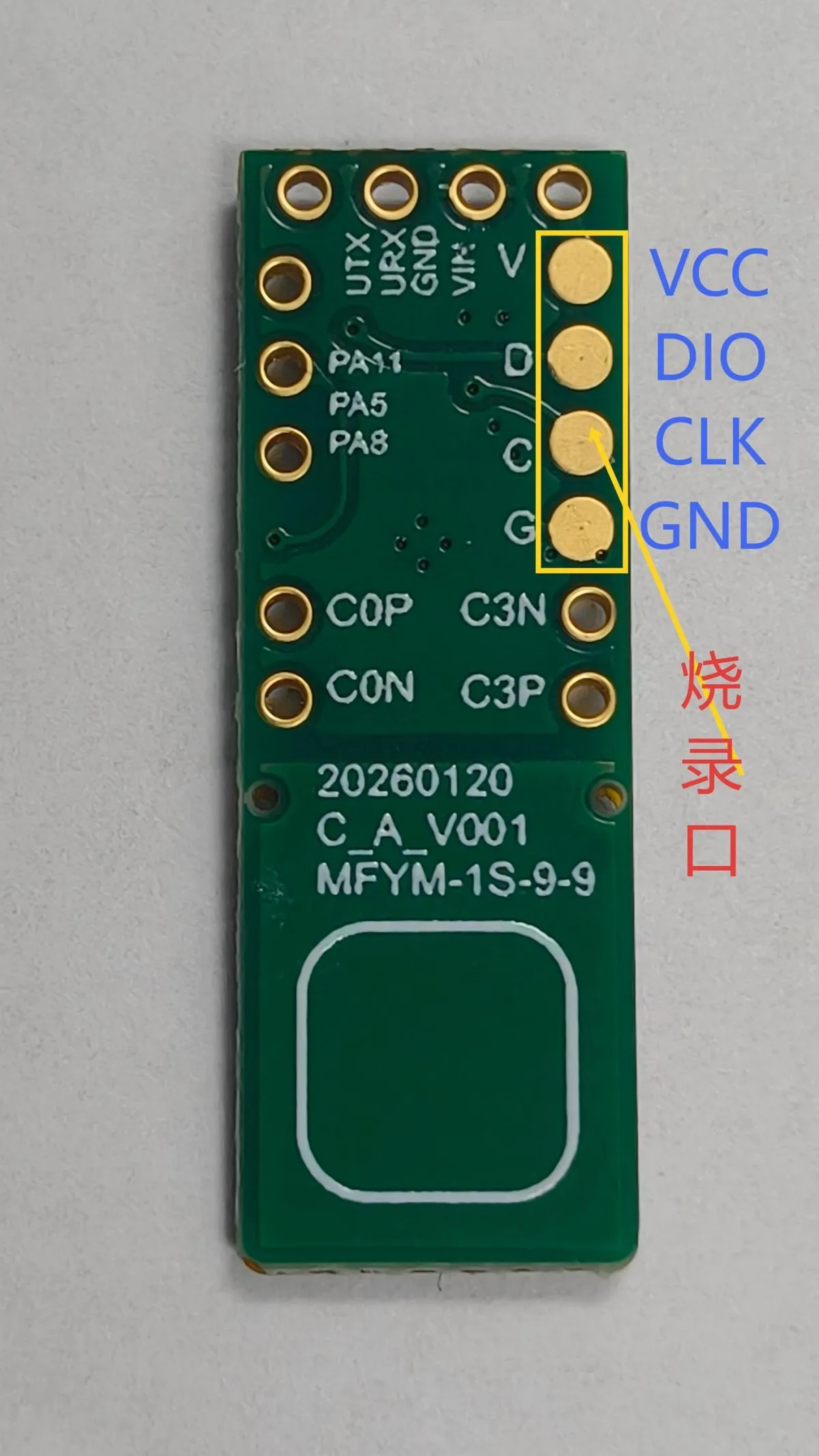
The common application interface is 4-wire UART. TXD/RXD shall be cross-connected with the main controller and ensure common ground at both ends. The product image also shows DIO/CLK/GND/VCC programming/debugging pads; this interface does not belong to the daily Data Acquisition interface, its operation protocol is not provided in the documentation, and the application side shall not drive it directly.
Module Pins | Direction (relative to the module) | Functions | Wiring Instructions |
VCC | Input | Power Supply | It is recommended to use 3.3 V power supply for the test materials first |
GND | - | Power Ground | Must share a common ground with the main controller |
RXD | Input | UART Reception | Connect the main control UART TX |
TXD | Output | UART Transmission | Connect to the main control UART RX |
2.3 Functional Block Diagram
The module can be understood according to the following signal chain:
Pressure Input | Sensing Conversion | Acquisition and Compensation | Digital Output |
Flexible sheet under force: | Pressure-Sensitive Materials and Capacitance Variation of Hybrid Structures | MCP1081 collects S/R/C0/C3 and provides temperature fields | UART ASCII data stream |
where S is the pressure-sensitive channel; R, C0, and C3 are reference/compensation-related channels; and T is the temperature field. Applications typically perform zeroing and pressure conversion on S, while retaining the other fields for diagnostic and compensation analysis.
2.4 Performance Parameters
Parameters | nominal value | Description |
Detection Range | 0~100 kPa | Product Introduction: Nominal Range |
Detection Sensitivity | <10 Pa | Product Introduction Nominal Value |
Response Time | <5 ms | Product Introduction Nominal Value |
Sensitivity | 0.36 kPa⁻¹ | Nominal relative sensitivity for quick conversion |
signal drift | <1% | Product Introduction Nominal Value |
Linearity | R²>0.98 | Product Introduction Nominal Value |
service life | >3 million times | Product Introduction Nominal Value |
Operating Temperature | -20℃~+85℃ | Product Introduction Nominal Range |
Operating Humidity | 0~100%RH | Product Introduction Nominal Range |
Output Mode | UART | Active ASCII Data Stream |
Baud Rate | 115200 | 8 data bits, no parity, 1 stop bit |
Note: The performance parameters are obtained at room temperature under the manufacturer's test conditions. The shape of the contact tip, force-bearing area, preload, base stiffness, assembly tolerance and temperature will all affect the system-level results; for accurate measurement, recalibration shall be performed in the final installed structure.
2.5 Reference Circuit
Taking Raspberry Pi Pico / RP2040 as an example, UART0 can be used for quick verification. The power supply voltage shall be subject to the actual hardware specifications and the confirmation information from the manufacturer; the existing test materials recommend using 3.3 V for power supply first.
Raspberry Pi Pico | MFYM-1S-9-9 | Function |
3V3(OUT) | VCC | Module Power Supply |
GND | GND | common reference ground |
GP16 / UART0 TX | RXD | Main control sends to the module |
GP17 / UART0 RX | TXD | Main control receives module data |
Wiring Notes: TX/RX must be cross-connected; do not connect Pico's VBUS or VSYS to the UART signal pins; check the power supply and ground before powering on, and run the original serial port monitoring program first during the initial joint debugging to confirm the data format.
2.6 Chip Configuration
The currently available measured firmware actively outputs data after power-on, and there is no need for the main controller to write registers to initiate acquisition. The application side mainly configures UART, field selection and pressure calibration parameters:
Configuration Item | Recommended/Default Value | Applications |
UART | 115200, 8N1 | Serial Communication Parameters |
value_key | s | Select the pressure-sensitive field S |
timeout_ms | 2000 | Read timeout |
sensitivity | 0.36 | Nominal relative sensitivity, unit: kPa⁻¹ |
polarity | 1 or -1 | Adapt to the situation where the original value rises or falls after pressurization |
No-load zero setting | Discard 5 frames, 7-frame median | Suppress start-up transients and accidental fluctuations |
Two-point Calibration | No-load point + known pressure point | Linear Calibration under the Final Mechanical Structure |
P = polarity × (S / S_zero - 1) / 0.36

When two-point calibration takes priority: P = slope × S + offset
2.7 Communication Interfaces and Related Protocols
The tested module actively outputs readable ASCII lines via UART. Frames containing only spaces may appear between valid data, which will be automatically ignored by the driver. A typical valid frame is as follows:
S:1627 pF,R:2000 pF,C0:1020 pF,C3:987 pF;T:2813 C\r\nField | Example | Meaning | Application Recommendations |
S | 1627 pF | pressure-sensitive channel | Default for zero reset and pressure conversion |
R | 2000 pF | Reference Value | Reserved for diagnostics |
C0/C3 | 1020/987 pF | Compensation/Reference Capacitance Channel | Reserved for compensation analysis |
T | 2813 C | 100 times the temperature | 2813 stands for 28.13℃ |
- Delimiter: Commas are mainly used between fields, and semicolons are also treated as delimiters;
- Field format: name, colon, value and unit; the driver is compatible with KEY= VALUE, CSV and pure numeric lines at the same time;
- Frame boundary: ends with a newline character; the receiving end shall maintain a buffer and handle partial frames, frame sticking and timeout cases;
- The currently measured protocol is not Modbus RTU, so umodbus is not required.
2.8 Register Definition
The currently provided product introductions, measured data and driver materials all indicate that the application interface adopts an active UART ASCII data stream, and no register table available for read and write by the main controller is provided. Therefore, this model is not applicable to the Modbus register definition under the current firmware. If the subsequent firmware is changed to a binary or register protocol, the official protocol document corresponding to the firmware version shall prevail, and the frame structure, byte order, check mode and field proportion shall be rechecked.
III. Circuit Engineering
3.1 Circuit Source Engineering
To obtain the source project of the circuit, please refer to the link below:
https://mysentech.com/productinfo/231905.html
3.2 Module Usage Instructions
3.2.1 Test Environment Setup and Precautions
- Keep the sensitive area unloaded, and complete the wiring according to 3.3 V, GND and cross TX/RX.
- First run uart_monitor.py to confirm that complete ASCII data lines are continuously received in the terminal.
- Load the driver and the sample program, discard 5 frames after startup, and collect the median of 7 frames to complete no-load zeroing.
- Gently press the sensitive area and observe whether the S field and the converted pressure change stably with the load. If the change directions are opposite, set the polarity to -1.
- After completing the mechanical installation, perform two-point calibration with standard load, and verify the full-scale linearity, zero return, hysteresis and temperature drift.
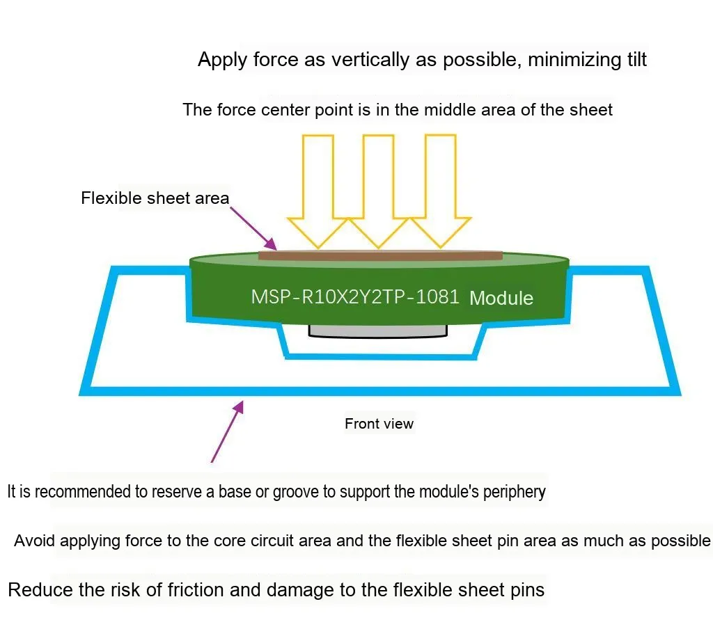
Key Notes: The force application center shall be located at the center of the silk-screen sensitive area of the back circular frame; apply force as vertically and evenly as possible; reserve a base or groove for peripheral support of the module, and avoid the core circuit and the pin area of the flexible sheet; prevent sharp objects from puncturing, rubbing or causing eccentric load.
3.2.2 Usage of Modbus Poll
Modbus Poll is a universal Modbus master debugging tool compatible with all capacitive sensors in this series that support the Modbus-RTU protocol. It enables quick serial communication debugging, real-time data reading and log export between sensors and computers, serving as a universal host computer tool for verifying sensor functions and collecting test data. The software supports Modbus RTU/ASCII/TCP/IP protocols, is compatible with multiple register types and data formats, and its operation process is universal for the entire series of sensors.
Before use, you need to complete the software installation and activation first. You can download the installation package through official channels; the first launch supports a 30-day trial, and you can also enter a registration code for permanent activation. After the hardware connects the sensor to the computer, open the software and click "Connection" - "Connect", then configure the serial port parameters (Port Number, baud rate, data bit/parity bit/stop bit; this series of sensors defaults to the 9600 Baud, 8N1 format, subject to the specification sheet of the corresponding specific model) in the pop-up window, and confirm to establish a communication connection.
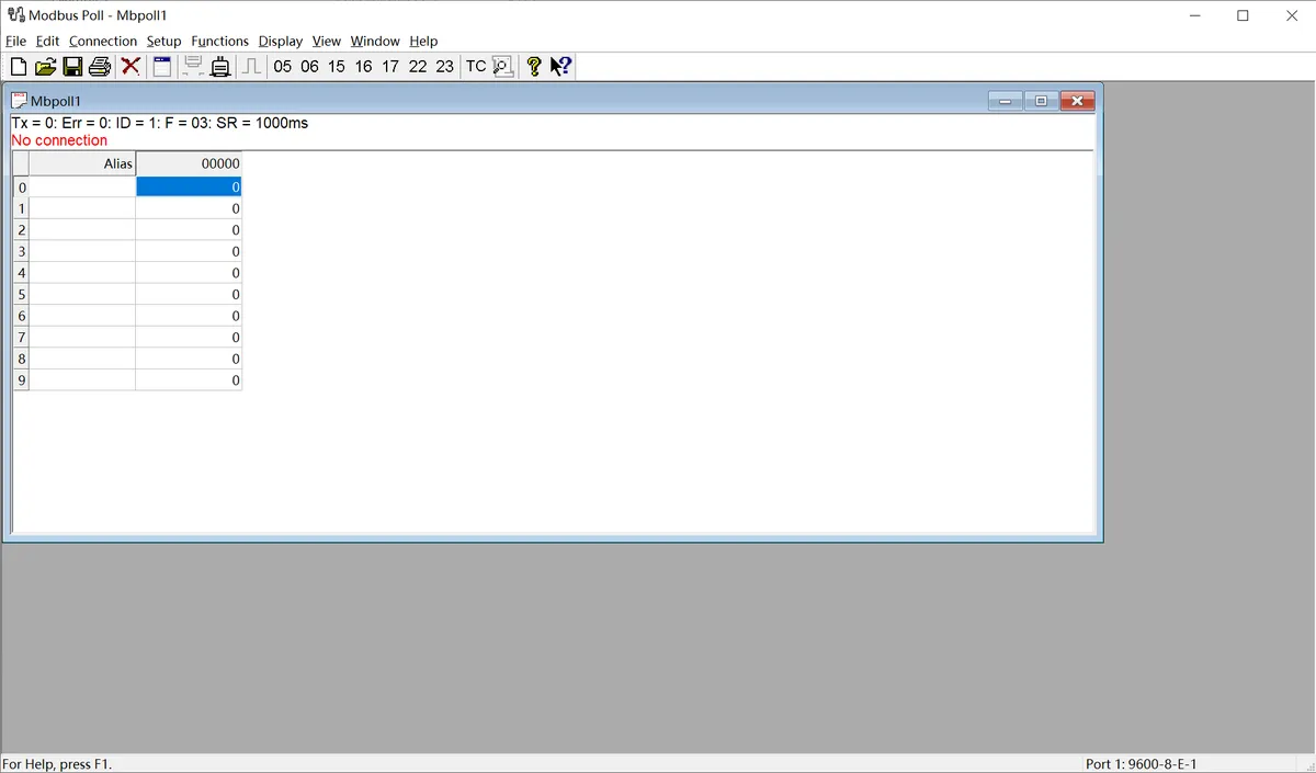
The following is a description of the general operation process:
- Serial Port Connection Configuration: After connecting the sensor to the computer via a USB-to-serial port module, launch the Modbus Poll software, click "Connection" - "Connect" on the menu bar, select the COM Port Number corresponding to the sensor in the pop-up window, and configure the serial port parameters matching the sensor (baud rate, data bits, parity check mode, stop bits; this series of sensors defaults to 9600 Baud, 8N1 format), then confirm to establish a communication connection.
- Import Sensor Configuration File: The software supports importing
. mbppre-configuration files corresponding to various sensor models. These files come with preset register addresses, data formats, and alias definitions, eliminating the need for manual register configuration. Simply open the. mbpfile for the corresponding sensor in the software to automatically load all parameters. Once the connection is established, real-time detection data of the sensor (such as dust/rain/frost thickness values, status flag bits, etc.) will be displayed directly. - Data Logging (Optional): If you need to save test data, you can configure logging rules via the "Setup" - "Excel Log" function. It supports logging data at fixed intervals or with every data update, and allows you to set a maximum number of log entries, facilitating subsequent analysis and verification of sensor data.
3.3 Application Experiment
Here, we use the GraftPort-RP2040 development board for testing, and the MFYM-1S-9-9 uses the UART interface to communicate with the main controller.
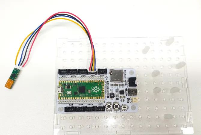
This diagram illustrates the UART wiring method between the WS61 module and GraftPort-RP2040 development board.
The module connections are shown in the following table:
Development Board Pins | Module Pins | Description |
Pin 16 |
|
|
Pin 17 |
|
|
Here, we need to search for the relevant driver packages on uPyPI: https://upypi.net/zh/
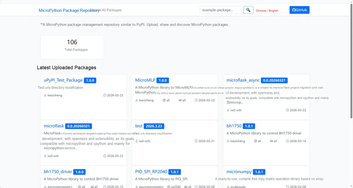
This diagram demonstrates the process of searching for the WS61 driver package in uPyPI.
Enter mfym1s99_driver to search, and the following will be displayed:
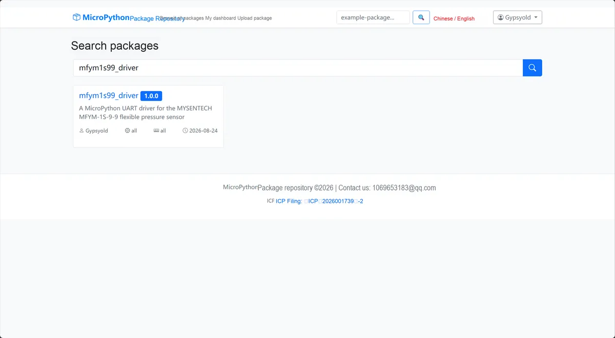
This diagram illustrates the search results for mfym1s99_driver, which are used to confirm the corresponding driver package.
Click to copy the local installation command:
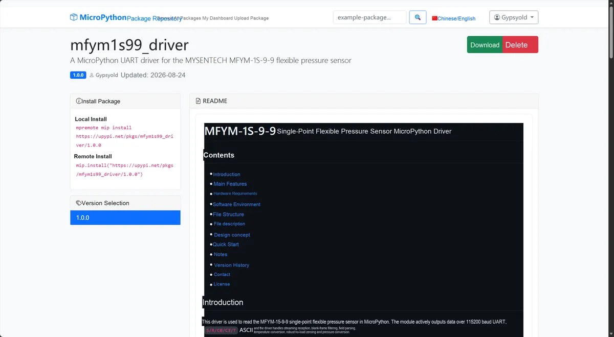
This diagram shows the interface for copying the WS61 driver installation command, to facilitate the completion of environment preparation.
Import the module driver library code via the mip tool. Below are the usage commands for the mpremote tool:
mpremote mip install https://upypi.net/pkgs/mfym1s99_driver/1.0.0After importing, copy the following main.py code into our project:
# Python env   : MicroPython v1.23.0
# -*- coding: utf-8 -*-
# @Time    : 2026/08/21 16:30
# @Author  : December
# @File    : main.py
# @Description : MFYM-1S-9-9 single-point flexible pressure sensor test program
# @License : MIT

# ======================================== Import Modules =========================================

import time
from machine import Pin, UART

from mfym1s99 import MFYM1S99

# ======================================== Global Variables ============================================

UART_ID = 0
UART_TX_PIN = 16
UART_RX_PIN = 17
UART_BAUDRATE = 115200
UART_TIMEOUT_MS = 2000
ZERO_DISCARD_SAMPLES = 5
ZERO_MEDIAN_SAMPLES = 7
LOOP_DELAY_MS = 100

# ======================================== Functions ============================================

# ======================================== Custom Classes ============================================

# ======================================== Initialization configuration ===========================================

# Wait for the Pico and the sensor to power up and stabilize.
time.sleep(3)
print("FreakStudio: MFYM-1S-9-9 Pressure Sensor Initialization")

# The UART hardware resource is created by the application, then injected into the driver.
uart = UART(
    UART_ID,
    baudrate=UART_BAUDRATE,
    bits=8,
    parity=None,
    stop=1,
    tx=Pin(UART_TX_PIN),
    rx=Pin(UART_RX_PIN),
    timeout=UART_TIMEOUT_MS,
    timeout_char=20,
    rxbuf=512,
)
sensor = MFYM1S99(
    uart=uart,
    value_key="s",
    timeout_ms=UART_TIMEOUT_MS,
)

print("Keep the sensing area unloaded while zeroing...")
print("Discarding 5 startup frames, then taking the median of 7 frames.")

# ========================================  Main Program  ============================================

try:
    sensor.clear()
    print("UART buffer ready; collecting zero samples...")
    baseline = sensor.zero(
        samples=ZERO_MEDIAN_SAMPLES,
        discard=ZERO_DISCARD_SAMPLES,
    )
    print("Zero raw: %.3f" % baseline)

    while True:
        sample = sensor.read_sample()
        if sample is None:
            print("UART timeout")
            continue

        # Extract the pressure channel, reference channel and temperature, then output them together.
        s_pf = sensor.sample_value(sample)
        pressure_kpa = sensor.pressure_from_raw(s_pf)
        r_pf = sensor.field(sample, "r", 0.0)
        c0_pf = sensor.field(sample, "c0", 0.0)
        c3_pf = sensor.field(sample, "c3", 0.0)
        temperature = sensor.temperature_c(sample)

        if temperature is None:
            print("S=%.0f pF  pressure=%.3f kPa" % (s_pf, pressure_kpa))
        else:
            print(
                "S=%.0f pF  R=%.0f pF  C0=%.0f pF  C3=%.0f pF  "
                "T=%.2f C  pressure=%.3f kPa"
                % (s_pf, r_pf, c0_pf, c3_pf, temperature, pressure_kpa)
            )
        time.sleep_ms(LOOP_DELAY_MS)

except KeyboardInterrupt:
    print("Program interrupted by user")
except OSError as error:
    print("Hardware communication error: %s" % str(error))
except Exception as error:
    print("Unknown error: %s" % str(error))
finally:
    print("Cleaning up resources...")
    sensor.deinit()
    uart.deinit()
    del sensor
    del uart
    print("Program exited")
Burn the code, open the terminal, and the output is as follows:
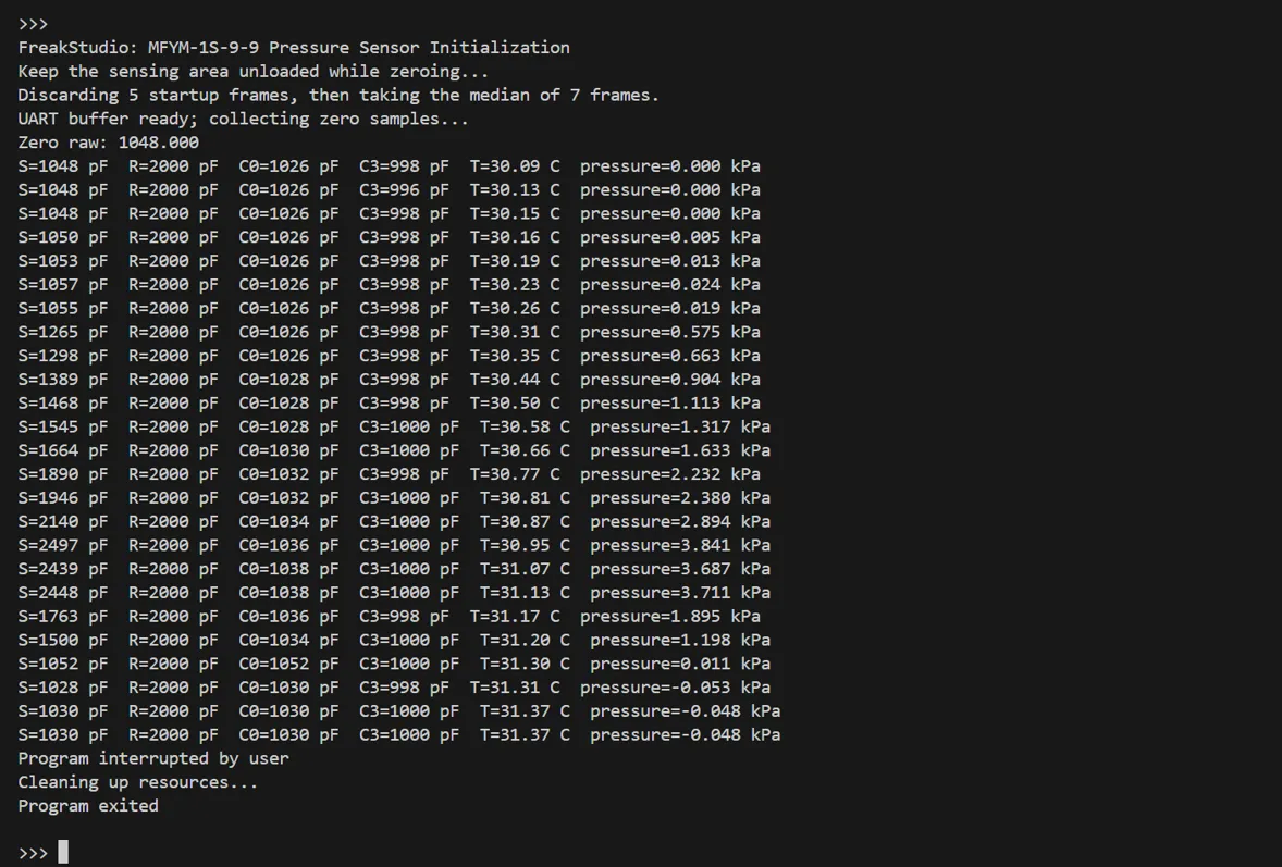
shows the pressure information and capacitive pressure information
4. Drivers
(Will be added to the official driver after subsequent code review and approval)
5. BOM & Recommended Alternative Parts
Materials | Recommended Specifications | Substitution Principle |
MFYM-1S-9-9 | Target Sensing Module | Core component, no verified direct substitute available |
Main Control Development Board | Raspberry Pi Pico or an MCU with a 3.3 V UART | Support 115200 baud rate, 8N1 configuration |
connecting wire | 4 short wires | Ensure reliable contact and reduce interference |
Force Contact Tip | Smooth, free of sharp edges, and dimensionally compatible with the sensitive area | Recalibration after material and area changes |
Mechanical base | Peripheral support and avoidance of the core circuit | Recalibration after changes in stiffness and preload |
Standard Load/Pressure Source | Cover the target range | For two-point or multi-point calibration after installation |
VI. Revision History
Document Version | Date of Revision | Modifier | Modify Content |
v1.0 | 2026-08-21 | Mi Ming Xuan | Initialize the document |
VII. Relevant Materials
MFYM-1S-9-9 Single-Point Flexible Pressure Development Board Product Introduction-MSE202603.pdf 834 KB