
Contents
- Introduction
- I. Module Introduction
- II. Introduction to Major Chips
- 2.1 Chip Overview
- 2.2 Pin Definition
- 2.3 Functional Block Diagram
- 2.4 Performance Parameters
- 2.5 Reference Circuit
- 2.6 Chip Configuration
- 2.7 Communication Interfaces and Related Protocols
- 2.8 Register Definition
- III. Circuit Engineering
- 3.1 Circuit Source Engineering
- 3.2 Module Usage Instructions
- 3.3 Application Experiment
- 4. Drivers
- 5. BOM & Recommended Alternative Parts
- VI. Revision History
- VII. Relevant Materials
Introduction
Among cleaning devices such as robotic vacuums, floor washers, and carpet cleaners, the dry-wet state of water-absorbing materials including roller brushes, mop cloths, and carpets directly affects the cleaning effect, drying time, and user experience of the equipment. Overly wet materials are prone to dripping, odor, and mildew; insufficient drying will lead to bacterial growth and secondary pollution; excessively long drying time, in turn, increases energy consumption, noise, and the risk of material aging. However, the moisture distribution inside water-absorbing materials is usually uneven, and it is difficult to accurately judge their actual dry-wet level solely based on operating time, surface temperature, or manual touch.
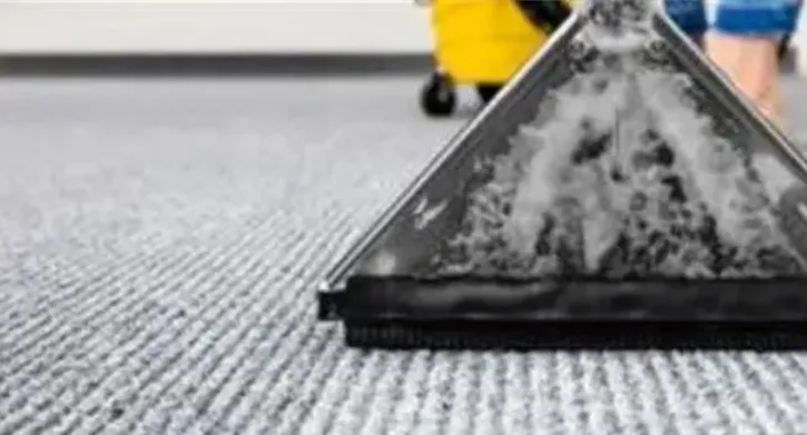
Traditional dryness and moisture determination methods all have their limitations: fixed-time drying cannot adapt to changes in material thickness, initial moisture content and ambient temperature; indirect calculation via motor load or temperature is susceptible to interference from friction, structural differences and environmental changes; contact electrodes, when exposed to humid and stained environments for a long time, may suffer from corrosion, contamination and data drift; ordinary air humidity sensors measure the relative humidity of the surrounding air, which cannot directly reflect the moisture changes inside materials such as roller brushes and mop cloths.HDS adopts a capacitive non-contact detection solution, which can sense changes in the dielectric properties of materials through non-metallic media such as plastic, continuously output capacitive data, and provide a reliable basis for material moisture classification, trend judgment and drying control by combining differential reference, temperature compensation and software algorithms.
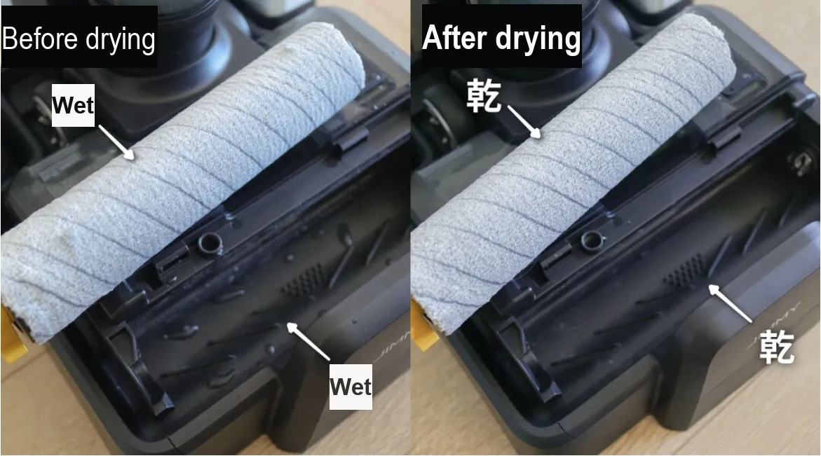
In the roller brush detection scenarios of robotic vacuums and floor washers, the HDS can be mounted on the inner side of the non-metallic housing near the roller brush. It leverages a flexible FPC structure to adapt to cylindrical curved surfaces, and senses the dry-wet changes of the roller brush without direct contact with sewage or bristles. The device can judge the change trend of the roller brush from wet to dry based on continuous capacitance data, and establish gear levels including dry, slightly wet, moderately wet, fairly wet, and wet in combination with calibration on actual prototypes, so as to provide data support for cleaning process monitoring, drying start-stop control, and abnormal status identification, and avoid insufficient drying or energy waste caused by fixed-time control.
It is recommended to draw a sectional view: the outer layer is a rolling brush, the middle is a plastic casing or air gap of 0~5 mm, and the inner side is attached with an HDS flexible sensor; use electric field lines to represent that the sensor perceives the moisture change of the rolling brush through the casing, and mark the four-wire interfaces of VDD, GND, TX and RX.
In the detection scenarios of flat or flexible water-absorbing materials such as mops, cleaning cloths and carpets, the HDS can be installed on the back of the non-metallic structure of the supporting plate, cleaning channel or detection station to continuously collect the capacitance changes during the water absorption, squeezing and drying processes of the materials. For different materials, thicknesses and densities, the dry baseline and humidity levels can be established respectively, so that the equipment can identify the state changes of the materials without the sensor directly contacting the sewage, detergent or fiber surface. This installation method has a simple structure and is also easy to adapt to different cleaning consumables and equipment platforms.
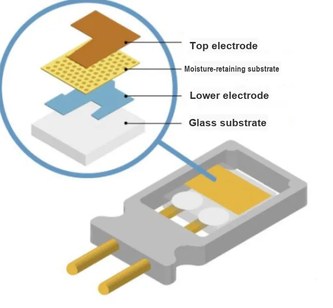
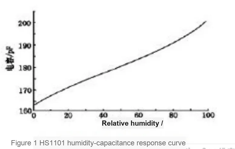
In the scenarios of drying base stations and product testing, HDS can also be used to record the complete change process of materials: water absorption, water squeezing and drying. The sensor outputs data such as capacitance value, channel count value, difference value and temperature via the UART interface and Modbus-RTU protocol, and the host computer can use Modbus Poll for real-time observation and log saving.Based on this, R&D personnel can analyze the impacts of materials, installation clearances, structural curvatures, ambient temperature and motor operation interference on the detection results, and establish calibration parameters and control thresholds that are more suitable for actual products, so as to improve the consistency and repeatability of dry-wet judgment.
I. Module Introduction
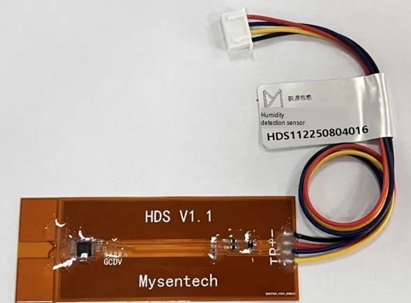
HDS is a humidity detection sensor developed by Minyuan Sensing for the cleaning industry, which adopts the 10-channel multi-mode wideband digital capacitive processor MCP1081S as the core, and integrates functions such as capacitive measurement, signal acquisition, microprocessor algorithm, temperature compensation and interface communication. The sensor features an FPC flexible structure, which can be adapted to the installation of cylindrical curved surfaces with different radians, and can penetrate non-metallic media such as plastic to complete non-contact dry and wet detection.
- It can quantify the changes in the dry and wet degree of different materials, and has high sensitivity to the change of water content;
- It adopts the differential capacitance detection principle and is equipped with an environment reference channel, delivering strong anti-interference performance.
- Built-in MCU processing function, supporting calibration, average times and channel parameter configuration;
- The chip integrates a temperature detection function, which can be used for temperature compensation;
- It features simple power supply and communication interfaces, making it suitable for embedding into devices for continuous detection.
II. Introduction to Major Chips
2.1 Chip Overview
The MCP1081S serves as the core of HDS's capacitance measurement and data processing. Its multi-channel broadband capacitance measurement capability, combined with dedicated sensing electrodes and software algorithms, can mitigate the impacts of factors such as plastic walls, air gaps, motor drive noise, and uneven humidity distribution. HDS externally provides register data including capacitance values, channel count values, frequency, temperature, difference values, and version information, facilitating trend analysis and classification judgment for the host computer or main controller.
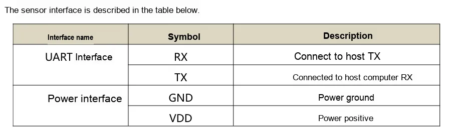
2.2 Pin Definition
2.3 Functional Block Diagram
The signal chain of HDS can be summarized as follows: the FPC differential sensing electrodes and the environmental reference channel sense changes in dielectric properties, the MCP1081S completes multi-channel capacitance sampling and frequency measurement, the on-chip MCU performs calibration, averaging, difference calculation and temperature compensation, and finally outputs continuous data to the main controller via UART/Modbus-RTU. The current product manual does not provide an independent functional block diagram with graphical representation, and this section is organized based on the functions described in the manual.
2.4 Performance Parameters
Project | Specifications |
Typical Accuracy | Five-level detection is carried out for typical water absorption states of cleaning consumables such as roller brushes and mop cloths. |
detection resolution | A 1% change in humidity can cause a continuous change in capacitance |
Sensing Distance | 0mm~5mm Non-metallic Medium |
Communication Interface | UART, Modbus protocol data output |
Supply Voltage | 2V~5V |
Peak Operating Power Consumption | 4.12mA@5V |
Operating Temperature Range | -40℃~+85℃ |
Product Dimensions | 80mm × 30mm × 1mm (L × W × H) |
2.5 Reference Circuit
The basic wiring consists of four wires: VDD, GND, TX and RX: VDD is connected to a 2V~5V power supply, GND is for common grounding, the TX of HDS is connected to the RX of the main controller, and the RX of HDS is connected to the TX of the main controller. In actual product design, interface compatibility verification shall be completed in combination with the IO level of the main controller, cable length and power supply noise; the complete electrical design shall be subject to the hardware documents subsequently provided by Minsensor.
2.6 Chip Configuration
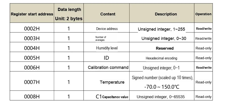
HDS can configure the device address, averaging times, calibration commands and calibration parameters of two channels via Modbus registers. The factory default address of the device is 0x01; the range of averaging times is 0 to 30. Before writing the configuration, you should read and retain the original value first, and re-read for confirmation after writing. The calibration operation shall be carried out after the installation position is fixed, the state of the measured material is clear and the environment is stable, so as to avoid mistaking structural assembly changes as the humidity baseline.
2.7 Communication Interfaces and Related Protocols
Communication is implemented with Modbus-RTU carried over UART. The basic parameters are 9600bps, 8 data bits, no parity, 1 stop bit (8N1), and CRC-16/MODBUS is adopted for error check. The device address must be unique within the same communication network, with the factory default being 0x01. It supports function codes 0x03 for reading holding registers and 0x06 for writing a single register; for 16-bit register data, the high byte comes first, while for CRC, the low byte comes first followed by the high byte.
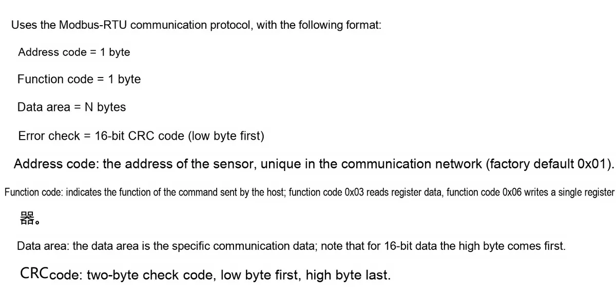
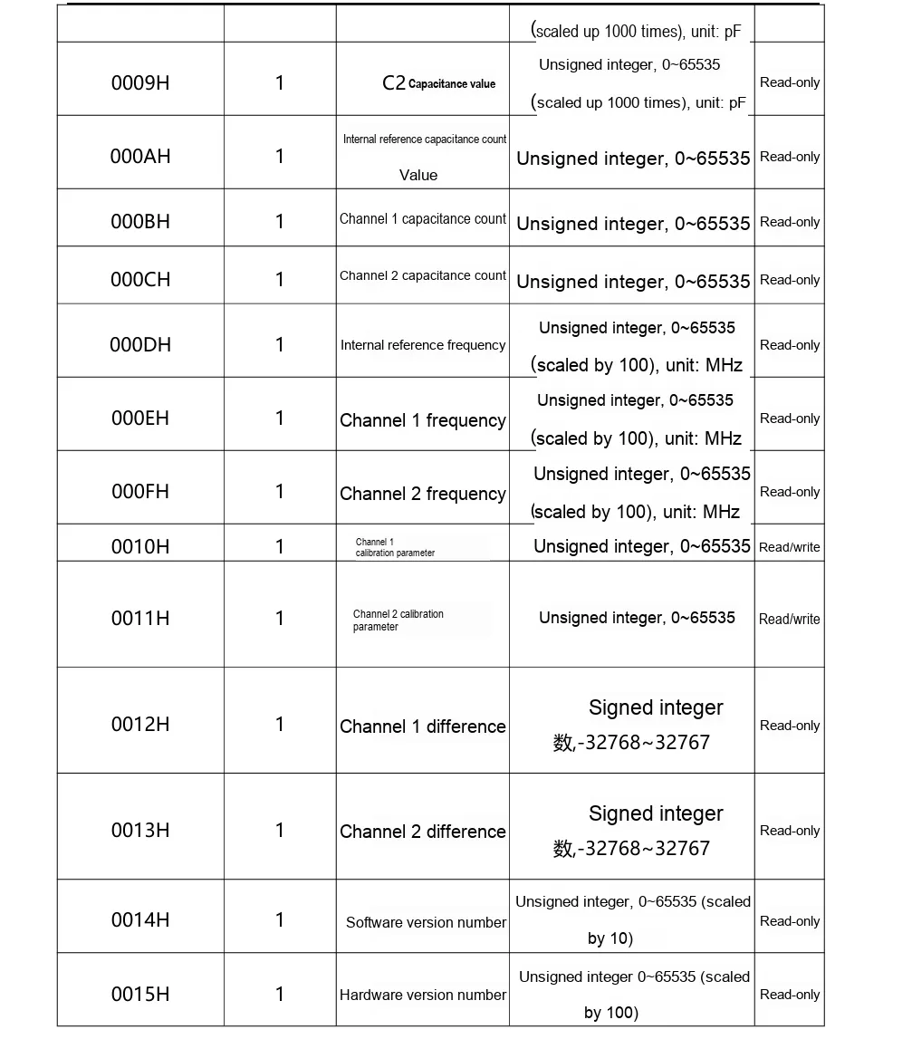
Temperature reading example: To query 1 register starting at address 0x0007 from device address 0x01, the request frame is 01 03 00 07 00 01 35 CB. The temperature register stores a signed value amplified by a factor of 10; for instance, a raw value of 287 corresponds to 28.7°C.
Capacitance Reading Example: To query 2 registers starting at address 0x0008, the request frame is 01 03 00 08 00 02 45 C9. Both C1 and C2 capacitance values are scaled up by a factor of 1000; for instance, a raw value of 7704 corresponds to 7.704 pF.
2.8 Register Definition
III. Circuit Engineering
3.1 Circuit Source Engineering
To obtain the source project of the circuit, please refer to the link below:
https://mysentech.com/productinfo/5921748.html
3.2 Module Usage Instructions
3.2.1 Installation, Wiring and Initial Inspection
- Place the FPC sensing area closely against the test position or fix it with a non-metallic medium of 0mm to 5mm in between, and avoid metal shielding, loosening and air gap changes;
- Wire the connections as VDD, GND, TX, RX, ensure the main controller and HDS share a common ground, and cross-connect their transmit and receive lines;
- Powered by a 2V to 5V supply, it first reads the device address, software version, hardware version and temperature after power-on to confirm that the communication and data scaling are correct;
- Perform calibration under a specified dry reference condition, then use representative humidity samples to verify the variation trend and repeatability of C1, C2, count value and difference value as a function of moisture content state;
- Baselines and gear thresholds shall be established separately for different materials, thicknesses and installation curvatures, so as to avoid directly applying the parameters of other structures.
3.2.2 Usage of Modbus Poll
Modbus Poll is a universal Modbus master debugging tool compatible with all capacitive sensors in this series that support the Modbus-RTU protocol. It enables quick serial communication debugging, real-time data reading and log export between sensors and computers, serving as a universal host computer tool for verifying sensor functions and collecting test data. The software supports Modbus RTU/ASCII/TCP/IP protocols, is compatible with multiple register types and data formats, and its operation process is universal for the entire series of sensors.
Before use, you need to complete the software installation and activation first. You can download the installation package through official channels; the first launch supports a 30-day trial, and you can also enter a registration code for permanent activation. After the hardware connects the sensor to the computer, open the software and click "Connection" - "Connect", then configure the serial port parameters (Port Number, baud rate, data bit/parity bit/stop bit; this series of sensors defaults to the 9600 Baud, 8N1 format, subject to the specification sheet of the corresponding specific model) in the pop-up window, and confirm to establish a communication connection.
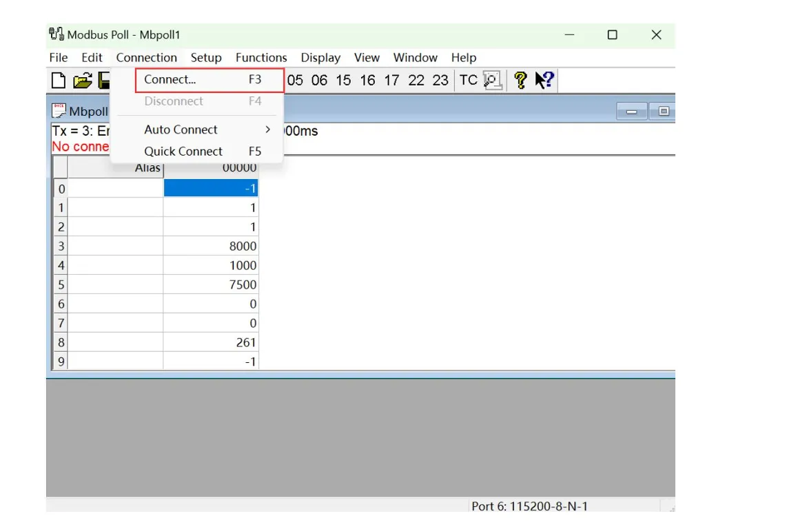
After connecting to a computer via a USB-to-UART module, select "Connection" - "Connect" in Modbus Poll, choose the corresponding serial port, and configure it to 9600 Baud, 8 Data Bits, None Parity, 1 Stop Bit, RTU. Once the connection is established, real-time data can be read according to the register table.
To save test data, select "Setup" - "Excel Log" in sequence. Select "Each read" to record every update; select "Select" and set the "Rate" to 1s to record once per second. In the manual example, set "Stop after" to 1048570 entries, confirm and click "OK" to start recording.
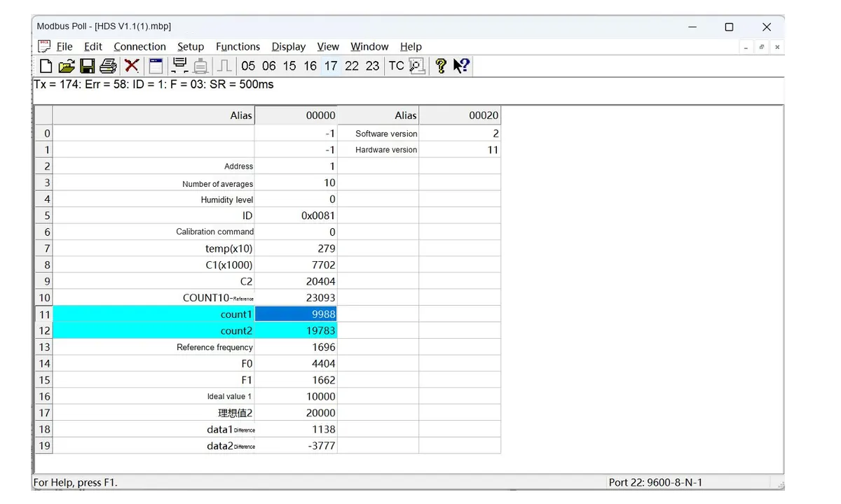
The following is a description of the general operation process:
- Serial Port Connection Configuration: After connecting the sensor to the computer via a USB-to-serial port module, launch the Modbus Poll software, click "Connection" - "Connect" on the menu bar, select the COM Port Number corresponding to the sensor in the pop-up window, and configure the serial port parameters matching the sensor (baud rate, data bits, parity check mode, stop bits; this series of sensors defaults to 9600 Baud, 8N1 format), then confirm to establish a communication connection.
- Import Sensor Configuration File: The software supports importing
. mbppre-configuration files corresponding to various sensor models. These files come with preset register addresses, data formats, and alias definitions, eliminating the need for manual register configuration. Simply open the. mbpfile for the corresponding sensor in the software to automatically load all parameters. Once the connection is established, real-time detection data of the sensor (such as dust/rain/frost thickness values, status flag bits, etc.) will be displayed directly. - Data Logging (Optional): If you need to save test data, you can configure logging rules via the "Setup" - "Excel Log" function. It supports logging data at fixed intervals or with every data update, and allows you to set a maximum number of log entries, facilitating subsequent analysis and verification of sensor data.
The above are the general basic operations of the host computer. For the. mbp preconfiguration files, specific register definitions and special configuration details of different sensor models, please refer to the content in "VII. Related Materials".
3.3 Application Experiment
It is recommended to conduct a five-range humidity calibration experiment with the target cleaning consumables and actual assembly structure: first record the counts, difference values and temperatures of C1, C2 and the two channels in a completely dry state, then humidify step by step according to the preset moisture content gradient and sample after stabilization; perform multiple dry-wet cycles for each range, and calculate the mean value, fluctuation and range interval. Subsequently, introduce operating conditions such as motor operation, structural vibration, different ambient temperatures, and 0mm~5mm non-metal isolation layers to verify the anti-interference capability and temperature compensation effect of the algorithm. The mass production threshold shall be based on the target material, assembly tolerance and actual working condition data.
Here, we use the GraftPort-RP2040 development board for testing, and the HDS humidity detection sensor communicates with the main controller via the UART interface
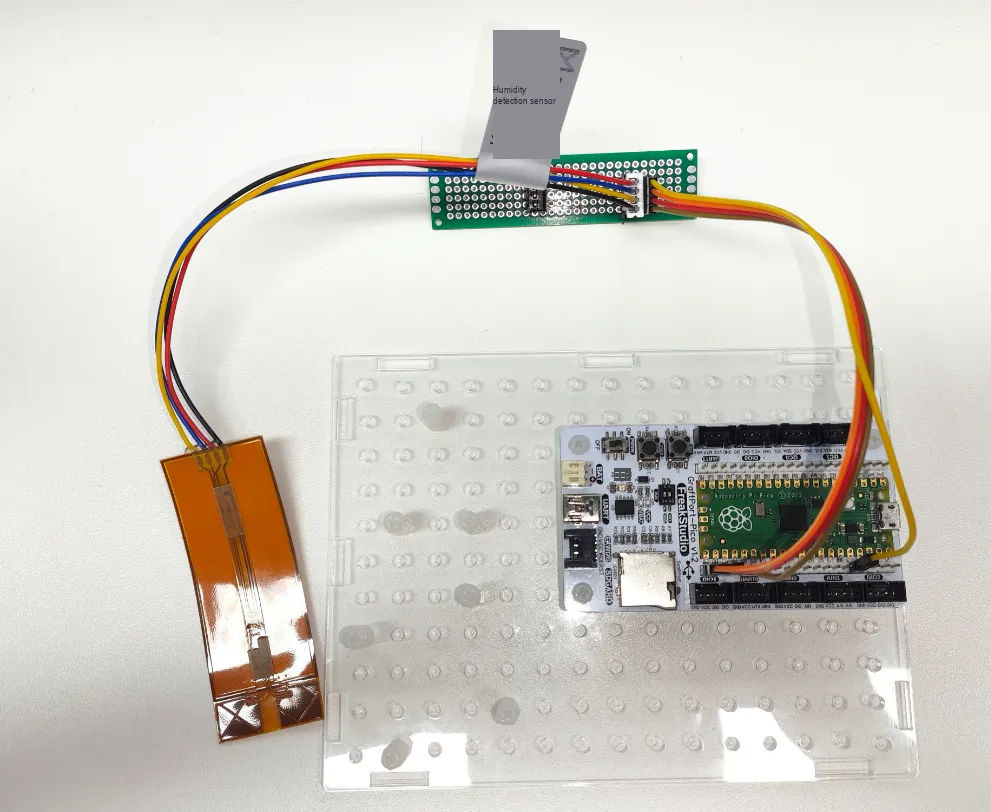
This diagram illustrates the HDS temperature and humidity detection module and the GraftPort-RP2040 development board's UART wiring method.
The module connections are shown in the following table:
Development Board Pins | Module Pins | Description |
Pin 16 |
|
|
Pin 17 |
|
|
Here, we need to search for the relevant driver packages on uPyPI: https://upypi.net/zh/

This diagram demonstrates the process of searching for the WS61 driver package in uPyPI.
Enter hds_driver to search, and the following will be displayed:

This figure shows hds_driver search results, which are used to confirm the corresponding driver package.
Click to copy the local installation command:
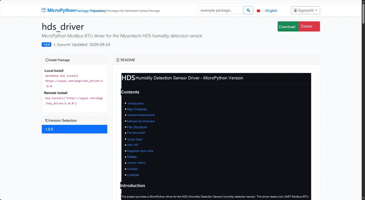
This diagram shows the interface for copying the HDS driver installation command, which facilitates the completion of environment preparation.
Import the module driver library code via the mip tool. Below are the usage commands for the mpremote tool:
mpremote mip install https://upypi.net/pkgs/hds_driver/1.0.0After importing, copy the following main.py code into our project:
# Python env   : MicroPython v1.23.0
# -*- coding: utf-8 -*-
# @Time    : 2026/08/21 16:00
# @Author  : December
# @File    : main.py
# @Description : Example of data acquisition from the Minyuan HDS humidity detection sensor
# @License : MIT

# ======================================== Import Modules =========================================

import time
from machine import Pin
from umodbus.serial import Serial as ModbusRTUMaster
from hds import HDS

# ======================================== Global Variables ============================================

PRINT_INTERVAL_MS = 1000

# ======================================== Functions ============================================

# ======================================== Custom Classes ============================================

# ======================================== Initialization ==========================================

time.sleep(3)
print("FreakStudio: HDS Humidity Detection Sensor Initialization")

# RP2040 UART0: GP16 is TX, GP17 is RX.
modbus = ModbusRTUMaster(
    uart_id=0,
    baudrate=9600,
    data_bits=8,
    stop_bits=1,
    parity=None,
    pins=(Pin(16), Pin(17)),
)

# The HDS default Modbus address is 0x01; retry twice on failure.
sensor = HDS(
    host=modbus,
    address=0x01,
    retries=2,
    retry_delay_ms=50,
)

# ========================================  Main Program  ============================================

last_print_time = time.ticks_ms() - PRINT_INTERVAL_MS

try:
    print("Device: %s" % sensor.read_device_info())
    while True:
        current_time = time.ticks_ms()
        if time.ticks_diff(current_time, last_print_time) >= PRINT_INTERVAL_MS:
            data = sensor.read_basic_measurements()
            print(
                "T={:.1f} C, C1={:.3f} pF, C2={:.3f} pF".format(
                    data["temperature_c"],
                    data["c1_pf"],
                    data["c2_pf"],
                )
            )
            last_print_time = current_time
        time.sleep_ms(10)
except KeyboardInterrupt:
    print("Program interrupted by user")
except OSError as error:
    print("Hardware communication error: %s" % str(error))
except Exception as error:
    print("Unknown error: %s" % str(error))
finally:
    print("Cleaning up resources...")
    sensor.deinit()
    if hasattr(modbus, "_uart") and hasattr(modbus._uart, "deinit"):
        modbus._uart.deinit()
    del sensor
    del modbus
    print("Program exited")
Burn the code, open the terminal, and the output is as follows:
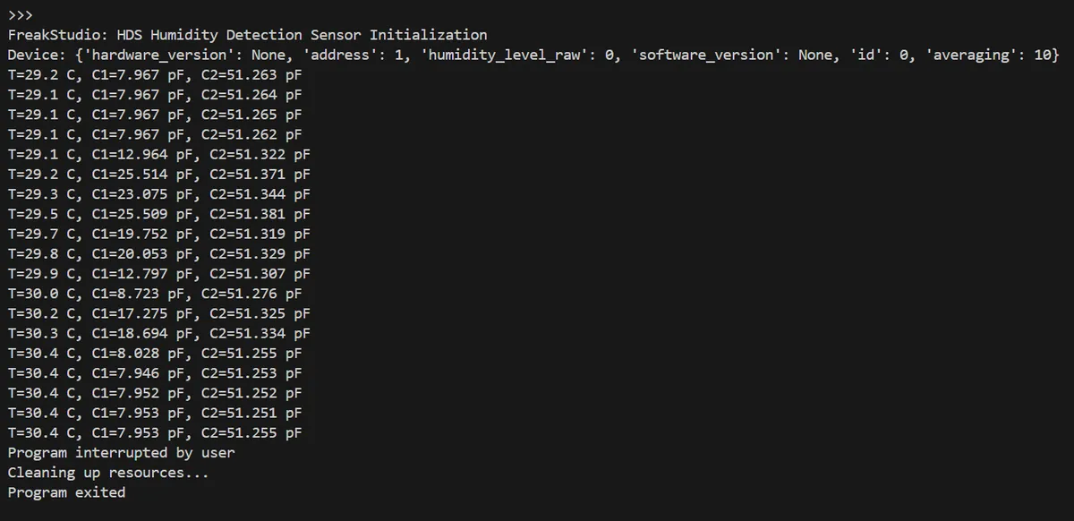
This diagram shows the output section of the HDS sample program, which contains status information of capacitance, humidity and pressure capacitance
4. Drivers
5. BOM & Recommended Alternative Parts
Materials | Intended Use or Requirements | Replacement Instructions |
HDS Humidity Detection Sensor | Capacitive non-contact moisture detection, 2V~5V, UART/Modbus-RTU | No direct replacement model is provided |
4-wire connection cable / matching connector | VDD, GND, TX, RX | Select connectors and wiring sequences according to the device side to ensure reliable contact |
USB to UART Module | Computer Debugging and Modbus Poll Data Acquisition | Must be compatible with system IO level |
Non-metallic fixing structure | Keep the relative position between the sensor and the measured material stable | The material and thickness shall be included in the calibration, and the sensing distance shall not exceed 5mm. |
VI. Revision History
Document Version | Date of Revision | Modifier | Modify Content |
v1.0 | 2026-08-21 | Mi Ming Xuan | Initialize the document |
VII. Relevant Materials
HDS Humidity Detection Sensor Product Manual-Minyuan 202508.pdf 802 KB